Publicité
Les langues disponibles
Les langues disponibles
Liens rapides
Rel. 1.6
All manuals and user guides at all-guides.com
Manuel d'instructions
Bedienungsanweisung
Instrucc iones para el uso
Manuale d'istruzioni
Instruc tion manual
230 V~ ±10%
50/60Hz
3x220 V~
2200W max
25÷50Hz
I
EN
F
DE
E
Publicité

Manuels Connexes pour EBARA Press-o-Matic


Sommaire des Matières pour EBARA Press-o-Matic
- Page 1 All manuals and user guides at all-guides.com 230 V~ ±10% 50/60Hz 3x220 V~ 2200W max 25÷50Hz Manuale d’istruzioni Instruc tion manual Manuel d’instructions Bedienungsanweisung Instrucc iones para el uso Rel. 1.6...
- Page 2 All manuals and user guides at all-guides.com...
- Page 3 All manuals and user guides at all-guides.com ATTENZIONE: LEGGERE ATTEN TAMEN TE QUESTO MANU ALE ISTRUZIONI PR IM A DELL’INSTALLAZ IONE O MESSA IN FUNZIONE. L’install azione (collegamenti elettrici ed idraulici) e la manu tenzione del presente apparecchio deve essere eseguita da personale qualificato ed in possesso dei requisiti tecnici indicati dalle norme di sicurezza del paese di installazione del prodotto nonché...
- Page 4 All manuals and user guides at all-guides.com INDICE INGOMBRI - DIMENSIONI - IDENTIFICAZIONE…………………..…………………..5 DESCRIZIONE……………………………………………………………………………...…6 DATI TECNICI………………………………………………………………………………...6 FUNZIONALITA’…………………………………………………………………………..6 PROTEZIONI……………………………………………………………………………...…...7 INSTALLAZI ONE COLLEG AMENTO IDR AULICO……………………………………………………….7 COLLEG AMENTO ELETTRICO……………………………………………………..8 MESSA IN FUNZIONE………………………………………………………..………...12 PROG RAMMAZIONE DESCRIZIONE INT ERFACCI A…………………………………………………………12 DESCRIZIONE TASTI……………………………………………………………………12 STRUTTURA DE I MENU’………………………………………………………………..13 DESCRIZIONE DEI P AR AMETRI E DEL LE SCHERMATE…….………………….13 ALLARMI…..………………………………………………………………………………16 ANOMALIE POSSIBILI……………………………………………………………………...17...
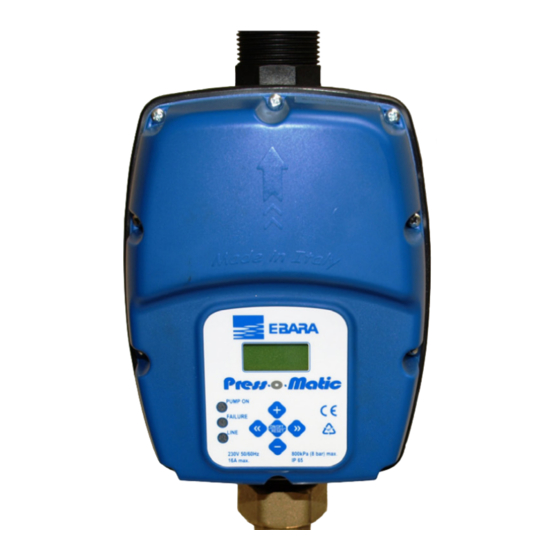
- Page 5 All manuals and user guides at all-guides.com ↔ INGOMBRI - DIMENSIONI - IDENTIFICAZIONE Press•o•Matic...
- Page 6 All manuals and user guides at all-guides.com DESCRIZIONE Press•o•Matic è un dispositi vo elettronico che controlla l’avvio e l’arresto di un a elettropompa, basato su tecnologia ad inverter. Grazie a questa tecnologia esso è in grado di modulare la frequenza (Hz) della corrente che arriva al motore in modo da farne variare il regime di rotazione giri/minuto a seconda dell a richiesta di acqua dall’impianto.
- Page 7 All manuals and user guides at all-guides.com PR OTEZIONI √ Marcia a secco √ Sotto-tensione di alimentazione (intervento a circa 200 Volt) √ Sovra-tensione di al imentazione (intervento a circa 260 Volt) √ Corto circuito sui terminali di uscita √ Controllo amperometrico su uscita motore √...
- Page 8 All manuals and user guides at all-guides.com COLLEGAMENTO ELETTRICO: Inserire i cavi elettrici negli apposi ti pressacavi rispettando il corretto ordine di montaggio di tutt i i componenti. Fis sare sufficientemente i dadi filettati in modo da evitare la trazione e la rotazione dei cavi dall’esterno. Il pressacavo per il contatto ausi liario è...
- Page 9 All manuals and user guides at all-guides.com COLLEG AMENTO DI LINE A TERRA L’alimentazione del dispositivo è di tipo monofase a 230 Volt 50/60Hz. L’impianto elettrico al quale l’apparecchio viene collegato deve essere conforme alle normative vigenti di sicurezza e deve quindi essere dotato di: - interruttore magnetotermico automatico ad elevato potere d’interruzione con corrente d’intervento proporzionata alla potenza della pompa in stallata ( vedi tabella seguente)
- Page 10 All manuals and user guides at all-guides.com Attenersi inoltre alle lim itazioni di install azione dichiarate dal costruttore dell’elettropompa alla quale Press•o•Matic viene collegato. ATT ENZIONE: - tutti i col legamenti elettri ci devono essere eseguiti da personale speciali zzato - un col legamento non corretto del motore elettrico può...
- Page 11 All manuals and user guides at all-guides.com manuale alle sezione “GRUPPI DI PRESSURIZZ AZIONE”. IMPOSTAZIONE P ARAMETRO “CONTATTO AUSILI ARIO” = “2” - Funzione di avvio ed arresto a distanza Con il par ametro “CON TATTO AUSILIAR IO” impostato su “2”, Press•o•Matic è predisposto per essere avvi ato ed arrestato a dist anza in funzione delle richieste dell’impianto.
- Page 12 All manuals and user guides at all-guides.com MESSA IN FUNZIONE: ATT ENZIONE: al la pri ma accensi one evitare di far funzi onare il dispositi vo per molto tempo senza acqua per evitare surriscal damenti dell’i nverter! Riempire il tubo di aspirazi one dell a pompa prima di alimentare il si stema.
- Page 13 All manuals and user guides at all-guides.com STRUTTURA DEI MENU’ DESCRIZIONE DEI PAR AMETRI E DELLE SCHERMAT E PARAMETRI UTENTE: Questi parametri sono normalmente accessibili quando il dispositivo è alimentato. Schermata principale: quando Press•o•Matic funzion ando regolarmente, nella prima linea del display vene visu alizzat a la pressione istantanea rile vata dal sistema;...
- Page 14 All manuals and user guides at all-guides.com Pmax2: questa pagina appare solo se il parametro “CON TATTO AUSILIAR IO” è impostato sul valore “3” ( funzione di doppio set-point); tramite questo par ametro è possibile impostare il valore di set-point secondario del dispositivo.
- Page 15 All manuals and user guides at all-guides.com Lingua: è possibile personalizzare l a lingua dei menù e dei messaggi di allarme. Agire sui tasti + e – per modificare il valore del parametro. PARAMETRI IN STALL ATORE: Questi parametri sono contenuti in schermate nascoste e, solitamente, dovrebbero essere modificati solo in fase di installazione.
- Page 16 All manuals and user guides at all-guides.com intervento più lunghi mentre un sovr accarico intenso rende l’interruzione molto più rapida. Il p arametro è impostabile da 0,5 a 9,7 A. All’accensione del dispositivo, se il p arametro Imax è impostato a 0,5 A (impostazione di fabbrica), sul display appare autom aticamente la pagin a di i mpost azione della corrente massim a e nessuna azione è...
- Page 17 All manuals and user guides at all-guides.com Sovraccarico: questo allarme appare quando l’assorbimento dell’elettropompa ha superato il valore di corrente massima impost ato nel valore Imax; questo può accadere in seguito a condizioni di funzion amento estremamente gravose dell’elettropompa, a continue ripartenze ad intervalli d i tempo molto ravvicin ati, a problemi negli avvolg imenti del motore od in seguito a problemi di collegamento elettrico tra il motore stesso ed il Press•o•Matic.
- Page 18 All manuals and user guides at all-guides.com La pompa no n si arresta L’impianto ha perdite consistenti oppure la val vol a di ritegno dell’apparecchio si è bloccata a cau sa dello sporco; provare a muo vere la val vol a di ritegno con le dit a e verificare che la molla sia in gr ado di garantirne la chiusura.
- Page 19 All manuals and user guides at all-guides.com Data installazione …./…./……. Instal latore Cliente Marca-modello pompa N° seri ale Press•o•Matic VALORI IMPOSTATI ALL’INSTALLAZI ONE Pmax ……………...bar Pmax2 ……………...bar Pmi n ……………...bar Ritardo stop ……………...secondi Tempo auto-reset ……………...minuti Test auto-reset ……………...N° test Partenze/ora max ...
- Page 20 All manuals and user guides at all-guides.com WARNING: READ THIS HANDBOOK CAREFULL Y BEFORE INSTALLING OR STAR TING THE DEVICE. Installation (electrical and hydraulic connections) and mainten ance of this device must be performed by qualified personnel who satisfy the technical requirements indicated by the safety standards in force in the country of installat ion and who are capab le of fully understanding the contents of this instruction manual.
- Page 21 All manuals and user guides at all-guides.com C ONTENTS OVER AL L SIZ E - DIMENSIONS - IDENTIFIC ATION………………..………………….22 DESCRIPTION……………………………………………………………………………...…23 SPECIFICAT IONS …………………………………………………………………………..23 FEATURE S……………..…………………………………………………………………..23 DEVICE PROT ECTION FEATURES …………..……………………………………...…...24 INSTALL ATION HYDRAUL IC CONNECTION ……………………..……………………………………..24 ELECTRIC AL CONNECTION …………………………………………………………...25 ST ART-UP…………………………………………………………..……………………….29 PROG RAMMING DESCRIPTION OF THE INTERF ACE…………………………………………………...29...
- Page 22 All manuals and user guides at all-guides.com ↔ OVERALL SIZE - DIMENSIONS -IDENTIF ICATION Press•o•Matic...
- Page 23 All manuals and user guides at all-guides.com DESCRIPTION Press•o•Matic is an electronic device, employing in verter-based technology, which controls motor pump stopping and starting functions. Thanks to the particular type of technology used, it can modulate the frequency (Hz) of the motor’s input current to alter the speed (rpm) according to the water delivery rate required from the system.
- Page 24 All manuals and user guides at all-guides.com DEVICE PROTEC TION FEATURES √ Dry running √ Undervoltage on power line (activation at approx. 200 Volt) √ Overvoltage on po wer line (activation at approx. 260 Volt) √ Output terminal short circuit √...
- Page 25 All manuals and user guides at all-guides.com ELECTRIC AL CONNECTI ON: Fit the electric wires into the relative wire clamps, making sure the correct assembly order is maintained for all the components. Secure the threaded nuts tightly enough to prevent the wires being pulled or turned from the outside.
- Page 26 All manuals and user guides at all-guides.com LINE CONNECTION EARTH The device has a single-phase 230 Volt 50/60Hz power line. The electrical system to which the equipment is connected must comply with the safety regulations in force and must therefore be equipped with: - an autom atic magnetothermal s witch with high breaking capacity and with a trigger current proportional to the capacity of the pump installed (see chart below)
- Page 27 All manuals and user guides at all-guides.com WARNING: - all wi ring up must be carried out by specially trained personnel - an incorrect motor pump connection could result i n damage to the device or the pump motor. - the manufacturer cannot be held responsibl e for any ki nd of damage to peopl e and/or thi ngs ensuing from failure to compl y with the contents of this paragraph.
- Page 28 All manuals and user guides at all-guides.com SETT ING OF “AUXILIAR Y CONTACT” P ARAMET ER = “2” – Remote on/off control function When the “AUXILIAR Y CON TACT” p arameter is set on “2” the Press•o•Matic is set to be switched on and off by remote control according to the system EXTERNAL requirements.
- Page 29 All manuals and user guides at all-guides.com START-UP: WARNING : do not all ow the pump to run for l ong without water the first time it i s switched on otherwise the inverter will overheat! Prime the pump before switching on the system. Once all the electrical connections have been made and checked to ensure they are correct, close the unit’s co ver and switch on the power.
- Page 30 All manuals and user guides at all-guides.com MENU STRUCTURE DESCRIPTION OF THE PAR AMETER S AND SCREEN PAG ES USER PAR AMETERS: These parameters are accessible when the device is on. Main screen page: when the Press•o•Matic is in the st and ard operation mode, the first line on the display shows the instant pressure reading;...
- Page 31 All manuals and user guides at all-guides.com Pmax2: this page is only disp layed if the “AUXIL IAR Y CON TACT ” parameter is set on “3” (second set-point function); this parameter is used to set the secondary set-point of the de vice. When the auxiliary contact is externally closed the Pmax2 pressure value becomes the new set-point according to which the Press•o•Matic adjusts the speed of the motor pump.
- Page 32 All manuals and user guides at all-guides.com Language: The language used for the menus and the alarm mess ages can be selected by the user. Use the + and – buttons to alter the parameter setting. INSTALLER P ARAME TERS: These parameters can be found on hidden pages and usually they should only be changed in the instal lat ion phase.
- Page 33 All manuals and user guides at all-guides.com set the maximum current value wil l be displayed; no action can be carried out until the maximu m absorption value has been set. Auxili ary contact: use this parameter to select the function to be associated with the auxili ary contact;...
- Page 34 All manuals and user guides at all-guides.com Overload: This alarm appears when the absorption of the motor pump is greater than the maximum current value set (Imax); th is may be caused by extremely difficult working conditions for the motor pump, problems related to the motor winding , if the pump is restarted continuously at short intervals or following problems with the wiring of the motor to the Press•o•Matic.
- Page 35 All manuals and user guides at all-guides.com The pump is runni ng at top speed but performance l evels are low The pump might be running backwards. Try in verting the rotation direction. The pump is d amaged or there is foreign matter clogging the waterway. When more water is required of the system, the pressure drops This is a normal condition which is due to the fact that the device is unable to force the pump above its capacity curve.
- Page 36 All manuals and user guides at all-guides.com Installation date …./…./……. Fitter Customer Pump make/model Press•o•Matic serial n. VALUES SE T AT INST ALLATION Pmax ………………bar Pmax2 ………………bar Pmi n ……………..bar Stop delay ………………seconds Auto-reset ti me ………………mi nutes Auto-reset test Test n.
- Page 37 All manuals and user guides at all-guides.com ATTENTION: LIRE ATTEN TIVEMEN T CE M ANUEL AVANT L ’INSTALLATION OU LA MISE EN SER VICE. L’installation (raccordements électriques et hydrauliques) et la maintenance de cet appareil doivent être effectuées par du personnel qualifié, possédant l'expertise technique prescrite par les normes de sécurité du pays d'installation du produit et en mesure de comprendre pleinement les indications de ce manuel d’instructions.
- Page 38 All manuals and user guides at all-guides.com TABLE DES MATIÈRES ENCOMB REMENTS - DIMENSIONS - IDENTIFICATION……………………..……….39 DESCRIPTION……………………………………………………………………………..40 DONNÉES TECHNIQU ES……………………………………………………………...…..40 FONCTIONNALIT ÉS……………………………………………………………………..40 PROTECTIONS…………………………………………………………………………..….41 INSTALL ATION BRANCHEMENT HYDRAU LIQUE………………………………………………………41 BRANCHEMENT ÉLECTRIQUE………………………………………………………..42 MISE EN SER VICE……………………………………………………………………...….46 PROG RAMMATION DESCRIPTION DE L’INTERF ACE…………………………...……….………………….46 DESCRIPTION DES TOUCHES…………………………………………………………..46 STRUCTURE DES MENUS………………………………………………………………...47 DESCRIPTION DES P ARAMÈTRES ET DES ÉCRANS……………………………….47...
- Page 39 All manuals and user guides at all-guides.com ↔ ENCOMBREMENTS - DIMENSIONS -IDENTIFICATION Press•o•Matic...
- Page 40 All manuals and user guides at all-guides.com DESCRIPTION Press•o•Matic est un dispositif électronique qui contrôle le démarrage et l’arrêt d’une électropompe, basé sur la technologie à convertisseur. Grâce à cette particularité, il est capable de moduler la fréquence (Hz) du courant qui arrive au moteur afin d’en modifier le régime de rotation en tours/minute selon la demande d’eau de l’installation.
- Page 41 All manuals and user guides at all-guides.com PR OTECTIONS √ Marche à sec √ Baisse de tension d’alimentation (intervention à environ 200 Volts) √ Surtension d’alimentation (inter vention à en viron 260 Volts) √ Court circuit sur les bornes de sortie √...
- Page 42 All manuals and user guides at all-guides.com BRANCHEMENT ÉLECTRIQUE : Introduire les câbles électriques dans les presse-étoupes appropriés en respectant l’ordre correct de montage de tous les composants. Fixer suffisamment les écrous filetés afin d’éviter la traction et la rotation des câbles à l’extérieur. Le serre- câble pour le contact auxiliaire est borgne : si l'on souhaite insérer un câble pour la commande à...
- Page 43 All manuals and user guides at all-guides.com BRANCHEMENT DE LIG NE TERRE L’alimentat ion du dispositif est du type monophasée à 230 Volts 50/60 Hz. L’inst all ation électrique à laquelle est branchée l’appareil doit être conforme aux normes de sécurité en vigueurs et doit donc être dotée de : - interrupteur magnétothermique automatique à...
- Page 44 All manuals and user guides at all-guides.com ATT ENTION : - tous l es branchements électriques doivent être réali sés par du personnel spécialisé - un branchement incorrect du moteur électrique peut entraî ner l’endommagement du di spositif et du moteur même de l a pompe. - le non-respect des prescri pti ons fournies dans ce paragraphe peut entraîner de graves dommages aux biens et/ou personnes, pour l esquels la société...
- Page 45 All manuals and user guides at all-guides.com CONFIGURATION PARAMÈTRE “CON TACT AUXILI AIRE” = “2” - Foncti on de démarrage et arrêt à distance Avec le paramètre “CONTACT AUXIL IAIRE ” configuré sur “2”, Press•o•Matic est prédisposé pour être mis en marche et arrêté à distance en fonction des CONTACT exigences de l'installation.
- Page 46 All manuals and user guides at all-guides.com MISE EN SERVICE : ATTENTION : l ors de la première mi se en service, évi ter de faire fonctionner l e dispositif sans eau de manière prolongée pour éviter l es surchauffes du convertisseur ! Remplir l e tuyau d’aspirati on de la pompe avant d’alimenter le système.
- Page 47 All manuals and user guides at all-guides.com STRUCTURE DES MENUS DESCRIPTION DES PARAMÈTRES ET DES ÉCRANS PARAMÈTR ES UTI LISATEUR : Ces paramètres sont normalement accessibles quand le dispositif est alimenté. Écran principal : lorsque Press•o•Matic fonctionne normalement, la première ligne de l’écran affiche la pression instantanée relevée par le système ;...
- Page 48 All manuals and user guides at all-guides.com Pmax2 : cette page n'app araît que si le par amètre “CON TAC T AUXIL IAIRE ” est configuré sur la valeur “3” (fonction de double set- point) ; grâce à ce paramètre, il est possible de définir la valeur de set-point secondaire du dispositif.
- Page 49 All manuals and user guides at all-guides.com fréquentes ou non justifiées, il est conseillé d’augmenter le paramètre de cette page en appuyant sur la touche « + » . Tandis que si l’on désire désactiver complètement le contrôle des pertes, appuyer sur la touche «...
- Page 50 All manuals and user guides at all-guides.com d'intervention plus long, tand is que une surcharge intense rend l'interruption beaucoup plus rapide. Le paramètre est configurable entre 0,5 et 9,7 A. Lors de la mise en marche du dispositif, si le paramètre Imax est configuré...
- Page 51 All manuals and user guides at all-guides.com convertisseur en présence d’un court-circuit à la sortie peut sérieusement endommager l'appareil et être une source de danger pour l'utilisateur. Surcharge : cette alarme apparaît quand l'absorption de l'électropompe a dépassé la valeur de courant maxim al configurée dans la valeur Imax ; cela peut se produire à...
- Page 52 All manuals and user guides at all-guides.com La pompe ne s’arrête pas L’installation a des fuites importantes ou la soupape de retenue de l’appareil s’est bloquée à cause de la saleté ; essayer de déplacer la soupape de retenue avec les doigts et vérifier que le ressort soit capable d’en garantir l a fermeture.
- Page 53 All manuals and user guides at all-guides.com ATT ENTION : le di spositif ne contient aucun composant pouvant être réparé ou remplacé par l’util isateur final. Il est donc conseillé de ne pas retirer le couvercle de protection de la carte électronique afi n d’éviter l ’annul ation de la garantie ! Date d’installation …./…./…….
- Page 54 All manuals and user guides at all-guides.com ACHTUNG: VORL IEGENDE HANDBUCH INSTALL ATION UND/ODER INBE TR IEBNAHME GENAU LESEN. Die Installation (elektrische und hydraulische Anschlüsse) und Wartung des vorliegenden Geräts darf nur von qualifi ziertem Fachpersonal durchgeführt werden, das den geltenden Vorschriften zu technischen Anforderungen im Land, in dem das Produkt installiert wird, entspricht und in der L age ist, die Ausführungen in der vorliegenden Bedienungsanleitung vollst ändig zu verstehen.
- Page 55 All manuals and user guides at all-guides.com INHALTSVERZEIC HNIS PLATZBEDARF - DIMENSIONEN - IDENTIFIZIERUNG………………….……………56 B ESCHREIB UNG ………….………………………………………………………………..57 TECHNISCHE D AT EN…………………………………………………………………….….57 FUNKTIONEN …………….………………………………………………………………..57 SCHUTZ……………………..……………………………………………………………..….58 INSTALL ATION WASSER ANSCHLUSS…...………………………………………………………………..58 ELEKTRISCHER ANSCHLU SS……………………………………………………...…...59 INBETRIEB SETZUNG …………………………………………………………………….63 PROG RAMMIERUNG BESCHREIB UNG DER SCHNITTST ELLE……………………….……………………..63 BESCHREIB UNG DER TAST EN………………………………….…..………………….63 AUFBAU DER MENÜS ……………………………………………………………………64 BESCHREIB UNG DER PARAMETER UND...
- Page 56 All manuals and user guides at all-guides.com ↔ PLATZBEDARF - DIMENSIONEN - IDENTIFIZIERUNG Press•o•Matic...
- Page 57 All manuals and user guides at all-guides.com BESCHREIB UNG Press•o•Matic ist eine elektronische Vorrichtung, die das Ein- und Ausschalten einer Elektropumpe überwacht und auf Invertertechnologie beruht. Dank dieser Besonderheit ist Press•o•Matic imstande, die Frequenz (Hz) des am Motor ankommenden Stroms zu modulieren, so dass dieser seine Drehzahl/Minute je nach Wasseranfrage der Anlage variiert. Auf diese Weise ist der Druck zu den Abnehmern immer konstant und die Motoraufnahme ist immer proportional zur effektiven Anfrage der Anlage, mit einer bedeutenden Energieersparnis im Laufe der Zeit.
- Page 58 All manuals and user guides at all-guides.com SC HUTZ √ Trockenlauf √ Unterspannung der Versorgung (Auslösung bei ca. 200 Volt) √ Überspannung der Versorgung (Auslösung bei ca. 260 Volt) √ Kurzschluss an den Klemmen √ Stromsteuerung auf Motorausgang √ Übertemperatur im Inverter √...
- Page 59 All manuals and user guides at all-guides.com ELEKTRISCHER ANSCHLUSS: Die elektrischen Kabel in ihre Kabelhalter einführen und die korrekte Montagefolge aller Bestandteile beachten. Die Gewindemuttern ausreichend festziehen, damit die Kabel von außen nicht gezogen und gedreht werden können. Der Kabelhalter für die Hilfskontakt hat eine Kappe: wenn man ein Kabel für die Fernsteuerung einstecken will, muss die Plastikmutter mit einem Schraubenzieher durchbrochen werden, nachdem die Mutter von der Einheit entfernt wurde.
- Page 60 All manuals and user guides at all-guides.com Der Stromkabeltyp muss den An wendungsbedingungen entsprechen (Verwendung in trockenen oder nassen Haushaltsräumen, für die Installation in Innenräumen oder im Freien). LINIENANSCHLUSS ERDE Die Versorgung der Vorrichtung ist einphasig 230 V 50/60 Die elektrische Anlage, mit der das Gerät verbunden wird, muss konform mit den gültigen Sicherheitsvorschriften und daher mit folgendem ausgestattet sein:...
- Page 61 All manuals and user guides at all-guides.com Weiterhin sind die Installationsgrenzen, die der Hersteller der mit Press•o•Matic verbundenen Elektropumpe erklärt, einzuhalten. ACHTUNG : - alle el ektrischen Anschlussarbeiten müssen von Fachpersonal ausgeführt werden. - ein unkorrekter Anschluss des E-Motors kann di e Vorri chtung und den P umpenmotor sel bst beschädigen.
- Page 62 All manuals and user guides at all-guides.com EINSTE LLUNG PARAMETER “HILFSKONTAKT” = “2” - Ferngesteuerte Start- und Stoppfunktion Wenn der Parameter “HILFSKONTAKT” auf “2”, Press•o•Matic gestellt ist, ist er vorgerüstet, um je nach den Anforderungen der Anlage mit EXTERNER Fernsteuerung gestartet oder gestoppt zu werden. KONTAK T Diese Funktion ist nützlich, wenn der Start der Elektropumpe zusammen mit dem Start anderer Geräte...
- Page 63 All manuals and user guides at all-guides.com INBETRIEB SETZUNG: ACHTUNG: beim ersten Einschal ten sollte die Vorrichtung nicht langfristig ohne Wasser betri eben werden, um Überhitzungen im Inverter zu vermeiden. Das Ansaugrohr der Pumpe vor der Versorgung der Anl age mit Wasser füll en. Den Deckel der Einheit nach Durchführung aller elektrischer Anschlüsse und Kontrolle ihrer Korrektheit schließen und die Anlage mit Sp annung versorgen.
- Page 64 All manuals and user guides at all-guides.com AUFBAU DER MENÜS BESCHREIB UNG DER PARAMETER UND DER B ILDSCHIRMSEITEN B ENUTZER-PARAMETER: Diese Parameter sind normalerweise zugänglich, wenn die Vorrichtung versorgt wird. Hauptsei te: wenn Press•o•Matic ordnungsgemäß funktioniert, wird in der ersten Zeile des Displays der vom System gemessene Momentandruck gezeigt;...
- Page 65 All manuals and user guides at all-guides.com Pmax2: Diese Seite erscheint nur, wenn Parameter “HILFSKONTAKT” auf dem Wert “3” eingestellt ist (Funktion des doppelten Set-Point); durch diesen Parameter ist es möglich, den sekundären Set-Point-Wert der Vorrichtung einzustellen. Wenn der Hilfskontakt extern geschlossen wird, wird der im Pmax2 eingestellte Druckwert der neue Set-Point, mit dem Press•o•Matic die Drehzahlen der Elektropumpe reguliert.
- Page 66 All manuals and user guides at all-guides.com man dagegen die Kontrolle der Verluste vollst ändig deakti vieren möchte, wird die Taste “- “ gedrückt, bis “OFF” in der ersten unteren Zeile dieser Seite erscheint. Sprache: die Sprache der Menüs und Alarmmeldungen kann personalisiert werden.
- Page 67 All manuals and user guides at all-guides.com 0,5 bis 9,7 A eingestellt werden. Wenn der Parameter Imax bei Einschaltung der Vorrichtung auf 0,5 A gestellt ist (Werkseinstellung), erscheint auf dem Display automatisch die Einstellungsseite des Spitzenstroms, und es ist keine Aktion zulässig, wenn nicht vorher ein Aufnahmegrenzwert eingestellt wurde.
- Page 68 All manuals and user guides at all-guides.com Überlast: Dieser Alarm erscheint, wenn die Stromaufnahme der Elektropumpe den Spitzenstromwert überschritten hat, der im Wert Imax eingestellt ist; das k ann infolge von extrem schwierigen Betriebsbedingungen der Elektropumpe, bei fortlaufenden Neustartvorgängen mit sehr nahe liegenden Zeitintervallen, bei Problemen der Motoraufwicklung oder aufgrund von Problemen der Stromverbindung zwischen dem Motor und Press•o•Matic erfolgen.
- Page 69 All manuals and user guides at all-guides.com Di e Pumpe hält nicht an Anlage mit st arken Leckagen oder wenn das Rückschlagventil des Geräts durch Schmutz blockiert ist; versuchen, das Rückschlagventil mit den Fingern zu bewegen und prüfen, ob die Feder eine Schließung garantiert.
- Page 70 All manuals and user guides at all-guides.com ACHTUNG : di e Vorrichtung enthält keine El emente, die der Endbenutzer reparieren oder ersetzen kann. Daher den Schutzdeckel der elektronischen Steuerkarte nicht entfernen, da andernfall s die Garantie ungülti g wird! Installationsdatum …./…./…….
- Page 71 All manuals and user guides at all-guides.com ATENCIÓN: LEA DETENID AMEN TE ESTE M ANUAL DE INSTRUCCIONES AN TES DE LA IN STAL ACIÓN O PUESTA EN FUNCION AMIEN TO. La instalación (conexiones eléctricas e hidráulicas) y el mantenimiento de este aparato deben ser llevados a cabo por personal cualificado y que po sea los requisitos técnicos indicados en l as normas de seguridad del país de instalación del producto y que esté...
- Page 72 All manuals and user guides at all-guides.com ÍNDICE MEDIDAS MÁXIMAS – DIMENSIONE S – IDENTIFIC ACIÓN…………………..……..73 DESCRIPCIÓN……………………………………………………………………………...…74 DATOS TÉNICOS……………………………………………………………………………..74 CARACT ERÍSTIC AS……………….……………………………………………………..74 PROTECCIONES…………………………………………………………………………..75 INSTALACIÓN CONEXIÓN HIDRÁULIC A .…....…………………………………………………75 CONEXIÓN ELÉCTRIC A…….………………………………………....………..76 PUEST A EN FUNCIONAMIENTO…………………………………………....…..80 PROG RAMACIÓN DESCRIPCIÓN DE LA IN TERFAZ ………………………………………….…..…..80 DESCRIPCIÓN DE LAS TEC LAS……….…………………………………………..80 ESTRUCTURA DE LOS MENÚS…………………………………………………....81 DESCRIPCIÓN DE LOS P ARÁME TROS Y DE L AS VENT ANA .……...……….81...
- Page 73 All manuals and user guides at all-guides.com ↔ MEDIDAS MÁXIMAS – DIMENSIONES - IDENTIFICACIÓN Press•o•Matic...
- Page 74 All manuals and user guides at all-guides.com DESCRIPC IÓN Press•o•Matic es un dispositivo electrónico que controla el arranque y la parada de una electrobomba, basado en l a tecnología de un variador de velocidad. Gracias a esta peculiaridad es capaz de cambiar la frecuencia (Hz) de la corriente que llega al motor a fin de variar el régimen de rotación r.p.m.
- Page 75 All manuals and user guides at all-guides.com PR OTECCIONES √ Funcionamiento en seco √ Tensión baja de alimentación (desconexión a alrededor de 200 Voltios) √ Sobretensión de alimentación (desconexión a alrededor de 260 Voltios) √ Cortocircuito en los terminales de salida √...
- Page 76 All manuals and user guides at all-guides.com CONEXIÓN ELÉCTRICA: Introduzca los cables eléctricos en los prensaestopas, respetando el orden correcto de montaje de todos los componentes. Apriete bien las tuercas roscadas para que los cables no puedan ser tirados ni girados desde afuera. El prensaestopas para el contacto auxiliar es ciego: si se desea introducir un cable para el mando a dist ancia, primero hay que quit ar la tuerca de la unid ad, romper el centro de la tuerca de plástico con un destornillador, pasar el cable y...
- Page 77 All manuals and user guides at all-guides.com CONEXIÓN DE LA LÍNEA TIERRA La alimentación del dispositi vo es de tipo monofásico a 230 Voltio s 50/60Hz. La instalación eléctrica a l a que el aparato se conecta debe ser conforme a las normativas vigentes de seguridad y debe estar dotado de: - interruptor magnetotérmico automático de alto poder de corte con corriente de corte adecuada a la potencia de la...
- Page 78 All manuals and user guides at all-guides.com ATENCIÓN: - Todas las conexiones eléctricas deben ser hechas por personal experto - Una conexi ón incorrecta del motor el éctrico puede averi ar el dispositivo y el motor de la bomba. - En caso de no respetarse las indicaci ones de este párrafo, se pueden provocar daños graves a bi enes o personas, no asumiéndose el fabricante ninguna responsabili dad sobre tales.
- Page 79 All manuals and user guides at all-guides.com CONFIGURACIÓN DEL PARÁMETRO “CONT ACTO AUXILI AR” = “2” - Función de arranque y parada a distancia Con el parámetro “CON TAC TO AUX ILIAR” configurado en “2”, Press•o•Matic estará preparado para ponerse en marcha y detenerse a distancia según CONTACTO las demand as de la instalación.
- Page 80 All manuals and user guides at all-guides.com PUESTA EN FUNC IONAMIENTO: ¡ATENCIÓN: Cuando se enciende por primera vez no haga funcionar el dispositivo por mucho tiempo sin agua para evi tar recalentamientos del i nverter! Ll ene el tubo de aspiraci ón de la bomba antes de alimentar el sistema.
- Page 81 All manuals and user guides at all-guides.com STRUCTURA DE LOS MENÚS DESCRIPCIÓN DE LOS PARÁME TROS Y DE L AS VENT ANAS PARÁMETROS USU ARIO: Por lo general se puede acceder a estos parámetros cuando el dispositivo está alimentado. Pantalla pri nci pal: Cuando Press•o•Matic...
- Page 82 All manuals and user guides at all-guides.com Pmax2: esta página se abre sólo si el parámetro “CONTACTO AUXIL IAR” está configurado en el valor “3” (función de doble set-point); mediante este parámetro se puede configurar el valor de set-point secundario del dispositivo. Cuando el contacto auxiliar fuera cerrado por algún disposit ivo exterior, el valor de presión configurado en Pmax2 se convertirá...
- Page 83 All manuals and user guides at all-guides.com Idi oma: Es posible personalizar el idioma de los menús y de los mensajes de alarma. Pulse las teclas + y – para mod ificar el valor del parámetro. PARÁMETROS INSTALADOR: Estos parámetros se encuentran en ventanas ocultas y, por lo general, deberían ser modificados únicamente durante la inst alación.
- Page 84 All manuals and user guides at all-guides.com la pág ina de configuración de la corriente máxima y no será posible realizar ninguna acción sin haber configurado antes un valor límite de absorción. Contacto auxiliar: este parámetro permite seleccionar la función a asociar al contacto auxiliar;...
- Page 85 All manuals and user guides at all-guides.com Sobrecarga: esta al arma aparece cuando la absorción de la electrobomba supera el valor de corriente máxima configurado en el valor Im ax; esto puede suceder por condiciones de funcionamiento muy duras de la electrobomba, por arranques continuos con intervalos de tiempo muy seguidos, por problemas en los bobinados del motor, o por problemas de conexión eléctrica entre el motor y el Press•o•Matic.
- Page 86 All manuals and user guides at all-guides.com La bomba no se detiene La instalación tiene pérdidas consistentes o la vál vula de retención del aparato se ha bloqueado a causa de la suciedad; mueva la vál vula de retención con el dedo y compruebe que el muelle pueda garantizar el cierre.
- Page 87 All manuals and user guides at all-guides.com ATENCIÓN: El disposi tivo no contiene ningún componente que pue da ser reparado o susti tui do por el usuario fi nal . Se aconseja no quitar la tapa de protección de l a tarjeta el ectrónica a fi n de no provocar la caducidad de la garantía.
- Page 88 All manuals and user guides at all-guides.com Installazione e collegamento in gruppi di pressurizzazione gemellari Installation and connection in twin booster sets Installation et raccordement en groupes de pressurisation jumelés Instalación y conexión en grupos de presurización dobles Installation und Anschluss von gleichen Luftverdichtungsanlagen...
- Page 89 All manuals and user guides at all-guides.com Installazione e collegamento in gruppi di pressurizzazione gemellari INSTALL AZIONE: installare ogni Press•o•Matic sulla mandata della rispetti va elettropompa. Collegare il raccordo di uscita ciascun inverter al c ollettor e della mandata senza inter porre alcuna valvola di ritegno.
- Page 90 All manuals and user guides at all-guides.com Installation and connection in twin booster sets INSTALL ATION: install eac h Press•o•Matic unit on the pressure line of the corres ponding electric pump. Connect the outlet union of each inverter to the deli very manif old without interposi ng a c heck valve.
- Page 91 All manuals and user guides at all-guides.com Installation et raccordement en groupes de pressurisation jumelés INSTALL ATION : inst aller chaque Press•o•Matic sur le ref oulement de l’électr opompe respec tive. Connecter le raccord de sorti e de chaque convertisseur au collec teur du refoulement sans interposer aucun clapet anti-retour.
- Page 92 All manuals and user guides at all-guides.com Instalación y conexión en grupos de presurización dobles INSTAL ACIÓN: instale cada Press•o•Matic en la i mpulsión de la electrobomba mcorrespondiente. Conecte el rac or de salida de cada invert er al c olector de i mpulsión, sin interponer ninguna válvula de retenci ón.
- Page 93 All manuals and user guides at all-guides.com Installation und Anschluss von gleichen Luftverdichtungsanlagen INSTALL ATION: Jeden Press•o•Matic an den Auslass der jewei ligen E lektropumpe installi eren. Den A usgangsansc hluss jedes Inverters an das Auslassrohr anschließen, ohne Rückschlagventile einz usetzen. Die Ansaugungen der E lektropumpen an das gemeins ame A nsaugrohr schließen und für jede Pumpe ei n Rückschlagventi l...
- Page 94 MIT BEZUG AUF: MARKIERUNGS-JAHR: 2006/95/EC EN 60730-1:2002 2004/108/EC EN 61000-6-4:2007 EN 61000-6-2:2006 B rendola, 29 July 2008 Mr. Shu Nagata President EBARA Pumps Europe S.p.A. Via Pacinotti 32 36040 Brendola (VI) – Italy Tel. +39 0444 706811 Fax. +39 0444 405811...
- Page 95 All manuals and user guides at all-guides.com...
- Page 96 All manuals and user guides at all-guides.com EBAR A Pumps Europe S.p.A. – Via Pacinotti 32, 36040 Brendola (VI) – Italy Tel. +39 0444 706811 Fax. +39 0444 405811 Stabi limenti: Cles, Brendola www.ebaraeurope.com – marketi ng@ebaraeurope.com...