Publicité
Les langues disponibles
Les langues disponibles
Liens rapides
CP0417
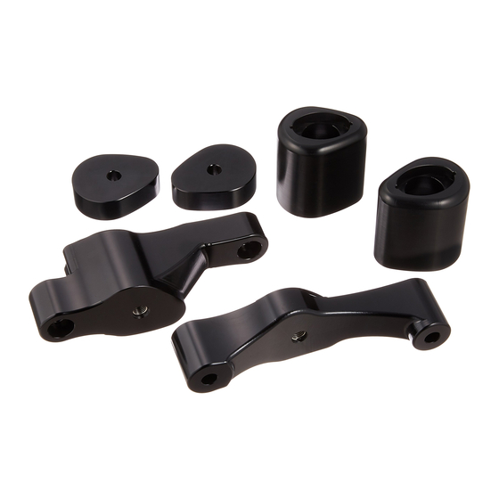
FITTING INSTRUCTIONS FOR CP0417BL
AERO CRASH PROTECTORS FOR KAWASAKI Z1000SX '17- NON-DRILL KIT
Picture A
Picture B
THIS KIT CONTAINS THE ITEMS PICTURED AND LABELLED BELOW.
DO NOT PROCEED UNTIL YOU ARE SURE ALL PARTS ARE PRESENT.
Please note that the way the kit is packed does not necessarily represent the way of mounting to the
bike.
T
(
).
HE PARTS SHOWN MAY BE REPRESENTATIVE ONLY
FOR CLARITY OF INSTRUCTIONS ONLY
LEFT SIDE
R&G Racing
Unit 1, Shelley's Lane, East Worldham, Alton, Hampshire, GU34 3AQ
Tel: +44 (0)1420 89007 Fax: +44 (0)1420 87301
www.rg-racing.com
Email:
info@rg-racing.com
Publicité

Manuels Connexes pour R&G CP0417BL


Sommaire des Matières pour R&G CP0417BL
- Page 1 CP0417 FITTING INSTRUCTIONS FOR CP0417BL AERO CRASH PROTECTORS FOR KAWASAKI Z1000SX ’17- NON-DRILL KIT Picture A Picture B THIS KIT CONTAINS THE ITEMS PICTURED AND LABELLED BELOW. DO NOT PROCEED UNTIL YOU ARE SURE ALL PARTS ARE PRESENT. Please note that the way the kit is packed does not necessarily represent the way of mounting to the bike.
-
Page 2: Right Side
CP0417 RIGHT SIDE LEGEND ITEM 1 = CRASH PROTECTOR CAPS (BC0002) (x2). ITEM 2 = M10 x 1.25 x 80mm LONG HEX HEAD BOLTS (x2). ITEM 3 = M10 x 19mm OD WASHERS (x2). ITEM 4 = LOCK-WASHERS (LW0001) (x2). ITEM 5 = M10 x 1.25 x 100mm LONG CAP HEAD BOLTS (x3). - Page 3 CP0417 TOWARDS REAR TOWARDS FRONT OF BIKE OF BIKE PICTURE C GENERAL TORQUE SETTINGS M4 BOLT = 8Nm M5 BOLT = 12Nm M6 BOLT = 15Nm M8 BOLT = 20Nm M10 BOLT = 40Nm Picture 1 Picture 2 Picture 3 Picture 4 R&G Racing Unit 1, Shelley’s Lane, East Worldham, Alton, Hampshire, GU34 3AQ...
- Page 4 CP0417 Picture 5 Picture 6 Picture 7 Picture 8 Picture 9 Picture 10 R&G Racing Unit 1, Shelley’s Lane, East Worldham, Alton, Hampshire, GU34 3AQ Tel: +44 (0)1420 89007 Fax: +44 (0)1420 87301 www.rg-racing.com Email: info@rg-racing.com...
- Page 5 CP0417 Picture 11 Picture 12 Picture 13 Picture 14 Picture 15 Picture 16 R&G Racing Unit 1, Shelley’s Lane, East Worldham, Alton, Hampshire, GU34 3AQ Tel: +44 (0)1420 89007 Fax: +44 (0)1420 87301 www.rg-racing.com Email: info@rg-racing.com...
- Page 6 CP0417 Picture 17 Picture 18 Picture 19 Picture 20 Picture 21 Picture 22 R&G Racing Unit 1, Shelley’s Lane, East Worldham, Alton, Hampshire, GU34 3AQ Tel: +44 (0)1420 89007 Fax: +44 (0)1420 87301 www.rg-racing.com Email: info@rg-racing.com...
-
Page 7: Fitting Instructions
CP0417 Picture 23 Picture 24 FITTING INSTRUCTIONS Right side (as you sit on the bike) To fit the crash protectors first the fairings must be removed. To do this, start by removing the upper side panel that is arrowed in picture 1. Remove the bolt that is shown in picture 2 and the push rivet that is arrowed in picture 3, before removing from the rubber mount shown in picture 4. - Page 8 CP0417 Remove the side infill panel by removing the two bolts and then the infill panel can be pulled off its rubber mount and removed from the bike. Disconnect the connector for the indicator wiring. Remove the three bolts on the main side fairing and on the inside of the side fairing, remove the two push rivets that connect the fairing to the inner radiator cowl plastic, before removing the fairing from the bike.
- Page 9 CP0417 Digital copies of these instructions are available to download from www.rg-racing.com CONSUMER NOTICE The catalogue description and any exhibition of samples are only broad indications of the Products and R&G may make design changes which do not diminish their performance or visual appeal and supplying them in such state shall conform to the order. The Buyer acknowledges no representation or warranty (other than as to title) has been given or will apply to the Products other than those in R&G’s order or confirmation and the Buyer confirms it has chosen the Products as being of merchantable quality and suitable for its particular purposes.
- Page 10 CP0417 NOTICE DE MONTAGE POUR CP0417BL PROTECTIONS CRASH POUR KAWASAKI Z1000SX ’17- KIT NON PERCE Photo A Photo B E KIT CONTIENT LES ARTICLES EXPOSES CI DESSOUS VERIFIER QUE TOUTES LES PIECES SOIENT PRESENTES AVANT DE PROCEDER AU MONTAGE La façon dont le kit est emballé ne correspond pas forcément à la façon de monter les pièces sur...
-
Page 11: Outils Requis
CP0417 COTE DROIT LEGENDE ARTICLE 1 = CAPUCHONS DE PROTECTION CRASH (BC0002) (x2). ARTICLE 2 = M10 x 1.25 x 80mm BOULONS (x2). ARTICLE 3 = M10 x 19mm RONDELLES (x2). ARTICLE 4 = RONDELLES DE BLOCAGE (LW0001) (x2). ARTICLE 5 = M10 x 1.25 x 100mm BOULONS (x3). ARTICLE 6 = M10 x 16mm RONDELLES (x4). - Page 12 CP0417 ARRIÈRE MOTO AVANT MOTO PHOTO ‘C’ OUPLES DE SERRAGE RECOMMANDES M4 BOULON = 8Nm M5 BOULON = 12Nm M6 BOULON = 15Nm M8 BOULON = 20Nm M10 BOULON = 40Nm Photo 1 Photo 2 R&G Racing Unit 1, Shelley’s Lane, East Worldham, Alton, Hampshire, GU34 3AQ Tel: +44 (0)1420 89007 Fax: +44 (0)1420 87301 www.rg-racing.com Email:...
- Page 13 CP0417 Photo 3 Photo 4 Photo 5 Photo 6 Photo 7 Photo 8 R&G Racing Unit 1, Shelley’s Lane, East Worldham, Alton, Hampshire, GU34 3AQ Tel: +44 (0)1420 89007 Fax: +44 (0)1420 87301 www.rg-racing.com Email: info@rg-racing.com...
- Page 14 CP0417 Photo 9 Photo 10 Photo 11 Photo 12 Photo 13 Photo 14 R&G Racing Unit 1, Shelley’s Lane, East Worldham, Alton, Hampshire, GU34 3AQ Tel: +44 (0)1420 89007 Fax: +44 (0)1420 87301 www.rg-racing.com Email: info@rg-racing.com...
- Page 15 CP0417 Photo 15 Photo 16 Photo 17 Photo 18 Photo 19 Photo 20 R&G Racing Unit 1, Shelley’s Lane, East Worldham, Alton, Hampshire, GU34 3AQ Tel: +44 (0)1420 89007 Fax: +44 (0)1420 87301 www.rg-racing.com Email: info@rg-racing.com...
- Page 16 CP0417 Photo 21 Photo 22 Photo 23 Photo 24 NOTICE DE MONTAGE: Coté droit (assis sur la moto) Pour monter les protections crash, commencez par enlever les carénages. Pour cela, commencer par enlever le panneau supérieur latéral indiqué sur la photo 1. Enlever le boulon indiqué sur la photo 2 et le rivet indiqué...
- Page 17 CP0417 A l’intérieur des carénages latéraux, enlever les 2 rivets qui connectent le carénage à l'intérieur du capot du radiateur en plastique, voir photos 16 & 17. Le carénage peut maintenant être enlevé de la moto. Enlever les 2 boulons moteur/cadre du coté droit de la moto, voir photo 18. ...
- Page 18 CP0417 Glisser une rondelle de blocage crantée (article 4) sur le boulon de façon à ce qu’elle se place contre la rondelle tout juste insérée. Ensuite, insérer le boulon avec ses rondelles dans la protection crash (article 11) de façon à ce que la tête du boulon et les rondelles se placent dans le contre alésage.