Publicité

Les langues disponibles

Les langues disponibles

Liens rapides

Montage- und Bedienungsanleitung
Installation and operating manual
Instructions de montage et mode d'emploi Page
®
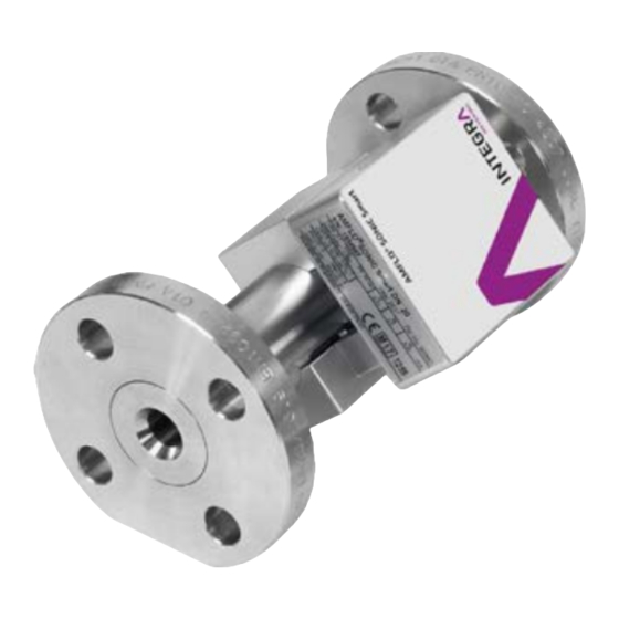
AMFLO
SONIC Smart
Durchflussgeber für Fernwärme
Flow transmitter for district heating
Débitmètre pour chauffage urbain
Seite
3 - 18
Page
19 - 34
35 - 49

Publicité

Table des Matières
loading

Sommaire des Matières pour INTEGRA Metering AMFLO SONIC Smart

  • Page 1 Montage- und Bedienungsanleitung Seite 3 - 18 Installation and operating manual Page 19 - 34 Instructions de montage et mode d’emploi Page 35 - 49 ® AMFLO SONIC Smart Durchflussgeber für Fernwärme Flow transmitter for district heating Débitmètre pour chauffage urbain...
  • Page 2: Table Des Matières

    Inhaltsverzeichnis 1 Sicherheit 2 Lieferumfang und Zubehör 3 Installation 4 Bedienung und Betrieb 5 Störung und Fehlermeldung 6 Ausserbetriebnahme, Demontage und Entsorgung 7 Eichung 8 Technische Daten 9 Anhang Table of contents 1 Safety 2 Scope of Supply and Accessories 3 Installation 4 Operation 5 Troubleshooting...
  • Page 3: Sicherheit

    Sicherheit 1.1 Bestimmungsgemässe Verwendung ® Das Gerät AMFLO SONIC Smart ist ausschliesslich als Durchflussgeber von Wasser in Heiz- und Kühlkreisläufen bestimmt. Dieses Gerät ist für die Erfassung, Berechnung und Versendung von Informationen zu Volumenströmen innerhalb der angegebenen Spezifi- kationen ausgelegt. Eine unsachgemässe oder nicht bestimmungsgemässe Verwendung kann dazu führen, dass die Betriebssicherheit des Geräts nicht mehr gewährleistet ist.
  • Page 4 1.3 Sicherheitshinweise und Vorsichtsmassnahmen Der Hersteller übernimmt keinerlei Verantwortung, wenn die folgenden Sicherheitsvor- schriften und Vorsichtsmassnahmen missachtet werden: • Änderungen am Gerät, die ohne vorherige schriftliche Zustimmung vom Hersteller umgesetzt werden, führen zur sofortigen Beendigung der Produkthaftung und Ge- währleistung. •...
  • Page 5: Lieferumfang Und Zubehör

    HINWEIS Diese Installationsanleitung ist für qualifiziertes Personal gedacht und enthält daher keine grundlegenden Arbeitsschritte. Vor Inbetriebnahme des Gerätes oder Systems muss diese Montage- und Betriebsanleitung vollständig gele- sen und verstanden werden. Bewahren Sie diese Anleitung zum späteren Nachschlagen auf! 1.5 Handhabung, Transport und Lagerung Wir beglückwünschen Sie zum Erwerb dieses hochwertigen Messgerätes.
  • Page 6: Installation

    Anzahl Materialbeschreibung Bildbeschreibung ® Durchflussgeber AMFLO SONIC Smart Anschlusskabel 2.5 m Flachdichtungen (bei Flanschausführung) Schutzhaube Montage und Bedienungsanleitung Installation VORSICHT Die Oberfläche des Gerätes/Systems und das Medium können heiss sein. Verbrennungsgefahr! • Nur an abgekühlten Geräten/ Systemen arbeiten. • Arbeiten dürfen nur von autorisierten Fachkräften gemäss den gelten- den Vorschriften durchgeführt werden.
  • Page 7 WARNUNG Das Gerät/System kann unter Druck stehen. Schwere Verletzungsgefahr! • Nur an Geräten/Systemen arbeiten, die vom Druck entlastet sind. • Bei Arbeiten am Gerät/System auf austretendes Medium achten. • Arbeiten dürfen nur von autorisierten Fachkräften gemäss den gelten- den Vorschriften durchgeführt werden. •...
  • Page 8 Horizontaler und vertikaler Einbau möglich horizontal vertikal zu vermeiden Empfehlung Die Montage des Durch- In Anlagen mit an das Gerät fluss- messers in langen anschliessenden langen Leitungen ohne Abstützun- Leitun- gen sollten schwin- gen ist zu vermeiden. gungshem- mende schlussstücke ver- wendet werden.
  • Page 9: Mechanische Installation

    3.2 Mechanische Installation WARNUNG Leckage oder Bruch durch unsachgemässe mechanische Installation. Schwere Verletzungsgefahr! Risiko erheblichen Sachschadens! • Versuchen Sie niemals, Fehlstellungen an Abzweigstellen, Winkelstü- cken, zu grossen Längsabständen oder Verdrehungen unter Anwen- dung von Gewalt zu überwinden. • Stellen Sie sicher, dass die Rohrleitungen flexibel genug sind. Sollte dies nicht möglich sein, müssen Kompensatoren verwendet werden.
  • Page 10: Elektrische Installation

    3.3 Elektrische Installation HINWEIS Falscher elektrischer Anschluss an Netzspannung und/oder Verbindungen zu anderen Systemen. Gefahr von Fehlfunktionen oder Beschädigungen! • Überprüfung der technischen Daten, Kapitel 8 3.3.1. Anschluss VORSICHT Maximale Kabellänge 10 m aufgrund EMV-Richtlinie. DIN M12 5 Pin Stecker am Gerät Adernfarbe Funktion Standardkabel:...
  • Page 11: Stromversorgung

    3.3.2. Stromversorgung VORSICHT Die Spannungsbereich muss eingehalten werden. Pin: 1 und 3 4 - 24V DC nach EN 1434. 3.3.3. Impulsausgang Pin: 2 und 4 Modus: passiv (solid state relais) Max. Strom/max. Spannung: 50 mA / 48 V Max. Ausgangsfrequenz: 200 Hz Nennweite DN Zoll ½...
  • Page 12: Bedienung Und Betrieb

    Bedienung und Betrieb HINWEIS Für die ordnungsgemässe Funktion muss das Gerät korrekt an eine Spannungs- versorgung angeschlossen und das Messrohr komplett gefüllt sein. 4.1 Anzeige Die Anzeige LEDs dienen der Durchflussindentifikation. ANMERKUNG An der Oberseite der Elektronikeinheit befinden zwei LEDs zur Betriebs- und/o- der Fehleranzeige mit den folgenden drei Möglichkeiten: grüne LED blinkt bzw.
  • Page 13: Ausserbetriebnahme, Demontage Und Entsorgung

    Keine Ausgangsimpulse Ist das Gerät an die Stromversorgung angeschlossen worden? Keine LED blinkt Entspricht die Spannung den Spezifikationen? Ist die Leitung teilgefüllt oder leer? Falsche Durchflussrichtung? Falsche Verdrahtung? Instabile Messungen Ist die Durchflussmenge stabil? Liegt die Strömungsgeschwindigkeit oder Durchflussmenge ausserhalb der Spezifikation? Ist die Leitung teilgefüllt oder leer? Sind Gasblasen im Medium? Ausserbetriebnahme, Demontage und Entsorgung...
  • Page 14: Entsorgung

    6.2 Entsorgung Am Ende des Lebenszyklus sollte dieses Produkt entsprechend den lokalen Vorschriften der Wiederverwertung oder Beseitigung zugeführt werden. Batterien und Akkus entfernen und separat entsorgen. Die getrennte Sammlung und das Recycling von Altgeräten hilft, natürliche Ressourcen zu schonen und sicherzustellen, dass sie in einer Weise entsorgt werden, die den Schutz von Umwelt und Natur gewährleisten.
  • Page 15: Technische Daten

    Technische Daten Nennweite DN 20 – 40 Flüssigkeit Wasser nach Europäische Empfehlung CEN/TR 16911 (max. pH 10,5) Nenndruck PN 40 (Flansch); PN 16 (Gewinde) Material Messrohr: Edelstahl (Typ 1.4404/316(L) Flansch: Edelstahl (Typ 1.4307/304L oder 1.4404/316) Temperatur Medium = 1 - 130 °C Fluid Temperatur Umgebung = 5 - 55 °C...
  • Page 16 8.2 Abmessungen und Geräteanschluss Nennweite DN Zoll ¾ 1 ¼ 1½ Gewicht...
  • Page 17 8.3 Messfehlergrenze 8.4 Druckverlust...
  • Page 18 8.5 Messgenauigkeit EN1434 Klasse 2 (typischerweise ±1% bei ≥ 0.5 m/s und Messgenauigkeit ±0.005 m/s bei < 0.5 m/s) Referenzbedingungen Flüssigkeitstemperatur 20 °C Statischer Flüssigkeitsdruck >3 bar Umgebungstemperatur 23 °C Vorwärmzeit des Gerätes 15 min Flüssigkeit Wasser...
  • Page 19: Safety

    Safety 1.1 Intended Use ® The device AMFLO SONIC Smart is designed and solely intended for the use as flow transmitter for water in heating and cooling cicuits. Improper or non-intended use of the device may compromise operational reliability of the device.
  • Page 20: Safety Rules And Precautions

    1.3 Safety rules and precautions The manufacturer accepts no responsibility if the following safety rules and precautions are disregarded: • Any modifications of the device implemented without the prior written consent of the manufacturer will result in the immediate termination of product liability and warranty.
  • Page 21: Returning Devices

    NOTICE This installation manual is intended for qualified personnel and therefore does not include basic working steps. Before operating the equipment or system, this installation and operating manual must be completely read and under- stood. Please retain this manual for future reference! 1.5 Handling, transport and storage Thank you for purchasing this high-quality measuring device.
  • Page 22: Installation

    Quan- Material description Image description tity ® Flow transmitter AMFLO SONIC Smart Connection cable 2.5 m Flat seals (for flange version) Protective cover Installation and operating instructions Installation CAUTION The surfaces of the device/system and the medium may be hot. Risk of burns! •...
  • Page 23 WARNING The device/system may be under pressure. Risk of severe injury! • Carry out work only on non-pressurised systems. • When working on the device/system, watch out for leaking medium. • Work may only be performed by authorised specialists in accordance with the applicable regulations.
  • Page 24 Horizontal and vertical installation possible horizontal vertical To prevent Recommendation The installation of the flow In plants with long pipes di- meter in long pipes without rectly connected to the de- support has to be pre- vice vibration damping con- vented.
  • Page 25: Mechanical Installation

    3.2 Mechanical installation WARNING Leakage or rupture due to improper mechanical installation. Risk of severe injury! Risk of substantial property damage! • Never attempt to overcome misalignments (lateral, angular, longitudinal, torsional) using force. • Make sure the piping is flexible enough; if not, use compensators. •...
  • Page 26: Electrical Installation

    3.3 Electrical installation NOTICE Incorrect electrical connection to the mains voltage and/or connections to other systems. Risk of malfunction or damage! • Check the technical data, section 8 3.3.1. Attachment CAUTION Maximum cable length 10 m due to the EMC Directive. DIN M12 5 pin connector at the device Core colour...
  • Page 27: Power Supply

    3.3.2. Power supply NOTICE The voltage range needs to be adhered to. Pin: 1 and 3 4 - 24 VDC (max. power 10 mA) complies at least with EN 1434. 3.3.3. Pulse output Pin: 2 and 4 Mode: passive (solid state relais) Max.
  • Page 28: Operation

    Operation NOTICE For proper function the device has to be properly connected to a power supply and the measuring pipe must be filled completely. 4.1 Display The displayed LEDs are used for flow identification. NOTE At the top of the electronic unit two LEDs for operation and/or error signalisation are located, which have the following three options: Green LED is blinking or lighted: flow indication analogue to output pulse...
  • Page 29: Troubleshooting

    Troubleshooting Problem Possible reasons No output pulse Is the device connected to the power supply? No LED blinking Is the voltage complying with the specifications? Is the pipe partially filled or empty? Wrong flow direction? Wrong wiring? Instable measuring Is the flow amount stable? Is the flow speed or flow amount out of specification? Is the pipe partially filled or empty? Are gas bubbles in the medium?
  • Page 30: Calibration

    6.1 Decommissioning • Disconnect all sources of energy. • Remove the device from the system. 6.2 Disposal At the end of its life cycle, this product should be disposed of according to local regulations regarding waste recycling or disposal. Batteries and rechargeable batteries shall be recycled separately. The separate collection and recycling of used products will help to conserve natural re- sources, and ensures that they are disposed of in a way that does not cause damage to the environment and nature.
  • Page 31: Technical Data

    Technical Data Nominal diameter DN 20 - 40 Liquid Water according to European recommendation CEN/TR 16911 (max. pH 10.5) Nominal pressure PN 40 (flange); PN 16 (thread) Material Pipe: stainless steel (typ 1.4404/316L) Flange: stainless steel (typ 1.4307/304L or 1.4404/316) Temperature range liquid = 0 - 130 °C Fluid...
  • Page 32 8.2 Dimensions and device port Nominal diameter DN Zoll ¾ 1 ¼ 1½ Weight...
  • Page 33: Pressure Loss

    8.3 Measuring Error 8.4 Pressure loss...
  • Page 34 8.5 Measuring accuracy EN1434 Class 2 (typically ±1 % at ≥ 0.5 m/s and ±0.005 m/s Measuring accuracy below 0.5 m/s) Reference conditions Liquid temperature 20 °C Static liquid pressure >3 bar Ambient temperature 23 °C Preheating time of the device 15 min Liquid Water...
  • Page 35: Sécurité

    Sécurité 1.1 Utilisation conforme ® L’appareil AMFLO SONIC Smart est prévu uniquement pour mesurer le débit d’eau dans des circuits de chauffage et de refroidissement. En cas d’utilisation incorrecte ou non con- forme, la sûreté opérationnelle de l’appareil n’est plus garantie. Le fabricant décline toute responsabilité...
  • Page 36: Consignes De Sécurité Et Mesures De Précaution

    1.3 Consignes de sécurité et mesures de précaution Le fabricant décline toute responsabilité en cas de non-respect des consignes de sécurité et des mesures de précaution indiquées ci-après: • Toute modification apportée à l’appareil sans l’autorisation écrite préalable du fa- bricant entraîne l’annulation immédiate de la responsabilité...
  • Page 37: Renvoi D'appareils

    AVIS Ce manuel d’installation a été conçu pour un personnel qualifié et ne décrit donc pas les étapes de travail de base. Avant de procéder à la mise en ser- vice de l’appareil ou du système, la personne concernée doit avoir lu et com- pris intégralement le présent manuel de montage et d’utilisation.
  • Page 38: Contenu De La Livraison Et Accessoires

    Contenu de la livraison et accessoires Le contenu de la livraison est mentionné le bulletin livraison. S'il vous plaît vérifier tous les composants et pièces fournies après la réception de la marchandise. Avaries de transport doit être signalé immédiatement! Nombre Description matérielle Image desciption ®...
  • Page 39 AVERTISSEMENT L’appareil/le système peut être sous pression. Risque de graves brûlures! • Travaillez uniquement avec des appareils/systèmes qui ne sont plus sous pression. • Lors de tout travail sur l’appareil/le système, faites attention aux fuites de liquide. • Les travaux doivent uniquement être effectués par des spécialistes autorisés, dans le respect des prescriptions en vigueur.
  • Page 40 Possibilité de montage horizontal et vertical horizontal vertical à éviter recommandation Il faut éviter d’installer le Dans les installations com- débitmètre sur de longs portant de longs tuyaux rac- tuyaux sans étais. cordés à l’appareil, il faut uti- liser des raccords antivibra- tiles.
  • Page 41: Installation Mécanique

    3.2 Installation mécanique AVERTISSEMENT Fuite ou rupture suite à une installation mécanique non conforme. Risque de graves brûlures! Risque de dommage matériel considérable! • Ne tentez jamais de recourir à la force pour rectifier des mauvaises po- sitions sur des points de bifurcation, pour enlever des pièces d’angle, réduire des écarts longitudinaux trop importants ou supprimer des défor- mations.
  • Page 42: Installation Électrique

    3.3 Installation électrique AVIS Raccordement électrique non conforme à la tension de réseau et/ou liaisons avec d’autres systèmes. Risque de dysfonctionnement ou de dommages! • Vérification des données techniques, chapitre 8, page __ 3.3.1. Connexion ATTENTION Longueur maximale du câble 10 m en raison de la directive CEM. Fiche à...
  • Page 43: Alimentation En Courant

    3.3.2. Alimentation en courant ATTENTION La plage de tension doit être respectée. Broche: 1 et 3 3 - 24 VDC répondant au moins à EN 1434. 3.3.3. Sortie d’impulsions Broche: 2 et 4 Mode: passiv (solid state relais) Puissance maxi./tension maxi.: 50 mA / 48 V Fréquence de sortie maxi.: 200 Hz Largeur nominale pouces...
  • Page 44: Utilisation Et Fonctionnement

    Utilisation et fonctionnement AVIS Pour garantir le bon fonctionnement, l’appareil doit être branché correctement à une alimentation électrique et le tube de mesure doit être entièrement rempli. 4.1 Affichage Les voyants indicateurs sont utilisés pour l’identification du débit. REMARQUE Il y a deux LED d’indication de fonctionnement et/ou d’erreurs sur la face supérieure de l’unité...
  • Page 45: Mise Hors Service, Démontage Et Élimination

    Le tuyau est-il partiellement rempli ou vide? Mauvais sens de circulation? Mauvais câblage? Mesures instables Le débit est-il stable? Vitesse du flux ou débit en-dehors des spécifications? Le tuyau est-il partiellement rempli ou vide? Y-a-t-il des bulles de gaz au niveau du médium? Mise hors service, démontage et élimination ATTENTION La surface de l’appareil/du système et le fluide peuvent être chauds.
  • Page 46: Élimination

    6.2 Élimination À la fin du cycle de vie, ce produit doit être acheminé vers les filières de recyclage ou d’élimination conformément aux prescriptions locales. Retirez les piles et les batteries rechargeables et les éliminer séparément. La collecte séparée et le recyclage d’appareils usagés contribuent à la préservation des ressources naturelles et garantissent une élimination du produit dans le respect de la na- ture et de l’environnement.
  • Page 47: Données Techniques

    Données techniques Diamètre nominal DN 20 – 40 Liquide selon la recommandation européenne CEN/TR 16911 (pH max. 10,5) Pression nominale PN 40 (bride); PN 16 (filetage) matière le tube de mesure: Acier inoxydable (type 1.4404/316(L) bride: Acier inoxydable (type 1.4307/304L ou 1.4404/316) Plage de températures liqu.
  • Page 48: Dimensions Et Branchement De L'appareil

    8.2 Dimensions et branchement de l’appareil Largeur nominale DN pouces ¾ 1 ¼ 1½ Poids...
  • Page 49: Limites D'erreur De Mesure

    8.3 Limites d'erreur de mesure 8.4 Perte de charge...
  • Page 50: Précision Des Mesures

    8.5 Précision des mesures EN1434 classe 2 (typique ±1% à ≥ 0.5 m/s et ±0.005 m/s à < Précision des mesures 0.5 m/s) Conditions de référence Température du liquide 20 °C Pression statique du liquide >3 bar Température ambiante 23 °C Temps de préchauffage de l’appa- 15 min reil...
  • Page 51 Anhang / Appendix / Annexe...
  • Page 52 info@ integra -metering.com www.integra-metering.com...

Table des Matières