R&G LP0203BK Mode D'emploi
Les langues disponibles
Les langues disponibles
Liens rapides
FITTING INSTRUCTIONS FOR LP0203BK LICENCE PLATE BRACKET
TRIUMPH STREET TWIN '16-
Page | 1
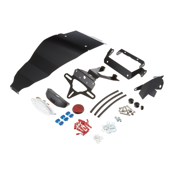
THIS KIT CONTAINS THE ITEMS PICTURED AND LABELLED BELOW.
DO NOT PROCEED UNTIL YOU ARE SURE ALL PARTS ARE PRESENT.
Please note that the way the kit is packed does not necessarily represent the way of mounting to the bike.
T
(
).
HE PARTS SHOWN MAY BE REPRESENTATIVE ONLY
FOR CLARITY OF INSTRUCTIONS ONLY
x2
x4
x2
x2
x2
x2
R&G Racing
Unit 1, Shelley's Lane, East Worldham, Alton, Hampshire, GU34 3AQ
Tel: +44 (0)1420 89007 Fax: +44 (0)1420 87301
www.rg-racing.com
Email:
info@rg-racing.com

Manuels Connexes pour R&G LP0203BK


Sommaire des Matières pour R&G LP0203BK
- Page 15 NOTICE DE MONTAGE POUR LP0203BK SUPPORT DE PLAQUE TRIUMPH STREET TWIN ’16- Page | 15 Le kit contient les articles exposés ci-dessous, vérifier que toutes les pièces soient présentes avant de procéder au montage. A FAÇON DONT LE KIT EST EMBALLE NE CORRESPOND PAS FORCEMENT A LA FAÇON DE MONTER LES PIECES...
- Page 16 Page | 16 LEGENDE ARTICLE 1 = LA0003 FEU DE PLAQUE (x1). ARTICLE 2 = LA0003 LINCEUL (x1). ARTICLE 3 = SUPPORT DE PLAQUE (TB0203 Partie 1) (x1). ARTICLE 4 = ENTRETOISE FILETEE (S0977 – 12mm DE LONG) (x1). ARTICLE 5 = M6 RONDELLES (20mm OD) (x5). ARTICLE 6 = M6 ECROUS (x4).
-
Page 17: Outils Requis
OUTILS REQUIS • Clés Allen 4, 5 & 6mm. • Clés Torx T20 & T30. • Clés à douille 6, 8, 10 & 13mm. • Page | 17 Pince coupante. Couples de serrage recommandés : M4 BOULON = 8Nm M5 BOULON = 12Nm M6 BOULON = 15Nm M8 BOULON = 20Nm NOTICE DE MONTAGE :... - Page 18 Si installation de l’option clignotant fixé le plus vers l’arrière • Prendre le support de clignotant le plus à l’arrière (article 19 – TB0203 Partie 3) et montez les clignotants de votre choix en passant les fils dans le trou le plus large du support de clignotant et en plaçant le trou du clignotant dans le trou, voir photo 21.
- Page 19 l’arrière du trou fileté qui fixe l’absorbeur de choc arrière en place. Notez qu’il est peu probable que ce cache se monte si la moto possède des barres d’appui, fixées sur ce même boulon. • Veiller à ce que les fils soient bien rangés à l’arrière de la moto, pour le clignotant et le feu de plaque, voir photo Si installation de l’option clignotant monté...
- Page 20 • Répétez la procédure ci-dessus pour le clignotant du côté opposé. • Enlever le boulon M6 x 35mm restant et la rondelle qui ont précédemment été insérés à travers le cache de sous siège et le croisillon de sous cadre, voir photo 34, puis positionner les 2 boulons M6 x 35mm et rondelles dans les 2 trous de fixation sur le support clignotant par-dessous, en veillant à...