Dea NET24N Notice D'emploi Et Avertissements

Dea NET24N Notice D'emploi Et Avertissements

Armoire de commande programmable
Table des Matières

Publicité

Les langues disponibles
  • FR

Les langues disponibles

  • FRANÇAIS, page 71
NET24N
Quadro di comando programmabile
Istruzioni d'uso ed avvertenze
Programmable control board
Operating instructions and warnings
Armoire de commande programmable
Notice d'emploi et avertissements
Cuadro de maniobra programable
Instrucciones de uso y advertencias
Quadro de comando programável
Instruções para utilização e advertências
Uniwersalna centrala sterująca
Instrukcja montażu i użytkowania

Publicité

Table des Matières
loading

Sommaire des Matières pour Dea NET24N

  • Page 1 NET24N Quadro di comando programmabile Istruzioni d’uso ed avvertenze Programmable control board Operating instructions and warnings Armoire de commande programmable Notice d’emploi et avertissements Cuadro de maniobra programable Instrucciones de uso y advertencias Quadro de comando programável Instruções para utilização e advertências Uniwersalna centrala sterująca...
  • Page 2 : •Modello: NET24N (Sc he d a e l et t r o ni ca u ni v e r s a l e 2 4V ) •Tipo: NET24N...
  • Page 3: Table Des Matières

    ATTENZIONE DEA System ricorda che la scelta, la disposizione e l’installazione di tutti i dispositivi ed i materiali costituenti l’as- sieme completo della chiusura, devono avvenire in ottemperanza alle Direttive Europee 2006/42/CE (Direttiva macchine), 2004/108/ CE (compatibilità...
  • Page 4: Descrizione Prodotto

    2 DESCRIZIONE DEL PRODOTTO NET24N è un quadro di comando universale per automazioni DEA System ad 1 o 2 motori 24V con o senza encoder. La caratteristica principale di questa centrale è la semplicità di configurazione di ingressi e uscite secondo la propria esigenza garan- tendo in questo modo l’adattabilità...
  • Page 5: Configurazione

    CONFIGURAZIONE DELLA CENTRALE La centrale di comando universale Net24N può essere utilizzata per la gestione dei seguenti tipi ( ) di chiusure motorizzate DEA System: cancelli a battente, scorrevoli, porte basculanti e barriere veicolari. Al fine di garantire la massima adattabilità a ciascun tipo (...
  • Page 7 CONFIGURAZIONE CANCELLI SCORREVOLI COLLEGAMENTI ELETTRICI Eseguire i collegamenti elettrici seguendo le indicazioni della “Tabella 1” e lo schema di pag. 6. Tabella 1 “collegamento alle morsettiere” Uscita +24 V alimentazione ausiliari max 200mA Ingresso alimentazione 22 V ~ da trasformatore Ingresso alimentazione 24 V da batteria o da accumulatore fotovoltaico Green Energy (fare attenzione alla polarità).
  • Page 8 ROSSO...
  • Page 9: Scorrere I Parametri Con I Tasti

    PROGRAMMAZIONE STANDARD Alimentazione Dare alimentazione, sul display compaiono in sequenza le scritte “ ”, “ ”, “ ” seguite dal simbolo di cancello chiuso “----” Nel caso in cui la centrale sia già stata programmata e la riaccensione sia dovuta ad una interruzione dell’alimentazione, al primo impulso di START, verrà...
  • Page 10 Selezione senso di marcia 1. Scorrere i parametri con i tasti fino a visua- lizzare sul display P063; 2. Accedere al parametro premendo il tasto 3. Agendo sui tasti , impostare: - d000=motore in posizione standard (a sinistra del varco); - d001=motore in posizione invertita (a destra del varco;...
  • Page 11 7.2 Apprendimento 1. Scorrere i parametri con i tasti fino a visualizzare sul display P005; 2. Accedere al parametro premendo il tasto 3. Alla scritta “ ” lampeggiante premere un tasto del radiocomando da memorizzare; 4. Sul display apparirà la sigla del radioco- mando appena memorizzato e successiva- mente “...
  • Page 13 CONFIGURAZIONE CANCELLI A BATTENTE COLLEGAMENTI ELETTRICI Eseguire i collegamenti elettrici seguendo le indicazioni della “Tabella 1” e lo schema di pag. 12. Tabella 1 “collegamento alle morsettiere” Uscita +24 V alimentazione ausiliari max 200mA Ingresso alimentazione 22 V ~ da trasformatore Ingresso alimentazione 24 V da batteria o da accumulatore fotovoltaico Green Energy (fare attenzione alla polarità).
  • Page 14 ROSSO ROSSO BIANCO BIANCO VERDE VERDE MARRONE MARRONE...
  • Page 15 PROGRAMMAZIONE STANDARD Alimentazione Dare alimentazione, sul display compaiono in sequenza le scritte “ ”, “ ”, “ ” seguite dal simbolo di cancello chiuso “----” Nel caso in cui la centrale sia già stata programmata e la riaccensione sia dovuta ad una interruzione dell’alimentazione, al primo impulso di START, verrà...
  • Page 16 Selezione funzionamento 1 o 2 motori 1. Scorrere i parametri con i tasti fino a visualizzare sul display P030; 2. Accedere al parametro premendo il tasto 3. Agendo sui tasti , impostare: - d001=per la funzione a motore singolo; - d002=per la funzione a 2 motori; 4.
  • Page 17 7.2 Apprendimento 1. Scorrere i parametri con i tasti fino a visualizzare sul display P005; 2. Accedere al parametro premendo il tasto 3. Alla scritta “ ” lampeggiante premere un tasto del radiocomando da memorizzare; 4. Sul display apparirà la sigla del radioco- mando appena memorizzato e successiva- mente “...
  • Page 19 CONFIGURAZIONE BASCULANTI COLLEGAMENTI ELETTRICI Eseguire i collegamenti elettrici seguendo le indicazioni della “Tabella 1” e lo schema di pag. 18. Tabella 1 “collegamento alle morsettiere” Uscita +24 V alimentazione ausiliari max 200mA Ingresso alimentazione 22 V ~ da trasformatore Ingresso alimentazione 24 V da batteria o da accumulatore fotovoltaico Green Energy (fare attenzione alla polarità).
  • Page 20 ROSSO ROSSO ROSSO ROSSO MARRONE MARRONE VERDE VERDE BIANCO BIANCO...
  • Page 21 PROGRAMMAZIONE STANDARD Alimentazione Dare alimentazione, sul display compaiono in sequenza le scritte “ ”, “ ”, “ ” seguite dal simbolo di cancello chiuso “----” Nel caso in cui la centrale sia già stata programmata e la riaccensione sia dovuta ad una interruzione dell’alimentazione, al primo impulso di START, verrà...
  • Page 22: Concludere La Memorizzazione, Attendendo 10 Sec Fino Alla Visualizzazione Sul Display Della Scritta

    Apprendimento corsa motori 1. Scorrere i parametri con i tasti fino a visualizzare sul display P003; 2. Accedere al parametro premendo il tasto 3. Alla scritta “ ” lampeggiante, tenere premuto il tasto 4. Rilasciare il tasto non appena la scritta “ ”...
  • Page 23: Scorrere Con I Tasti

    Modifica dei parametri di funzionamento Nel caso in cui sia necessario modificare i parametri di funziona- mento (es. forza, velocità, ecc..): 1. Scorrere con i tasti fino a visualizzare sul display il parametro desiderato (es. P032); 2. Accedere al parametro premendo il tasto 3.
  • Page 25 CONFIGURAZIONE BARRIERE COLLEGAMENTI ELETTRICI Eseguire i collegamenti elettrici seguendo le indicazioni della “Tabella 1” e lo schema di pag. 24 Tabella 1 “collegamento alle morsettiere” Uscita +24 V alimentazione ausiliari max 200mA Ingresso alimentazione 22 V ~ da trasformatore Ingresso alimentazione 24 V da batteria o da accumulatore fotovoltaico Green Energy (fare attenzione alla polarità).
  • Page 26 ROSSO ROSSO ROSSO ROSSO MARRONE MARRONE VERDE VERDE BIANCO BIANCO...
  • Page 27 PROGRAMMAZIONE STANDARD Alimentazione Dare alimentazione, sul display compaiono in sequenza le scritte “ ”, “ ”, “ ” seguite dal simbolo di cancello chiuso “----” Nel caso in cui la centrale sia già stata programmata e la riaccensione sia dovuta ad una interruzione dell’alimentazione, al primo impulso di START, verrà...
  • Page 28 Selezione funzionamento 1 o 2 motori 1. Scorrere i parametri con i tasti fino a visualizzare sul display P030; 2. Accedere al parametro premendo il tasto 3. Agendo sui tasti , impostare: - d001=per la funzione a motore singolo; - d002=per la funzione a 2 motori; 4.
  • Page 29 8.2 Apprendimento 1. Scorrere i parametri con i tasti fino a visualizzare sul display P005; 2. Accedere al parametro premendo il tasto 3. Alla scritta “ ” lampeggiante premere un tasto del radiocomando da memorizzare; 4. Sul display apparirà la sigla del radioco- mando appena memorizzato e successiva- mente “...
  • Page 31: Programmazione Avanzata

    5 PROGRAMMAZIONE AVANZATA Di seguito vengono aggiunte alcune procedure di programmazione relative alla gestione della memoria radiocomandi e di configu- razione avanzata degli ingressi di comando. Cancellazione radiocomandi memorizzati 1.1 Cancellazione di tutti i radiocomandi 1. Scorrere i parametri con i tasti fino a visualizzare sul display P004;...
  • Page 32: Confermare La Scelta Premendo Il Tasto

    3.2 Sblocco accesso alla programmazione 1. Scorrere i parametri con i tasti fino a vi- sualizzare sul display P008; 2. Accedere al parametro premendo il tasto 3. Il display visualizza in modo alterno le scritte ad indicare che la centrale è in atte- sa della trasmissione del codice di sblocco;...
  • Page 33 PROCEDURE DI PROGRAMMAZIONE PARAMETRI DI CONFIGURAZIONE INGRESSI...
  • Page 34 PARAMETRI CONFIGURAZIONE PARAMETRI DI FUNZIONAMENTO MOTORI...
  • Page 35 PARAMETRI DI FUNZIONAMENTO...
  • Page 36: Messaggi Visualizzati Sul Dispaly

    - Se la segnalazione si ripete, sostituire la centrale di comando. 7 COLLAUDO DELL’IMPIANTO Il collaudo è un’operazione essenziale al fine di verificare la corretta installazione dell’impianto. DEA System vuole riassumere il corretto collaudo di tutta l’automazione in 4 semplici fasi: ●...
  • Page 37 WARNING Using spare parts not indicated by DEA System and/or incorrect re-assembly can create risk to people, animals and property and also damage the product. For this reason, always use only the parts indicated by DEA System and scrupulously follow all assembly instructions.
  • Page 38: Product Description

    2 PRODUCT DESCRIPTION NET24N is a universal control panel for DEA System 1 or 2 24V operators automations with or without encoder. The main feature of this control board is its ease of configuration of inputs and outputs according to any needs thus ensuring adap- tability to any type of automation.
  • Page 39: Sliding Gates

    CONFIGURATION OF THE CONTROL PANEL The universal control unit Net24N can be used for the management of the following types ( ) of closures motorized by DEA System: swing and sliding gates, overhead doors and barriers. In order to ensure maximum adaptability to each...
  • Page 41 SLIDING GATES CONFIGURATION ELECTRICAL CONNECTIONS Execute the wiring following the directions of table 1 and diagrams on page 40 Table 1 “terminal board connections” +24 V power supply output for auxiliary devices 200mA 22 V ~ transformer power supply input 24 V battery power supply or photovoltaic accumulator Green Energy input (follow carefully polarity indications).
  • Page 42 BLUE...
  • Page 43 STANDARD PROGRAMMING Power Supply Give power supply, the display shows the following symbols “ ”, “ ”, “ ” and then “----”. If the control panel has already been programmed and the power fails or is switched off - once power is returned and a START com- mand is given, the position reset procedure is performed (see “rESP”...
  • Page 44 Selection of direction of motion 1. Scroll down the parameters with keys until you visualise P063; 2. Access the parameter by pressing the key; 3. Acting on keys, set: - d000=motor in standard position (on the left of the gap); - d001=motor in inverted position (on the right of the gap);...
  • Page 45 7.2 Learning 1. Scroll down the parameters with keys until you visualise P005; 2. Confirm by pressing on the key; 3. When the symbol “ ” flashes, press on any key of the transmitter you want to mem- orize; 4. The display visualizes the number of the transmitter just memorized and then “...
  • Page 47 SWING GATES CONFIGURATION ELECTRICAL CONNECTIONS Execute the wiring following the directions of table 1 and diagrams on page 46. Table 1 “terminal board connections” +24 V power supply output for auxiliary devices 200mA 22 V ~ transformer power supply input 24 V battery power supply or photovoltaic accumulator Green Energy input (follow carefully polarity indications).
  • Page 48 BLUE BLUE WHITE WHITE GREEN GREEN BROWN BROWN...
  • Page 49 STANDARD PROGRAMMING Power Supply Dare alimentazione, sul display compaiono in sequenza le scritte “ ”, “ ”, “ ” seguite dal simbolo di cancello chiuso “----” If the control panel has already been programmed and the power fails or is switched off - once power is returned and a START com- mand is given, the position reset procedure is performed (see “rESP”...
  • Page 50 Selection 1 or 2 operators functioning 1. Scroll down the parameters with keys until you vi- sualise P030; 2. Access the parameter by pressing the key; 3. Acting on keys, set: - d001=for a single motor operating; - d002=for 2 motors operating; 4.
  • Page 51 Adjustment of operating parameters If you need to modify the operating parameters (force, speedness etc..): 1. Scroll down the parameters until you visualize the desire pa- rameter (i.g. P032); 2. Confirm by pressing on the key; 3. By pressing on , set up the desired value;...
  • Page 53 OVERHEAD DOORS CONFIGURATION ELECTRICAL CONNECTIONS Execute the wiring following the directions of table 1 and diagrams on page 52. Table 1 “terminal board connections” +24 V power supply output for auxiliary devices 200mA 22 V ~ transformer power supply input 24 V battery power supply or photovoltaic accumulator Green Energy input (follow carefully polarity indications).
  • Page 54 BLUE BLUE BLUE BLUE BROWN BROWN GREEN GREEN WHITE WHITE...
  • Page 55 STANDARD PROGRAMMING Power Supply Give power supply, the display shows the following symbols “ ”, “ ”, “ ” and then “----”. If the control panel has already been programmed and the power fails or is switched off - once power is returned and a START com- mand is given, the position reset procedure is performed (see “rESP”...
  • Page 56 Motor stroke learning 1. Scroll down the parameters with keys until you visualise P003; 2. Access the parameter by pressing the key; 3. When “ ” flashes, continue pressing the key; 4. Release the key when “ ” stops flashing; the learning procedure starts; 5.
  • Page 57 Adjustment of operating parameters If you need to modify the operating parameters (force, speedness etc..): 1. Scroll down the parameters until you visualize the desire pa- rameter (i.g. P032); 2. Confirm by pressing on the key; 3. By pressing on , set up the desired value;...
  • Page 59 BARRIERS CONFIGURATION ELECTRICAL CONNECTIONS Execute the wiring following the directions of table 1 and diagrams on page 58. Table 1 “terminal board connections” +24 V power supply output for auxiliary devices 200mA 22 V ~ transformer power supply input 24 V battery power supply or photovoltaic accumulator Green Energy input (follow carefully polarity indications).
  • Page 60 BLUE BLUE BLUE BLUE BROWN BROWN GREEN GREEN WHITE WHITE...
  • Page 61 STANDARD PROGRAMMING Power Supply Give power supply, the display shows the following symbols “ ”, “ ”, “ ” and then “----”. If the control panel has already been programmed and the power fails or is switched off - once power is returned and a START com- mand is given, the position reset procedure is performed (see “rESP”...
  • Page 62 Selection 1 or 2 operators functioning 1. Scroll down the parameters with keys until you vi- sualise P030; 2. Access the parameter by pressing the key; 3. Acting on keys, set: - d001=for a single motor operating; - d002=for 2 motors operating; 4.
  • Page 63 8.2 Learning 1. Scroll down the parameters with keys until you visualise P005; 2. Confirm by pressing on the key; 3. When the symbol “ ” flashes, press on any key of the transmitter you want to mem- orize; 4. The display visualizes the number of the transmitter just memorized and then “...
  • Page 65: Advanced Programming

    5 ADVANCED PROGRAMMING Here are some added programming procedures relating to remotes memory management and advanced configuration of the control inputs. Deletion of memorized transmitters 1.1 Deletion of all transmitters 1. Scroll down the parameters until you visualize P004; 2. Confirm by pressing on the key;...
  • Page 66 3.2 Unlocking access to programming 1. Scroll through the parameters with the buttons until the display shows P008; 2. Access the parameter by pressing the button 3. The display shows alternately writing to indicate that the control board is waiting for the transmission of the unlocking code; 4.
  • Page 67 PROGRAMMING PROCEDURES INPUTS CONFIGURATION PARAMETERS...
  • Page 68 OPERATORS CONFIGURATION OPERATING PARAMETERS PARAMETERS...
  • Page 69 OPERATING PARAMETERS...
  • Page 70 - If this error appears again, replace the control panel. 7 INSTALLATION TEST The testing operation is essential in order to verify the correct installation of the system. DEA System wants to summarize the proper testing of all the automation in 4 easy steps: ●...
  • Page 71 Par conséquent, respectez les conditions prévues dans les présentes instructions. ATTENTION DEA System vous rappelle que le choix, la position et l’installation de tous les dispositifs et les matériaux qui constituent l’ensemble complet de la fermeture, doivent être exécutés conformément aux Directives Européennes 2006/42/CE (Directive Machines) et ses modifications ultérieures, 2004/108/CE (compatibilité...
  • Page 72: Description Du Produit

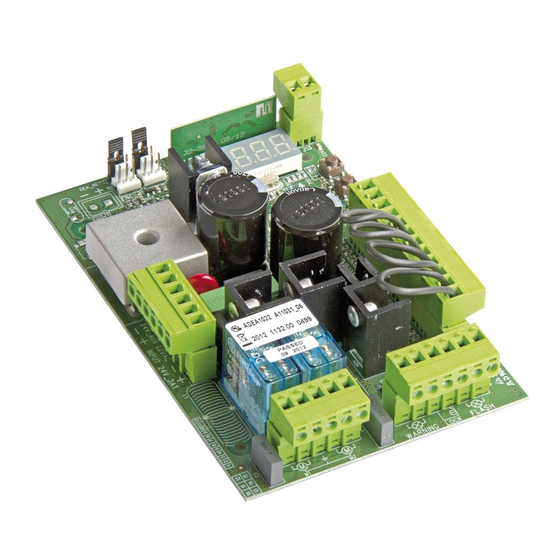
    2 DESCRIPTION DU PRODUIT NET24N est un armoire de commande universel pour automations DEA System à 1 ou 2 moteurs 24V avec ou sans encodeur. La caractéristique principale de cette platine est sa facilité de configuration des entrées et des sorties en fonction de chaque besoins assurant ainsi l’adaptabilité...
  • Page 73: Configuration

    CONFIGURATION DE L’ARMOIRE DE COMMANDE L’armoire de commande universelle Net24N peut être utilisée pour gérer les types ( ) de fermetures suivants motorisées par DEA System: portails battants et coulissants, portes de garage et barrières. Afin d’assurer une compatibilité maximale à chaque type ( ) de fermetures, la platine de commande prévoit une procédure...
  • Page 75 CONFIGURATION DES PORTAILS COULISSANTS BRANCHEMENTS ÉLÉCTRIQUES Exécutez les branchements éléctriques en suivant les indications de la table 1 et des schemas à page 74. Table 1 “branchement aux borniers” Sortie +24 V alimentation auxiliaire max 200mA Entrée alimentation 22V ~ du transformateur Entrée alimentation 24V de la batterie ou photovoltaïque accumulateur Green Energy (faire attention aux polarités).
  • Page 76 ROUGE BLEU...
  • Page 77 PROGRAMMATION STANDARD Alimentation Alimentez la carte, le display affiche en séquence les écrits “ ”, “ ”, “ ” suivis du symbole de portail fermé “----”. Dans le cas où la platine a déjà été programmée et le ré-allumage a été provoqué par une panne de courant, à la première impulsion de START, la procédure de réinitialisation sera effectuée (voir “rESP”...
  • Page 78 Sélection du sens de marche 1. Parcourez les paramètres avec les touches jusqu’à visualiser le paramètre P063; 2. Accédez au paramètre en appuyant sur la touche 3. En utilisant les touches , configurez: - d000=moteur en position standard (à la gauche de l’entrée);...
  • Page 79 7.2 Apprentissage 1. Parcourez les paramètres avec les touches jusqu’à visualiser sur le display P005; 2. Confirmez en appuyant sur la touche 3. Lorsque les symboles “ ” du display clignotent, appuyez sur la touche de l’émet- teur que vous voulez mémoriser; 4.
  • Page 81 CONFIGURATION DES PORTAILS BATTANTS BRANCHEMENTS ÉLÉCTRIQUES Exécutez les branchements éléctriques en suivant les indications de la table 1 et des schemas à page 80 Table 1 “branchement aux borniers” Sortie +24 V alimentation auxiliaire max 200mA Entrée alimentation 22V ~ du transformateur Entrée alimentation 24V de la batterie ou photovoltaïque accumulateur Green Energy (faire attention aux polarités).
  • Page 82 ROUGE BLEU BLEU ROUGE BLANCHE BLANCHE VERT VERT MARRON MARRON...
  • Page 83 PROGRAMMATION STANDARD Alimentation Alimentez la carte, le display affiche en séquence les écrits “ ”, “ ”, “ ” suivis du symbole de portail fermé “----”. Dans le cas où la platine a déjà été programmée et le ré-allumage a été provoqué par une panne de courant, à la première impulsion de START, la procédure de réinitialisation sera effectuée (voir “rESP”...
  • Page 84 Selectionnez le fonctionnement à 1 ou 2 moteurs 1. Parcourez les paramètres avec les touches jusqu’à visualiser la procédure P030; 2. Confirmez en appuyant sur la touche 3. En appuyant sur les touches , réglez: - d001=pour la fonction à 1 moteur; - d002=pour la fonction à...
  • Page 85 7.2 Apprentissage 1. Parcourez les paramètres avec les touches jusqu’à visualiser sur le display P005; 2. Confirmez en appuyant sur la touche 3. Lorsque les symboles “ ” du display clignotent, appuyez sur la touche de l’émet- teur que vous voulez mémoriser; 4.
  • Page 87 CONFIGURATION DES PORTES BASCULANTES BRANCHEMENTS ÉLÉCTRIQUES Exécutez les branchements éléctriques en suivant les indications de la Table 1 et des schemas à page 86. Table 1 “branchement aux borniers” Sortie +24 V alimentation auxiliaire max 200mA Entrée alimentation 22V ~ du transformateur Entrée alimentation 24V de la batterie ou photovoltaïque accumulateur Green Energy (faire attention aux polarités).
  • Page 88 BLEU ROUGE BLEU ROUGE BLEU BLEU ROUGE ROUGE MARRON MARRON VERT VERT BLANCHE BLANCHE...
  • Page 89 PROGRAMMATION STANDARD Alimentation Alimentez la carte, le display affiche en séquence les écrits “ ”, “ ”, “ ” suivis du symbole de portail fermé “----”. Dans le cas où la platine a déjà été programmée et le ré-allumage a été provoqué par une panne de courant, à la première impulsion de START, la procédure de réinitialisation sera effectuée (voir “rESP”...
  • Page 90 Apprentissage de la course des moteurs 1. Parcourez les paramètres avec les touches jusqu’à visualiser la procédure P003; 2. Confirmez en appuyant sur le bouton 3. L’écran affiche “ ” clignotant, appuyez sur le bouton 4. Relâchez le bouton lorsque “ ”...
  • Page 91 Modification des paramètres de fonctionnement Au cas où il serait nécessaire de modifier les paramètres de fonc- tionnement (par exemple force, vitesse etc….): 1. Parcourez avec les touches jusqu’à visualiser sur le display le paramètre désiré (par ex. P032); 2. Confirmez en appuyant sur la touche 3.
  • Page 93 CONFIGURATION DES BARRIÈRES BRANCHEMENTS ÉLÉCTRIQUES Exécutez les branchements éléctriques en suivant les indications de la Table 1 et des schemas à page 92. Table 1 “branchement aux borniers” Sortie +24 V alimentation auxiliaire max 200mA Entrée alimentation 22V ~ du transformateur Entrée alimentation 24V de la batterie ou photovoltaïque accumulateur Green Energy (faire attention aux polarités).
  • Page 94 ROUGE BLEU BLEU ROUGE ROUGE ROUGE BLEU BLEU MARRON MARRON VERT VERT BLANCHE BLANCHE...
  • Page 95 PROGRAMMATION STANDARD Alimentation Alimentez la carte, le display affiche en séquence les écrits “ ”, “ ”, “ ” suivis du symbole de portail fermé “----”. Dans le cas où la platine a déjà été programmée et le ré-allumage a été provoqué par une panne de courant, à la première impulsion de START, la procédure de réinitialisation sera effectuée (voir “rESP”...
  • Page 96 Selectionnez le fonctionnement à 1 ou 2 moteurs 1. Parcourez les paramètres avec les touches jusqu’à visualiser la procédure P030; 2. Confirmez en appuyant sur la touche 3. En appuyant sur les touches , réglez: - d001=pour la fonction à 1 moteur; - d002=pour la fonction à...
  • Page 97 8.2 Apprentissage 1. Parcourez les paramètres avec les touches jusqu’à visualiser sur le display P005; 2. Confirmez en appuyant sur la touche 3. Lorsque les symboles “ ” du display clignotent, appuyez sur la touche de l’émet- teur que vous voulez mémoriser; 4.
  • Page 99: Programmation Avancée

    5 PROGRAMMATION AVANCÉE Veuillez trouver ci-dessous certaines procédures de programmation concernant la gestion de la mémoire des émetteurs et la configu- ration avancée des entrées de commande. Effacement des émetteurs mémorisés 1.1 Effacement de tous les émetteurs 1. Parcourez les paramètres jusqu’à visualiser P004; 2.
  • Page 100 3.2 Déblocage accès à la programmation 1. Faites défiler les paramètres avec les touches jusqu’à ce que l’écran affiche P008; 2. Accédez au paramètre en appuyant sur la touche 3. L’affichage affiche alternativement pour indiquer que la platine est dans l’attente de la transmission du code de déblocage;...
  • Page 101 PROCÉDURES DE PROGRAMMATION PARAMÈTRES DE CONFIGURATION ENTRÉES...
  • Page 102 PARAMÈTRES CONFIGURATION PARAMÈTRES DE FONCTIONNEMENT MOTEURS...
  • Page 103 PARAMÈTRES DE FONCTIONNEMENT...
  • Page 104: Messages Affichés Sur Le Diplay

    Si la signalisation se répète, remplacez l’armoire de commande. 7 ESSAI D’INSTALLATION L’essai est une opération essentielle afin de vérifier la correcte installation du système. DEA System résume le fonctionnement correct de toute l’automatisation en 4 phases très simples: ● Assurez-vous que vous vous référez strictement tel que décrit au paragraphe 2 “RÉCAPITULATIF DES AVERTISSEMENTS”;...
  • Page 105 ATENCIÓN La evaluación equivocada de las fuerzas de impacto puede ser causa de graves daños en personas, animales o cosas. DEA System recuerda que el instalador tiene que comprobar que estas fuerzas de impacto, medidas según lo que indica la norma EN 12445, sean efectivamente inferiores a los límites previstos por la norma EN12453.
  • Page 106: Descripción Del Producto

    2 DESCRIPCIÓN DEL PRODUCTO NET24 es un cuadro de maniobras universal para automatizaciones DEA System para 1 o 2 motores con o sin encoder. La característica principal de ésta central es la simplicidad para configurar las entradas y salidas según las própias exigencias,garantizado de éste modo la adaptabilidad a todo tipo de motorizaciones.Bastará...
  • Page 107: Configuración

    CONFIGURACION DE LA CENTRAL La central de mando universal NET24N puede ser utilizada para la gestión de los siguientes tipos ( ) de cierre motorizado Dea System: cancela batiente, correderas,puerta basculante, barreras. Con el fin de garantizar la máxima adaptabilidad de cada tipo ( ) de cierre,la central prevee un procedimiento inicial, seguido al primer encendido, para una configuración óptima de las entradas, salidas y parámetros de funcionamiento (ver esquema...
  • Page 109 CONFIGURACION PUERTA CORREDERA CONEXIONES ELÉCTRICAS Realizar las conexiones eléctricas siguiendo las indicaciones de la “Tabla 1” y los esquemas de página 108. Tabla 1 “conexión a las borneras” Salida +24 V alimentación auxiliares máximo 200mA Entrada de la alimentación eléctrica 22 V ~ desde transformador Entrada de la alimentación 24 V desde batería o acumulador fotovoltaico Green Energy (prestar atención a la polaridad).
  • Page 110 ROJO AZUL...
  • Page 111 PROGRAMACIÓN ESTÁNDAR Alimentación Alimentar eléctricamente; en el display se visualizan en secuencia las inscripciones “ ”, “ ”, “ ” seguidas por el símbolo de puerta cerrada “----” En el caso que la central esté ya programada y el reencendido sea debido a una interrupción de la alimentación, al primer impulso de START, vendrá...
  • Page 112 Selección del sentido de la marcha 1. Correr los parámetros con los botones sta visualizar el el display P063; 2. Acceder al parámetro pulsando el botón 3. Accionando , introducir: - d000=motor en posición standar (a la izquierda del puente); - d001=motor en posición invertida (a la derecha del puente);...
  • Page 113 7.2 Aprendizaje 1. Correr los parámetros con las teclas hasta visualizar en el display el parámetro P005; 2. Acceder al parámetro apretando la tecla 3. Con la inscripción “ ” destellante apretar una tecla del control remoto que debe memo- rizarse;...
  • Page 115 CONFIGURACION CANCEL BATIENTE CONEXIONES ELÉCTRICAS Realizar las conexiones eléctricas siguiendo las indicaciones de la “Tabla 1” y los esquemas de página 114. Tabla 1 “conexión a las borneras” Salida +24 V alimentación auxiliares máximo 200mA Entrada de la alimentación eléctrica 22 V ~ desde transformador Entrada de la alimentación 24 V desde batería o acumulador fotovoltaico Green Energy (prestar atención a la polaridad).
  • Page 116 ROJO AZUL AZUL ROJO BLANCO BLANCO VERDE VERDE MARRÓN MARRÓN...
  • Page 117 PROGRAMACIÓN ESTÁNDAR Alimentación Alimentar eléctricamente; en el display se visualizan en secuencia las inscripciones “ ”, “ ”, “ ” seguidas por el símbolo de puerta cerrada “----” En el caso que la central esté ya programada y el reencendido sea debido a una interrupción de la alimentación, al primer impulso de START, vendrá...
  • Page 118 Selección de funcionamiento 1 o 2 motores 1. Correr los parámetros con las teclas hasta visualizar en el display el parámetro P030; 2. Acceder al parámetro apretando la tecla 3. Interviniendo en las teclas , configurar: - d001=para la función de motor simple; - d002=para la función de 2 motores;...
  • Page 119 7.2 Aprendizaje 1. Correr los parámetros con las teclas hasta visualizar en el display el parámetro P005; 2. Acceder al parámetro apretando la tecla 3. Con la inscripción “ ” destellante apretar una tecla del control remoto que debe memo- rizarse;...
  • Page 121 CONFIGURACION PUERTA BASCULANTE CONEXIONES ELÉCTRICAS Realizar las conexiones eléctricas siguiendo las indicaciones de la “Tabla 1” y los esquemas de página 120. Tabla 1 “conexión a las borneras” Salida +24 V alimentación auxiliares máximo 200mA Entrada de la alimentación eléctrica 22 V ~ desde transformador Entrada de la alimentación 24 V desde batería o acumulador fotovoltaico Green Energy (prestar atención a la polaridad).
  • Page 122 AZUL ROJO AZUL ROJO AZUL AZUL ROJO ROJO MARRÓN MARRÓN VERDE VERDE BLANCO BLANCO...
  • Page 123 PROGRAMACIÓN ESTÁNDAR Alimentación Alimentar eléctricamente; en el display se visualizan en secuencia las inscripciones “ ”, “ ”, “ ” seguidas por el símbolo de puerta cerrada “----” En el caso que la central esté ya programada y el reencendido sea debido a una interrupción de la alimentación, al primer impulso de START, vendrá...
  • Page 124 Aprendizaje de la carrera de los motores 1. Correr los parámetros con los botones hasta visualizar en el display P003; 2. Acceder al parámetro pulsando el botón 3. Al escrito “ ” intermitente, tener apretado el botón 4. Soltar el botón donde el escrito “...
  • Page 125 Modificación de los parámetros de funcionamiento En caso de que resulte necesario modificar los parámetros de fun- cionamiento (por ejemplo fuerza, velocidad, etc.): 1. Desplazarse con las teclas hasta visualizar en el di- splay el parámetro (es. P032); 2. Acceder al parámetro apretando la tecla 3.
  • Page 127 CONFIGURACION BARRERAS CONEXIONES ELÉCTRICAS Realizar las conexiones eléctricas siguiendo las indicaciones de la “Tabla 1” y los esquemas de página 126. Tabla 1 “conexión a las borneras” Salida +24 V alimentación auxiliares máximo 200mA Entrada de la alimentación eléctrica 22 V ~ desde transformador Entrada de la alimentación 24 V desde batería o acumulador fotovoltaico Green Energy (prestar atención a la polaridad).
  • Page 128 ROJO AZUL AZUL ROJO ROJO ROJO AZUL AZUL MARRÓN MARRÓN VERDE VERDE BLANCO BLANCO...
  • Page 129 PROGRAMACIÓN ESTÁNDAR Alimentación Alimentar eléctricamente; en el display se visualizan en secuencia las inscripciones “ ”, “ ”, “ ” seguidas por el símbolo de puerta cerrada “----” En el caso que la central esté ya programada y el reencendido sea debido a una interrupción de la alimentación, al primer impulso de START, vendrá...
  • Page 130 Selección de funcionamiento 1 o 2 motores 1. Correr los parámetros con las teclas hasta visualizar en el display el parámetro P030; 2. Acceder al parámetro apretando la tecla 3. Interviniendo en las teclas , configurar: - d001=para la función de motor simple; - d002=para la función de 2 motores;...
  • Page 131 8.2 Aprendizaje 1. Correr los parámetros con las teclas hasta visualizar en el display el parámetro P005; 2. Acceder al parámetro apretando la tecla 3. Con la inscripción “ ” destellante apretar una tecla del control remoto que debe memo- rizarse;...
  • Page 133: Programación Avanzada

    5 PROGRAMACIÓN AVANZADA A continuación se añaden algunos procedimientos de programación relativos a la gestión de la memoria de los controles remotos y a la configuración avanzada de las entradas de mando. Cancelación de los controles remotos memorizados 1.1 Cancelación de todos los controles remotos 1.
  • Page 134 3.2 Desbloqueo acceso a la programación 1. Posicionar con el botón el P008 en el di- splay; 2. Acceder al parámetro apretando el botón 3. En el display se visualiza de modo alterno el escri- que indica que la central está esperando la transmisión del código de bloqueo;...
  • Page 135 PROCEDURE DI PROGRAMMAZIONE PARÁMETROS DE CONFIGURACIÓN DE LAS ENTRADAS...
  • Page 136 PARÁMETROS CONFIGURACIÓN PARÁMETROS DE FUNCIONAMIENTO MOTORES...
  • Page 137 PARÁMETROS DE FUNCIONAMIENTO...
  • Page 138: Mensaje Visualizados En El Display

    - Si la señalización se repite, sustituir la central de maniobra. 7 ENSAYO DE LA INSTALACIÓN El ensayo es una operación esencial para comprobar la instalación correcta del sistema. DEA System desea resumir el ensayo cor- recto de toda la automatización en 4 simples fases: ●...
  • Page 139 ATENÇÃO A DEA System recorda a todos os utilizadores que a escolha e instalação de todos os materiais e dispositivos que com- põem o sistema de automação completo, devem cumprir com as Directivas Europeias 2006/42/CE (Directiva Máquinas), 2004/108/ CE (compatibilidade electromagnética), 2006/95/CE (equipamentos eléctricos de baixa tensão).
  • Page 140: Descrição Do Produto

    2 DESCRIÇÃO DO PRODUTO NET24N é uma central de comando universal para automações DEA System de 1 ou 2 motores de 24V com ou sem encoder. A característica principal desta central de comando é a sua facilidade de configuração das entradas e saídas de acordo com as necessidades, garantindo assim a capacidade de adaptação a qualquer tipo de automação.
  • Page 141: Portões De Correr

    CONFIGURAÇÃO DA CENTRAL DE COMANDO A central de comando Net24N pode ser utilizada para o controlo dos seguintes tipos ( ) de fecho motorizados pela DEA System: Portas de batente e de correr, portas basculantes e barreiras. A fim de garantir a adaptabilidade máxima para cada tipo ( ) de fecho, a central de comando fornece um procedimento inicial, realizado apenas no primeiro ciclo, para a configuração ideal das entradas, saídas e parâmetros (ver o diagrama...
  • Page 143 CONFIGURAÇÃO DE PORTÕES DE CORRER LIGAÇÕES ELÉCTRICAS Execute a cablagem seguindo as instruções da “Tabela 1” e os diagramas na página 142. Tabela 1 “Ligações aos terminais da central” Saída de +24 V para dispositivos auxiliares 200mA Entrada para o transformador de 22 V ~ Entrada para ligação de baterias de 24 V ou acumulador fotovoltaico Green Energy (Respeitar a polaridade).
  • Page 144 VERMELHO AZUL...
  • Page 145 PROGRAMAÇÃO PADRÃO Alimentação Alimente a central, o display mostra os seguintes símbolos “ ”, “ ”, “ ” e depois “----”. Se a central de comando já foi programada e houver uma falha de corrente ou esta for desligada – quando voltar a ser alimentada e for dado um comando de START, o processo de redefinição da posição é...
  • Page 146 Selecção da direcção do movimento 1. Percorra os parâmetros com as teclas até visualizar P063; 2. Aceda ao parâmetro pressionando a tecla 3. Através das teclas , defina: - d000=motor na posição padrão (do lado esquer- do); - d001=motor na posição invertida (do lado direi- to);...
  • Page 147 7.2 Aprendizagem 1. Percorra os parâmetros com os símbolos até aparecer no display P005; 2. Confirme pressionando a tecla 3. Quando o símbolo “ ” piscar, pressio- ne qualquer tecla do emissor que queira memorizar; 4. O display mostra o número do emissor me- morizado e depois pisca novamente o sím- bolo “...
  • Page 149 CONFIGURAÇÃO DE PORTÕES DE BATENTE LIGAÇÕES ELÉCTRICAS Execute a cablagem seguindo as instruções da “Tabela 1” e os diagramas na página 148. Tabela 1 “Ligações aos terminais da central” Saída de +24 V para dispositivos auxiliares 200mA Entrada para o transformador de 22 V ~ Entrada para ligação de baterias de 24 V ou acumulador fotovoltaico Green Energy (Respeitar a polaridade).
  • Page 150 VERMELHO AZUL AZUL VERMELHO BRANCO BRANCO VERDE VERDE CASTANHO CASTANHO...
  • Page 151 PROGRAMAÇÃO PADRÃO Alimentação Alimente a central, o display mostra os seguintes símbolos “ ”, “ ”, “ ” e depois “----”. Se a central de comando já foi programada e houver uma falha de corrente ou esta for desligada – quando voltar a ser alimentada e for dado um comando de START, o processo de redefinição da posição é...
  • Page 152 Selecção de funcionamento a 1 ou 2 motores 1. Percorra os parâmetros com as teclas até visualizar P030; 2. Aceda ao parâmetro pressionando a tecla 3. Através das teclas , defina: - d001=para funcionamento a 1 motor; - d002=para funcionamento a 2 motores; 4.
  • Page 153 Ajuste dos parâmetros de funcionamento Se necessitar de modificar os parâmetros de funcionamento (força, velocidade, etc.): 1. Percorra os parâmetros até aparecer (por ex. P032); 2. Confirme pressionando a tecla 3. Pressionando as teclas , ajuste o valor desejado; 4. Confirme pressionando a tecla (o display mostra o de novo o parâmetro seleccionado).
  • Page 155 CONFIGURAÇÃO DE PORTÕES BASCULANTES LIGAÇÕES ELÉCTRICAS Execute a cablagem seguindo as instruções da “Tabela 1” e os diagramas na página 154. Tabela 1 “Ligações aos terminais da central” Saída de +24 V para dispositivos auxiliares 200mA Entrada para o transformador de 22 V ~ Entrada para ligação de baterias de 24 V ou acumulador fotovoltaico Green Energy (Respeitar a polaridade).
  • Page 156 AZUL VERMELHO AZUL VERMELHO AZUL AZUL VERMELHO VERMELHO CASTANHO CASTANHO VERDE VERDE BRANCO BRANCO...
  • Page 157 PROGRAMAÇÃO PADRÃO Alimentação Alimente a central, o display mostra os seguintes símbolos “ ”, “ ”, “ ” e depois “----”. Se a central de comando já foi programada e houver uma falha de corrente ou esta for desligada – quando voltar a ser alimentada e for dado um comando de START, o processo de redefinição da posição é...
  • Page 158 Aprendizagem do curso do motor 1. Percorra os parâmetros com as teclas até visualizar P003; 2. Aceda ao parâmetro pressionando a tecla 3. Quando “ ” piscar, continue pressionando a tecla 4. Liberte a tecla quando “ ” deixar de piscar; o procedimento de aprendizagem inicia; 5.
  • Page 159 Ajuste dos parâmetros de funcionamento Se necessitar de modificar os parâmetros de funcionamento (força, velocidade, etc.): 1. Percorra os parâmetros até aparecer (por ex. P032); 2. Confirme pressionando a tecla 3. Pressionando as teclas , ajuste o valor desejado; 4. Confirme pressionando a tecla (o display mostra o de novo o parâmetro seleccionado).
  • Page 161 CONFIGURAÇÃO DE BARREIRAS LIGAÇÕES ELÉCTRICAS Execute a cablagem seguindo as instruções da “Tabela 1” e os diagramas na página 160. Tabela 1 “Ligações aos terminais da central” Saída de +24 V para dispositivos auxiliares 200mA Entrada para o transformador de 22 V ~ Entrada para ligação de baterias de 24 V ou acumulador fotovoltaico Green Energy (Respeitar a polaridade).
  • Page 162 VERMELHO AZUL AZUL VERMELHO VERMELHO VERMELHO AZUL AZUL CASTANHO CASTANHO VERDE VERDE BRANCO BRANCO...
  • Page 163 PROGRAMAÇÃO PADRÃO Alimentação Alimente a central, o display mostra os seguintes símbolos “ ”, “ ”, “ ” e depois “----”. Se a central de comando já foi programada e houver uma falha de corrente ou esta for desligada – quando voltar a ser alimentada e for dado um comando de START, o processo de redefinição da posição é...
  • Page 164 Selecção de funcionamento a 1 ou 2 motores 1. Percorra os parâmetros com as teclas até visualizar P030; 2. Aceda ao parâmetro pressionando a tecla 3. Através das teclas , defina: - d001=para funcionamento a 1 motor; - d002=para funcionamento a 2 motores; 4.
  • Page 165 8.2 Aprendizagem 1. Percorra os parâmetros com os símbolos até aparecer no display P005; 2. Confirme pressionando a tecla 3. Quando o símbolo “ ” piscar, pressio- ne qualquer tecla do emissor que queira memorizar; 4. O display mostra o número do emissor me- morizado e depois pisca novamente o sím- bolo “...
  • Page 167: Programação Avançada

    5 PROGRAMAÇÃO AVANÇADA Aqui estão alguns procedimentos de programação adicionais relativos à gestão da memória de emissores e configuração avançada das entradas de controlo. Apagar os emissores memorizados 1.1 Apagar todos os comandos 1. Percorra os parâmetros com os símbolos até...
  • Page 168 3.2 Desbloqueio de acesso à programação 1. Percorrer os parâmetros através dos botões até o display mostrar P008; 2. Aceda ao parâmetro pressionando o botão 3. O display mostra alternadamente a escrita para indicar que a central de co- mando está à espera da transmissão do código de desbloqueio;...
  • Page 169 PROCEDIMENTOS DE PROGRAMAÇÃO CONFIGURAÇÃO DOS PARÂMETROS DAS ENTRADAS...
  • Page 170 CONFIGURAÇÃO DOS PARÂMETROS DE PARÂMETROS DE FUNCIONAMENTO FUNCIONAMENTO...
  • Page 171 PARÂMETROS DE FUNCIONAMENTO...
  • Page 172: Teste Da Instalação

    - Se esse erro aparecer novamente, substituir a central de comando. 7 TESTE DA INSTALAÇÃO A realização de testes é essencial a fim de verificar a correcta instalação do sistema. A DEA System resume o teste adequado de toda a automatização em 4 passos fáceis: ●...
  • Page 173 UWAGA DEA System przypomina, ze wybór, wykorzystanie i montaz wszystkich urzadzen i akcesoriów, stanowiacych pelny system auto- matyzacji powinien odbywac sie w zgodnosci z Dyrektywami Europejskimi: 2006/42/CE (Dyrektywa o Maszynach), 2004/108/CE (dotyc- zaca kompatybilnosci elektromagnetycznej), 2006/95/CE (dotyczaca urzadzen elektrycznych zasilanych niskim napieciem).
  • Page 174 2 OPIS PRODUKTU NET24N jest uniwersalną centralą sterującą do automatyki DEA System z jednym lub dwoma silnikami 24V, posiadającą lub nie encoder. Główną cechą charakterystyczna tej centrali jest łatwość konfi guracji jej wejść i wyjść - zależnie od zapotrzebowania, gwarantując w ten spo- sób niezawodność...
  • Page 175 KONFIGURACJA CENTRALI Uniwersalną centralę sterującą Net24N można zastosować do następujących rodzajów zautomatyzowanych systemów zamykania DEA System dla: bram skrzydłowych, przesuwnych, bram garażowych segmentowych oraz zapór. W celu zagwarantowania maksymalnego przystosowania do każdego typu zamykania, centrala przewiduje procedurę początkową, do wy- konania przy pierwszym uruchomieniu, mającą...
  • Page 177 KONFIGURACJA BRAMY PRZESUWANEJ PODŁĄCZENIA ELEKTRYCZNE wykonaj okablowanie stosując się do informacji zawartej w tabeli nr.1 i schematów ze str. 176 Tabela nr. 1 “podłączenie zacisków” +24 V zasilanie akcesoriów max 200mA Wejście zasilania 22 V ~ Wejście zasilania 24 V z baterii lub fotowoltaicznej akumulator Green Energy (uwaga na polaryzację).
  • Page 178 CZERWONY GRANATOWY...
  • Page 179 PROGRAMOWANIE STANDARDOWE Zasilanie Podłączyć zasilanie, na wyświetlaczu pojawią się kolejno napisy “ ”, “ ”, “ ” a następnie “- - - -” W przypadku gdy centrala sterująca już została zaprogramowana i ponowne włączenie jest spowodowane brakiem zasilania, przy pierwszym impulsie START, zostanie wykonana procedura resetu ustawień...
  • Page 180 Wybór kierunku ruchu 1. Naciśnij przycisk aż do momentu pojawienia się na wyświetlaczu P063; 2. Naciskając przycisk wejść w parametr; 3. Naciskając przyciski , ustawić: - d000=silnik w pozycji standardowej (na lewo od przejścia); - d001=silnik w pozycji odwróconej (na prawo od przejścia);...
  • Page 181 7.2 Uczenie 1. Naciskaj przycisk do momentu pojawie- nia się na wyświetlaczu P005; 2. Zatwierdź przyciskiem 3. Po pojawieniu się migającego symbolu “ ” naciśnij dowolny przycisk nadajnika do zaprogra- mowania; 4. Na wyświetlaczu pojawi się skrót wkodowane- go nadajnika a następnie pojawi się migający symbol “...
  • Page 183 KONFIGURACJA BRAM SKRZYDŁOWYCH PODŁĄCZENIA ELEKTRYCZNE wykonaj okablowanie stosując się do informacji zawartej w tabeli nr.1 i schematów ze str. 182 Tabela nr. 1 “podłączenie zacisków” +24 V zasilanie akcesoriów max 200mA Wejście zasilania 22 V ~ Wejście zasilania 24 V z baterii lub fotowoltaicznej akumulator Green Energy (uwaga na polaryzację).
  • Page 184 CZERWONY GRANATOWY GRANATOWY CZERWONY BIAŁY BIAŁY ZIELEŃ ZIELEŃ BRĄZ BRĄZ...
  • Page 185 STANDARDOWE PROGRAMOWANIE Zasilanie Podłączyć zasilanie, na wyświetlaczu pojawią się kolejno napisy “ ”, “ ”, “ ” a następnie “- - - -” W przypadku gdy centrala sterująca już została zaprogramowana i ponowne włączenie jest spowodowane brakiem zasilania, przy pierwszym impulsie START, zostanie wykonana procedura resetu ustawień...
  • Page 186 Wybór działania 1 lub 2 siłowników 1. Naciskaj przycisk do momentu pojawienia się na wyświetlaczu P030; 2. Zatwierdź przyciskiem 3. Naciskając przycisk , ustaw: - d001=dla 1 siłownika; - d002=dla 2 siłowników; 4. Zatwierdź przyciskiem (na wyświetlaczu pojawi się ponownie P030).
  • Page 187 7.2 Uczenie 1. Naciskaj przycisk do momentu pojawie- nia się na wyświetlaczu P005; 2. Zatwierdź przyciskiem 3. Po pojawieniu się migającego symbolu “ ” naciśnij dowolny przycisk nadajnika do zaprogra- mowania; 4. Na wyświetlaczu pojawi się skrót wkodowane- go nadajnika a następnie pojawi się migający symbol “...
  • Page 189 KONFIGURACJA BRAM GARAZOWYCH PODŁĄCZENIA ELEKTRYCZNE wykonaj okablowanie stosując się do informacji zawartej w tabeli nr.1 i schematów ze str. 188 Tabela nr. 1 “podłączenie zacisków” +24 V zasilanie akcesoriów max 200mA Wejście zasilania 22 V ~ Wejście zasilania 24 V z baterii lub fotowoltaicznej akumulator Green Energy (uwaga na polaryzację).
  • Page 190 GRANATOWY CZERWONY GRANATOWY CZERWONY GRANATOWY GRANATOWY CZERWONY CZERWONY BRĄZ BRĄZ ZIELEŃ ZIELEŃ BIAŁY BIAŁY...
  • Page 191 STANDARDOWE PROGRAMOWANIE Zasilanie Podłączyć zasilanie, na wyświetlaczu pojawią się kolejno napisy “ ”, “ ”, “ ” a następnie “- - - -” W przypadku gdy centrala sterująca już została zaprogramowana i ponowne włączenie jest spowodowane brakiem zasilania, przy pierwszym impulsie START, zostanie wykonana procedura resetu ustawień...
  • Page 192 Programowanie drogi poruszania się siłowników 1. Naciskaj przycisk do momentu pojawienia się na wyświetlaczu P003; 2. Zatwierdź przyciskiem 3. Po pojawieniu się migającego symbolu “ ” przyciśnij na kilka sekund; 4. Zwolnij przycisk kiedy symbol przestanie migać, procedura uczenia rozpoczęta; 5.
  • Page 193 Zmiana pozostałych parametrów W przypadku jeśli chcesz zmodyfi kować parametry działania (np. siła, szybkość itd..): 1. Naciskaj przycisk do momentu pojawienia się na wyświetlaczu żądanego parametru (np. P032); 2. Zatwierdź przyciskiem 3. Przez naciskanie , ustaw parametr na żądaną wartość; 4.
  • Page 195 KONFIGURACJA ZAPORA PODŁĄCZENIA ELEKTRYCZNE wykonaj okablowanie stosując się do informacji zawartej w tabeli nr.1 i schematów ze str. 194 Tabela nr. 1 “podłączenie zacisków” +24 V zasilanie akcesoriów max 200mA Wejście zasilania 22 V ~ Wejście zasilania 24 V z baterii lub fotowoltaicznej akumulator Green Energy (uwaga na polaryzację). Wyjście siłownika nr.
  • Page 196 CZERWONY GRANATOWY GRANATOWY CZERWONY CZERWONY CZERWONY GRANATOWY GRANATOWY BRĄZ BRĄZ ZIELEŃ ZIELEŃ BIAŁY BIAŁY...
  • Page 197 STANDARDOWE PROGRAMOWANIE Zasilanie Podłączyć zasilanie, na wyświetlaczu pojawią się kolejno napisy “ ”, “ ”, “ ” a następnie “- - - -” W przypadku gdy centrala sterująca już została zaprogramowana i ponowne włączenie jest spowodowane brakiem zasilania, przy pierwszym impulsie START, zostanie wykonana procedura resetu ustawień...
  • Page 198 Wybór działania 1 lub 2 siłowników 1. Naciskaj przycisk do momentu pojawienia się na wyświetlaczu P030; 2. Zatwierdź przyciskiem 3. Naciskając przycisk , ustaw: - d001=dla 1 siłownika; - d002=dla 2 siłowników; 4. Zatwierdź przyciskiem (na wyświetlaczu pojawi się ponownie P030).
  • Page 199 8.2 Uczenie 1. Naciskaj przycisk do momentu pojawie- nia się na wyświetlaczu P005; 2. Zatwierdź przyciskiem 3. Po pojawieniu się migającego symbolu “ ” naciśnij dowolny przycisk nadajnika do zaprogra- mowania; 4. Na wyświetlaczu pojawi się skrót wkodowane- go nadajnika a następnie pojawi się migający symbol “...
  • Page 201 5 PROGRAMOWANIE ZAAWANSOWANE Poniżej zostały dodane niektóre procedury programowania zarządzania pamięcią odbiornika i zaawansowana konfi guracja wejść. Usuwanie zaprogramowanych nadajników 1.1 Kasowanie wszystkich nadajników 1. Naciskaj przycisk do momentu pojawienia się na wyświetlaczu P004; 2. Zatwierdź przyciskiem 3. Po pojawieniu się migającego symbolu “ ”...
  • Page 202 3.2 Odblokowanie dostępu do programowania 1. Nacisnąć przycisk parametrów do momentu pojawienia się na wyświetlaczu P008; 2. Wejść do parametru naciskając przycisk 3. Wyświetlacz pokazuje napisy w spo- sób przemienny, co wskazuje na to ze centrala oc- zekuje na transmisję kodu odblokowania; 4.
  • Page 203 PARAMETRY PROGRAMOWANIA PARAMETRY KONFIGURACJI WEJŚĆ...
  • Page 204 PARAMETRY KONFIGURACYJNE PARAMETR Y DZIAŁANIA SIŁOWNIKÓW SIŁOWNIKI...
  • Page 205 PARAMETR Y DZIAŁANIA...
  • Page 206 - Jeśli błąd się będzie powtarzał, wymienić centralę sterującą. 7 TESTOWANIE INSTALACJI Testowanie jest operacją niezbędną do sprawdzenia działania systemu. DEA System zbiorczo pokazuje poprawność testowania w 4 prost- ych krokach: ● Upewnij się , że wszystko jest zgodne z zaleceniami paragrafu 2 “Ostrzeżenia dotyczące potencjalnych niebezpieczeństw”;...
  • Page 208 W celu wsparcia ochrony środowiska, niniejszą instrukcję zrealizowaliśmy wykorzystując papier ekologiczny pochodzący z recyklingu i posiadający certy•ikat Ecolabel. DEA SYSTEM S.p.A. - Via Della Tecnica, 6 - ITALY - 36013 PIOVENE ROCCHETTE (VI) tel. +39 0445 550789 - fax +39 0445 550265 - Internet http:\\www.deasystem.com - e-mail: deasystem@deasystem.com...

Table des Matières