Table des Matières
Publicité
Les langues disponibles
Les langues disponibles
Liens rapides
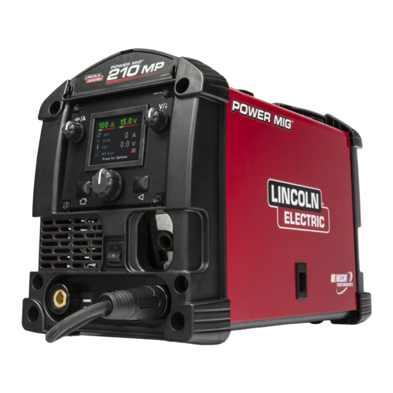
Operator's Manual
POWER MIG
Register your machine:
www.lincolnelectric.com/register
Authorized Service and Distributor Locator:
www.lincolnelectric.com/locator
Save for future reference
Date Purchased
Code: (ex: 10859)
Serial: (ex: U1060512345)
IMT10164-A
| Issue D ate Aug-19
© Lincoln Global, Inc. All Rights Reserved.
210 MP
®
For use with machines having Code Numbers:
12185, 12630
Publicité
Table des Matières

Manuels Connexes pour Lincoln Electric POWER MIG 210 MP 12185

Sommaire des Matières pour Lincoln Electric POWER MIG 210 MP 12185
- Page 1 Operator’s Manual POWER MIG 210 MP ® For use with machines having Code Numbers: 12185, 12630 Register your machine: www.lincolnelectric.com/register Authorized Service and Distributor Locator: www.lincolnelectric.com/locator Save for future reference Date Purchased Code: (ex: 10859) Serial: (ex: U1060512345) IMT10164-A | Issue D ate Aug-19 ©...
-
Page 2: Special Situations
THANK YOU FOR SELECTING A QUALITY PRODUCT BY KEEP YOUR HEAD OUT OF THE FUMES. DON’T get too close to the arc. LINCOLN ELEC TRIC. Use corrective lenses if necessary to stay a reasonable distance away from the arc. READ and obey the Safety Data PLEASE EXAMINE CARTON AND EQUIPMENT FOR Sheet (SDS) and the warning label DAMAGE IMMEDIATELY... -
Page 3: California Proposition 65 Warnings
W117.2-1974. A Free copy of “Arc Welding Safety” booklet E205 is available from the Lincoln Electric Company, 2.d. All welders should use the following procedures in order to 22801 St. Clair Avenue, Cleveland, Ohio 44117-1199. - Page 4 SAFETY ELECTRIC SHOCK ARC RAYS CAN BURN. CAN KILL. 3.a. The electrode and work (or ground) circuits are 4.a. Use a shield with the proper filter and cover plates to protect your electrically “hot” when the welder is on. Do eyes from sparks and the rays of the arc when welding or not touch these “hot”...
- Page 5 SAFETY WELDING AND CUTTING CYLINDER MAY EXPLODE IF SPARKS CAN CAUSE DAMAGED. FIRE OR EXPLOSION. 7.a. Use only compressed gas cylinders containing the correct shielding gas for the process used 6.a. Remove fire hazards from the welding area. If and properly operating regulators designed for this is not possible, cover them to prevent the welding sparks the gas and pressure used.
- Page 6 POWER MIG ® 210 MP TABLE OF CONTENTS...
-
Page 7: Product Summary
POWER MIG ® 210 MP PRODUCT DESCRIPTION PRODUCT DESCRIPTION PRODUCT SUMMARY The Power MIG™ 210 MP is a multi-process CC/CV DC inverter rated for 200 amps, 24 volts at a 25% duty cycle. The Power MIG™ units are intended for fabrication, maintenance, home, and autobody shops. - Page 8 PRODUCT DESCRIPTION RECOMMENDED PROCESSES AND EQUIPMENT COMMON EQUIPMENT PACKAGES RECOMMENDED PROCESSES The Power MIG ® 210 MP is recommended for GMAW, FCAW, GTAW, and SMAW processes. The machine can support 4 inch and 8 inch BASIC PACKAGE: spools of wire for GMAW and FCAW welding. The machine is intended CODE 12630 DETAILS for the following wire diameters and composition;...
- Page 9 POWER MIG ® 210 MP DESIGN DESIGN SPECIFICATIONS POWER SOURCES - INPUT VOLTAGE AND CURRENT WELDING PROCESSES PROCESS ELECTRODE DIAMETER RANGE OUTPUT RANGE WIRE FEED DUTY CYCLE INPUT VOLTAGE INPUT AMPERES IDLE AMPS (OUTPUT) (AMPERES) SPEED RANGE .55A GMAW .025-.035” 20-220 50-500 IPM (200A / 24V)
-
Page 10: Regulatory Requirements
POWER MIG ® 210 MP DESIGN REGULATORY REQUIREMENTS MODEL MARKET CONFORMITY STANDARD MARK K3963-1 US AND cCSA IEC 60974-1 CANADA IEC 60974-5 DESIGN FEATURES • 3.5-Inch Color TFT LCD Display –with 320x240 resolution facilitates adjusting weld processes and parameters. • Efficient Inverter power topology- reduces power consumption and reduces the mass of the unit when compared with traditional SCR based machines. - Page 11 POWER MIG ® 210 MP DESIGN CASE FRONT CONTROLS FIGURE A.1 CASE FRONT CONTROL DESCRIPTIONS 8. Gun Connection – Permits attachment of a MIG welding gun. 1. Storage Compartment – Provides storage for small items such as Ensure the gun is fully seated into the brass receptacle. tips and drive rolls.
-
Page 13: Location And Mounting
POWER MIG ® 210 MP INSTALLATION INSTALLATION 3. The Power MIG 210 MP is shipped with (two) six-foot power cords. 4. Using the instructions in Figure B.2, have a qualified electrician connect a receptacle (Customer Supplied) or cable to the input power lines and the system ground per the U.S. -
Page 14: Gun And Cable Installation
POWER MIG ® 210 MP INSTALLATION CONNECTION DIAGRAM(S), SYSTEM DO NOT ATTACH THE REGULATOR IF OIL, GREASE OR DAMAGE IS PRESENT! Inform your gas supplier of this condition. Oil or grease in GUN AND CABLE INSTALLATION the presence of high pressure oxygen is explosive. The Magnum PRO 175L gun and cable provided with the Power MIG 210MP is factory installed with a liner for .025-.035"... -
Page 15: Output Polarity Connections
POWER MIG ® 210 MP INSTALLATION PROCEDURE FOR CHANGING DRIVE AND IDLE ROLL SETS ELECTRODE AND WORK CONNECTIONS 1. Turn off the power source. OUTPUT POLARITY CONNECTIONS 2. Release the pressure on the idle roll by swinging the adjustable The Power MIG 210MP features a short lead protruding from the front pressure arm down toward the back of the machine. - Page 16 POWER MIG ® 210 MP OPERATION OPERATION GRAPHIC SYMBOLS USED IN THIS MANUAL OR BY THIS MACHINE POWER-UP SEQUENCE 1. Check that the electrode polarity is correct for the process being 3. Press the trigger to feed the wire electrode through the gun and used, then turn the power switch ON.
- Page 17 POWER MIG ® 210 MP OPERATION The following images help indicate the machine setup process. Figure C.1 Figure C.2 Verify polarity configuration and gas mix. Then press knob to continue.
- Page 18 POWER MIG ® 210 MP OPERATION Figure C.3 Figure C.4...
- Page 19 POWER MIG ® 210 MP OPERATION Figure C.5 Figure C.6...
-
Page 20: Duty Cycle
POWER MIG ® 210 MP OPERATION Figure C.7 DUTY CYCLE Figure C.8 RATED OUTPUT For additional output ratings reference the S30185 rating plate. The duty cycle is the “on” time (based on a 10 minute interval) the user can weld with the machine at a specific output without causing a thermal trip. Example: 30% duty cycle means welding at the specified output for If the duty cycle of the machine is exceeded, then the machine will 3 constant minutes and needing 7 minutes of “off”... -
Page 21: Options And Settings
PRODUCT MODEL OPERATION OPTIONS AND SETTINGS MIG OPTIONS The user interface software settings can be reset to the original factory settings. The inductance option permits adjusting the arc performance, this option can be used to help with starting and the weld bead profile. - Page 22 POWER MIG ® 210 MP OPERATION...
-
Page 23: Drive Roll Kits
POWER MIG ® 210 MP ACCESSORIES GENERAL OPTIONS / ACCESSORIES DRIVE ROLL KITS WIRE SIZE DRIVE ROLL KIT .023" - .030" KP2529-1 (0.6 - 0.8 MM) SOLID .035" (0.9 MM) KP2529-2 CORED .030- .045" (0.9 MM) KP2529-3 KITS AND OPTIONS K520 UTILITY CART (150 CU FT. -
Page 24: Periodic Maintenance
POWER MIG ® 210 MP MAINTENANCE ROUTINE MAINTENANCE CAUTION PERIODIC MAINTENANCE WARNING LINER REMOVAL, INSTALLATION AND TRIMMING INSTRUCTIONS FOR MAGNUM PRO 175L NOTE: The variation in cable lengths prevents interchanging of liners Before carrying out service, maintenance and/or between guns. Once a liner has been cut for a particular gun, it repair jobs, fully disconnect power to the machine. - Page 25 HOW TO USE TROUBLESHOOTING GUIDE WARNING Service and Repair should only be performed by Lincoln Electric Factory Trained Personnel. Unauthorized repairs performed on this equipment may result in danger to the technician and machine operator and will invalidate your factory warranty.
- Page 26 POWER MIG ® 210 MP TROUBLE SHOOTING Observe all Safety Guidelines detailed throughout this manual PROBLEMS POSSIBLE RECOMMENDED (SYMPTOMS) CAUSE COURSE OF ACTION Major physical or electrical damage is “Do not Plug in machine or turn it on.” evident. Contact your local Authorized Field Service Facility.
- Page 27 POWER MIG ® 210 MP TROUBLE SHOOTING Observe all Safety Guidelines detailed throughout this manual PROBLEMS POSSIBLE RECOMMENDED (SYMPTOMS) CAUSE COURSE OF ACTION Arc is unstable - Poor starting. 1. Check for correct input voltage to machine. 2. Check for proper electrode polarity for process.
- Page 28 POWER MIG ® 210 MP DIAGRAMS...
- Page 29 POWER MIG ® 210 MP DIAGRAMS...
- Page 30 Manual del operador POWER MIG 210 MP ® Para utilizar con máquinas que tengan los siguientes Números de código: 12185, 12630 Registre su máquina: www.lincolnelectric.com/register Localizador de distribuidores y servicios autorizados: www.lincolnelectric.com/locator Guarde estos datos como referencia para el futuro Fecha de la compra Código: (ej.: 10859) Serie: (ej.: U1060512345)
- Page 31 GRACIAS POR ADQUIRIR UN NO SE ACERQUE AL HUMO. PRODUCTO DE PRIMERA NO se acerque demasiado al arco. CALIDAD DE LINCOLN Si es necesario, utilice lentillas para ELEC TRIC. poder trabajar a una distancia razonable del arco. LEA y ponga en práctica el contenido de las hojas de datos sobre seguridad y el de las COMPRUEBE QUE LA CAJA Y EL EQUIPO ESTÉN...
- Page 32 E205, “Seguridad en los procesos de soldadura por 2.c. La exposición a los campos EM de la soldadura podría tener arco”, en Lincoln Electric Company, situada en 22801 St. Clair otros efectos sobre la salud que aún se desconocen.
- Page 33 SEGURID D UNA DESCARGA LAS RADIACIONES ELÉCTRICA LE PUEDE DEL ARCO QUEMAN. MATAR. 4.a. Utilice un protector con el filtro y las cubiertas debidos para protegerse los ojos de las chispas 3.a. Los circuitos auxiliar (tierra) y del electrodo y de las radiaciones del arco cuando esté soldando están vivos desde el punto de vista u observando una soldadura por arco.
- Page 34 SEGURID D LAS CHISPAS SI SE DAÑAN, LAS BOMBONAS DERIVADAS DE PUEDEN EXPLOTAR. CORTES 7.a. Utilice únicamente bombonas de gas Y SOLDADURAS comprimido que contengan los gases de PUEDEN PROVOCAR protección adecuados para el proceso en cuestión, así como reguladores diseñados INCENDIOS O EXPLOSIONES.
- Page 35 POWER MIG ® 210 MP ÍNDICE...
-
Page 36: Resumen Del Producto
POWER MIG ® 210 MP DESCRIPCIÓN DEL PRODUCTO DESCRIPCIÓN DEL PRODUCTO RESUMEN DEL PRODUCTO ® La Power MIG 210 MP es una unidad de CD multiproceso de corriente constante/tensión constante con inversor, especificada para 200 A/24 V con un ciclo de trabajo de 25%. Las unidades Power MIG™... - Page 37 DESCRIPCIÓN DEL PRODUCTO PROCESOS Y EQUIPOS RECOMENDADOS PROCESOS RECOMENDADOS ® La Power MIG 210 MP se recomienda para los procesos GMAW, CONJUNTOS DE EQUIPO COMUNES FCAW, GTAW y SMAW. La máquina admite carretes de alambre de 4 pulgadas y de 8 pulgadas para soldadura GMAW y FCAW. La máquina está...
- Page 38 POWER MIG 210 MP DISEÑO ® DISEÑO ESPECIFICACIONES PROCESOS DE SOLDADURA FUENTES DE ENERGÍA - TENSIÓN Y CORRIENTE DE ENTRADA CICLO DE TRABAJO TENSIÓN DE CORRIENTE DE CORRIENTE DE PROCESO RANGO DE DIÁMETROS DE RANGO DE RANGO DE VELOC. (SALIDA) ENTRADA (V) ENTRADA MÁXIMOS REPOSO...
-
Page 39: Características De Diseño
POWER MIG ® 210 MP DISEÑO • Ventilador doble REQUISITOS REGLAMENTARIOS • Conector de 6 pines opcional para conectar un pedal para TIG MODELO MERCADO MARCA DE NORMA CONFORMIDAD • Protector de 25 A con reposición K3963-1 EE. UU. Y cCSA IEC 60974-1 CANADÁ... - Page 40 POWER MIG 210 MP DISEÑO ® CONTROLES DEL FRENTE DEL GABINETE FIGURA A.1 DESCRIPCIONES DE LOS CONTROLES DEL FRENTE DEL soldadura MIG. Asegúrese de que la pistola esté completamente GABINETE asentada en el receptáculo de latón. 1. Compartimiento para almacenamiento: proporciona almacenamiento 9.
- Page 41 POWER MIG ® 210 MP DISEÑO PARTE POSTERIOR DEL GABINETE CONTROLES INTERNOS FIGURA A.2 FIGURA A.3 DESCRIPCIÓN DE LOS CONTROLES INTERNOS 1. Interruptor para pistola de carrete: permite alternar entre la soldadura de pistola de empuje (push gun) convencional con la Magnum Pro 175L y la soldadura de aluminio con la pistola de carrete Magnum Pro 100SG.
-
Page 42: Ubicación Y Montaje
POWER MIG ® 210 MP INSTALACIÓN INSTALACIÓN 3. La Power MIG 210 MP se envía con dos cordones de alimentación eléctrica de 6 pies. 4. De acuerdo con las instrucciones de la Figura B.2, haga que un electricista calificado conecte un tomacorriente (a suministrar por el ADVERTENCIA cliente) o cable a las líneas de alimentación eléctrica de entrada y a la tierra del sistema según lo establecido en el Código Eléctrico Nacional... -
Page 43: Gas Protector
POWER MIG 210 MP INSTALACIÓN ® ¡NO CONECTE EL REGULADOR SI HAY PRESENCIA DE ACEITE, GRASA DIAGRAMA(S) DE CONEXIÓN DEL SISTEMA O DAÑOS! Informe sobre esta condición a su proveedor de gas. El aceite o la grasa en presencia de oxígeno a alta presión son explosivos. INSTALACIÓN DE LA PISTOLA Y EL CABLE El cable y la pistola Magnum PRO 175L provistos con la Power MIG 210 3. -
Page 44: Conexiones De Polaridad De Salida
POWER MIG ® 210 MP INSTALACIÓN PROCEDIMIENTO PARA CAMBIAR LOS CONJUNTOS DE RODILLOS CONEXIONES DEL ELECTRODO Y DE LA IMPULSOR E INTERMEDIO PIEZA DE TRABAJO 1. Apague la fuente de energía. CONEXIONES DE POLARIDAD DE SALIDA 2. Descargue la presión del rodillo intermedio; para ello haga girar el brazo de presión ajustable hacia la parte posterior de la máquina. -
Page 45: Secuencia De Encendido
POWER MIG ® 210 MP OPERACIÓN OPERACIÓN SÍMBOLOS GRÁFICOS UTILIZADOS EN ESTE MANUAL O POR ESTA MÁQUINA ALIMENTACIÓN ELÉCTRICA DE ENTRADA TENSIÓN DE CIRCUITO ABIERTO ENCENDIDO (ON) TENSIÓN DE ENTRADA APAGADO (OFF) TENSIÓN DE SALIDA ALTA TEMPERATURA CORRIENTE DE ENTRADA ESTADO DE LA MÁQUINA CORRIENTE DE SALIDA INTERRUPTOR AUTOMÁTICO... - Page 46 POWER MIG ® 210 MP OPERACIÓN Las imágenes siguientes ayudan a indicar el proceso de configuración de la máquina. Figura C.1 Haga girar la perilla hasta la opción seleccionada. Oprima la perilla para seleccionar. Figura C.2 Verifique la configuración de polaridad y la mezcla de gases.
- Page 47 POWER MIG ® 210 MP OPERACIÓN Figura C.3 Haga girar la perilla hasta la opción seleccionada. Oprima la perilla para seleccionar. Figura C.4 Haga girar la perilla hasta la opción seleccionada. Oprima la perilla para seleccionar.
- Page 48 POWER MIG ® 210 MP OPERACIÓN Figura C.5 Oprima la perilla para ver el menú de opciones. Figura C.6 Haga girar la perilla hasta la opción seleccionada. Oprima la perilla para seleccionar.
-
Page 49: Ciclo De Trabajo
POWER MIG ® 210 MP OPERACIÓN Figura C.7 Haga girar la perilla hasta la opción seleccionada. Oprima la perilla para seleccionar. CICLO DE TRABAJO PROTECCIÓN CONTRA SOBRECARGA DEL ALIMENTADOR DE SALIDA NOMINAL ALAMBRE La Power MIG 210 MP cuenta con una protección contra sobrecarga del motor de impulsión de alambre. -
Page 50: Opciones Y Configuración
POWER MIG ® 210 MP OPERACIÓN OPCIONES Y CONFIGURACIÓN OPCIONES MIG La configuración de software de la interfaz de usuario puede restablecerse a la configuración original de fábrica. La opción de inductancia permite ajustar el desempeño del arco; esta opción puede utilizarse para ayudar con el arranque y con el perfil del cordón de soldadura. - Page 51 POWER MIG ® 210 MP OPERACIÓN...
-
Page 52: Kits De Rodillos Impulsores
POWER MIG ® 210 MP ACCESORIOS OPCIONES GENERALES / ACCESORIOS KITS DE RODILLOS IMPULSORES ALAMBRE TAMAÑO KIT DE RODILLOS IMPULSORES .023" - .030" KP2529-1 (0.6 - 0.8 MM) SÓLIDO .035" (0.9 MM) KP2529-2 TUBULAR .030- .045" (1.2 MM) KP2529-3 KITS Y OPCIONES KITS OPCIONALES NÚMERO TIPO... -
Page 53: Mantenimiento Periódico
POWER MIG ® 210 MP MANTENIMIENTO MANTENIMIENTO DE PRECAUCIÓN RUTINA MANTENIMIENTO PERIÓDICO INSTRUCCIONES DE EXTRACCIÓN DEL REVESTIMIENTO, INSTALACIÓN Y ADVERTENCIA CORTE A MEDIDA PARA LA MAGNUM PRO 175L NOTA: la variación de las longitudes de cable impide el intercambio de reves- timientos entre pistolas. -
Page 54: Localización De Fallas
El servicio y las reparaciones deben estar únicamente a cargo de personal capacitado en la fábrica de Lincoln Electric. Las reparaciones no autorizadas realizadas en este equipo pueden resultar peligrosas para el técnico y para el operador de la máquina, e invalidarán su garantía de fábrica. - Page 55 POWER MIG ® 210 MP LOCALIZACIÓN DE FALLAS Observe todas las pautas de seguridad que se detallan en este manual. PROBLEMA CAUSA CURSO DE ACCIÓN (SÍNTOMA) POSIBLE RECOMENDADO Hay un daño físico o eléctrico importante *No enchufe la máquina ni la encienda*. y evidente.
- Page 56 POWER MIG ® 210 MP LOCALIZACIÓN DE FALLAS Observe todas las pautas de seguridad que se detallan en este manual. PROBLEMA CAUSA CURSO DE ACCIÓN (SÍNTOMA) POSIBLE RECOMENDADO 1. Verifique que la tensión de entra El arco es inestable. El arranque es da a la máquina sea correcta.
- Page 57 POWER MIG ® 210 MP DIAGRAMS...
- Page 58 POWER MIG ® 210 MP DIAGRAMAS...
- Page 59 Manuel de l’opérateur POWER MIG 210 MP ® Pour une utilisation avec des machines ayant des numéros de code : 12185, 12630 Enregistrez votre machine : www.lincolnelectric.com/register Localisateur de partenaires agréés de service et distribution : www.lincolnelectric.com/locator À conserver comme référence ultérieure Date de l’achat Code : (par ex : 10859) N°...
-
Page 60: La Sécurité Repose Sur Vous
MERCI D’AVOIR SÉLEC- TIONNÉ UN PRODUIT DE QUALITÉ DE MAINTENEZ VOTRE TÊTE À L’ÉCART DE LA FUMÉE. LINCOLN ELEC TRIC. NE PAS trop s’approcher de l’arc. Utiliser des verres correcteurs si nécessaire afin de rester à une distance raisonnable de l’arc. LIRE et se conformer à... - Page 61 E205 « Sécurité au soudage à l’arc » est disponible 2.b. Les CEM peuvent interférer avec certains pacemakers, et les auprès de Lincoln Electric Company, 22801 St. Clair Avenue, soudeurs portant un pacemaker doivent consulter un médecin Cleveland, Ohio 44117-1199.
-
Page 62: Les Rayons De L'arc Peuvent Brûler
SÉ URITÉ UNE DÉCHARGE LES RAYONS DE L'ARC ÉLECTRIQUE PEUT TUER. PEUVENT BRÛLER 3.a. Les circuits d’électrode et de retour (ou de 4.a. Utiliser un masque avec le filtre et les protège-lentilles appropriés terre) sont électriquement « chauds » lorsque pour protéger vos yeux contre les étincelles et les rayons de l’arc la machine à... -
Page 63: La Bouteille Peut Exploser Si Elle Est Endommagée
SÉ URITÉ LE SOUDAGE ET LES LA BOUTEILLE PEUT EXPLOSER ÉTINCELLES DE SI ELLE EST ENDOMMAGÉE COUPAGE PEUVENT 7.a. Utiliser uniquement des bouteilles de gaz CAUSER UN INCENDIE comprimé contenant le gaz de protection OU UNE EXPLOSION. correct pour le processus utilisé ainsi que des régulateurs fonctionnant correctement conçus pour le gaz et la pression utilisés. - Page 64 POWER MIG ® 210 MP TABLE DES MATIÈRES...
-
Page 65: Présentation Du Produit
DESCRIPTION DU PRODUIT POWER MIG ® 210 MP DESCRIPTION DU PRODUIT PRÉSENTATION DU PRODUIT Le Power MIG™ 210 MP est un convertisseur continu multiprocessus à courant constant/tension constante, spécifié pour 200 ampères, 24 volts à cycle de travail de 25 %. Les appareils Power MIG™ sont prévus pour la fabrication, l’entretien, la maison et les ateliers automobiles. -
Page 66: Processus Recommandés
DESCRIPTION DU PRODUIT PROCESSUS ET ÉQUIPEMENT RECOMMANDÉS PROCESSUS RECOMMANDÉS ENSEMBLES D’ÉQUIPEMENT COURANTS Le Power MIG ® 210 MP est recommandé pour les processus GMAW, FCAW, ENSEMBLE DE GTAW, et SMAW. Le poste peut supporter des bobines de 4 et 8 pouces pour BASE : CODE 12630 DÉTAILS du soudage type GMAW et FCAW. -
Page 67: Sources Secteur - Tension Et Courant D'entrée
POWER MIG 210 MP CONCEPTION ® CONCEPTION SPÉCIFICATIONS SOURCES SECTEUR – PROCESSUS DE SOUDAGE TENSION ET COURANT D’ENTRÉE CYCLE DE TRAVAIL TENSION AMPÈRES AMPÈRES AU PROCESSUS PLAGE DE DIAMÈTRE COURANT DE PLAGE DE VITESSE (SORTIE) D’ENTRÉE D’ENTRÉE MAX RALENTI D’ALIMENTATION SORTIE (AMPÈRES) D’ÉLECTRODE DE FIL... -
Page 68: Exigences Réglementaires
POWER MIG ® 210 MP CONCEPTION EXIGENCES RÉGLEMENTAIRES MODÈLE MARCHÉ MARQUAGE DE NORME CONFORMITÉ K3963-1 USA ET cCSA IEC 60974-1 CANADA IEC 60974-5 CARACTÉRISTIQUES DE CONCEPTION • Afficheur TKT couleur à LCD de 3,5 pouces – Sa résolution 320x240 facilite le choix des processus de soudage et l’ajustage des paramètres. •... -
Page 69: Contrôles De Carter Avant
POWER MIG ® 210 MP CONCEPTION CONTRÔLES DE CARTER AVANT FIGURE A.1 DESCRIPTIONS DES COMMANDES À L’AVANT DU CARTER 1. Compartiment de rangement – Offre de la place pour des petits articles 8. Connexion de pistolet – Permet de brancher un pistolet de soudage pour MIG. comme des embouts et des rouleaux de dévidoir. -
Page 70: Arrière Du Carter
POWER MIG ® 210 MP CONCEPTION ARRIÈRE DU CARTER CONTRÔLES INTERNES FIGURE A.2 FIGURE A.3 DESCRIPTION DES CONTRÔLES INTERNES 1. Commutateur de pistolet dévidoir – Permet de basculer entre un soudage à pistolet à fil poussé standard avec le Magnum Pro 175L, ou un soudage avec le pistolet dévidoir Magnum Pro 100SG. -
Page 71: Connexions D'alimentation Et De Terre
être utilisé avec le 210 Bloc MIG. qui pourrait provoquer des blessures ou des dégâts matériels. FIGURE B.1 UNE COMMOTION ÉLECTRIQUE PEUT ÊTRE MORTELLE N’UTILISER QUE DES CORDONS SECTEUR (110 OU 230 V) APPROPRIÉS, TELS QUE CEUX FOURNIS PAR LINCOLN ELECTRIC. -
Page 72: Schémas De Raccordement, Système
POWER MIG ® 210 MP INSTALLATION Installez la fourniture de gaz de protection comme ceci : SCHÉMAS DE RACCORDEMENT, SYSTÈME 1.Disposez la bouteille de gaz sur une surface plane et attachez-la à une structure solide pour éviter son basculement. INSTALLATION DU PISTOLET ET DU CÂBLE Le pistolet Magnum PRO 175L et le câble fournis avec le Power MIG 210MP sont installés en usine avec une gaine pour du fil de 0,025-0,035"... -
Page 73: Connexions D'électrode Et De Pièce
POWER MIG ® 210 MP INSTALLATION PROCÉDURE POUR CHANGER LES JEUX DE ROULEAUX D’ENTRAÎNEMENT CONNEXIONS D’ÉLECTRODE ET DE PIÈCE ET DE TENSION 1. Coupez la source d’alimentation secteur. CONNEXIONS DE POLARITÉ DE SORTIE Le Power MIG 210MP comporte un court cordon sortant de son avant, il peut 2. -
Page 74: Symboles Graphiques Utilisés Dans Ce Manuel Ou Sur Ce Poste De Soudage
POWER MIG ® 210 MP FONCTIONNEMENT FONCTIONNEMENT SYMBOLES GRAPHIQUES UTILISÉS DANS CE MANUEL OU SUR CE POSTE DE SOUDAGE TENSION D’ENTRÉE TENSION DE CIRCUIT DE SORTIE MARCHE TENSION D’ENTRÉE ARRÊT TENSION DE SORTIE TEMPÉRATURE ÉLEVÉE STATUT DU POSTE COURANT D’ENTRÉE DISJONCTEUR COURANT DE SORTIE ALIMENTATION EN FIL... - Page 75 POWER MIG ® 210 MP FONCTIONNEMENT Les images qui suivent indiquent le processus de mise en œuvre du poste. Figure C.1 Figure C.2 Verify polarity configuration and gas mix. Then press knob to continue.
- Page 76 POWER MIG ® 210 MP FONCTIONNEMENT Figure C.3 Figure C.4...
- Page 77 POWER MIG ® 210 MP FONCTIONNEMENT Figure C.5 Figure C.6...
-
Page 78: Cycle De Travail
POWER MIG ® 210 MP FONCTIONNEMENT Figure C.7 CYCLE DE TRAVAIL Figure C.8 SORTIE NOMINALE Pour plus de spécifications de sortie, reportez-vous à la plaque signalétique de S30185. Le cycle de travail est basé sur la durée de marche (dans un intervalle de 10 minutes) pendant laquelle l’utilisateur peut souder avec le poste, à... - Page 79 POWER MIG® 210 MP FONCTIONNEMENT OPTIONS ET RÉGLAGES OPTIONS MIG MIG OPTIONS Les paramètres d’interface utilisateur peuvent être restaurés aux The user interface software settings can be reset to the original valeurs d’usine d’origine. factory settings. The inductance option permits adjusting the arc performance, L’option d’inductance permet de régler la performance de l’arc, this option can be used to help with starting and the weld bead elle peut s’utiliser pour aider au démarrage et pour le profil du...
- Page 80 POWER MIG ® 210 MP FONCTIONNEMENT...
-
Page 81: Kits De Dévidoir De Fil
POWER MIG ® 210 MP ACCESSORIES OPTION GÉNÉRALES / ACCESSOIRES KITS DE DÉVIDOIR DE FIL TAILLE KIT DE DÉVIDOIR DE FIL ,023" – 0,030" KP2529-1 (0,6 – 0,8 MM) PLEIN 0,035" (0,9 MM KP2529-2 AVEC ÂME 0,030- 0,045" KP2529-3 (0,8 - 11,4 MM) KITS ET OPTIONS KITS OPTIONNELS RÉF. -
Page 82: Maintenance Périodique
POWER MIG ® 210 MP MAINTENANCE MAINTENANCE DE ROUTINE AVERTISSEMENT ATTENTION MAINTENANCE PÉRIODIQUE DÉPOSE DE LA GAINE, INSTALLATION ET INSTRUCTIONS DE MISE EN Avant de lancer une intervention de service, ROUTE POUR MAGNUM PRO 175L maintenance et/ou de réparation, débranchez REMARQUE : La variation des longueurs de câble empêche d’échanger des complètement l’alimentation électrique vers le gaines entre pistolets. -
Page 83: Dépannage
Les interventions de service et de réparation ne doivent être menées que par du personnel formé par l’usine de Lincoln Electric. Des réparations non autorisées faites sur cet équipement peuvent entraîner un danger pour le technicien et l’opérateur du poste de soudage, et annulent sa garantie. - Page 84 POWER MIG ® 210 MP DÉPANNAGE PROBLÈMES CAUSE ACTION CURATIVE Prenez en compte toutes les informations de sécurité de ce manuel. (SYMPTÔMES) POSSIBLE RECOMMANDÉE Dommage physique ou électrique évident "Ne branchez pas électriquement le poste de soudage et ne le mettez pas en marche." Contactez votre centre de service local agréé.
- Page 85 POWER MIG ® 210 MP DÉPANNAGE Prenez en compte toutes les informations de sécurité de ce manuel. PROBLÈMES CAUSE ACTION CURATIVE (SYMPTÔMES) POSSIBLE RECOMMANDÉE L’arc est instable Le démarrage est 1. Contrôlez que la tension secteur arrivant médiocre au poste de soudage est correcte. 2.
- Page 86 POWER MIG ® 210 MP DIAGRAMS...
- Page 87 POWER MIG ® 210 MP SCHÉMAS...
- Page 88 Power MIG 210MP - 12630...
- Page 89 Index of Sub Assemblies - 12630 PART NUMBER DESCRIPTION P-1059-A INDEX OF SUB ASSEMBLIES P-1059-B.2 MISCELLANEOUS ITEMS P-1059-C CASE FRONT ASSEMBLY P-1059-D CENTER PANEL ASSEMBLY P-1059-E BASE ASSEMBLY P-1059-F WIRE DRIVE ASSEMBLY P-1059-G CASE BACK & WRAPAROUND Power MIG 210MP - 12630...
- Page 90 Index of Sub Assemblies - 12630 P-1059-A.jpg Power MIG 210MP - 12630...
- Page 91 Miscellaneous Items PART NUMBER DESCRIPTION K4076-1 MAGNUM PRO 175L 10FT 9SS19303 GAS HOSE ASBLY 9SM15479-5 TWIST MATE CONNECTOR 9SS25805 GAS REGULATOR (FROM HARRIS) 9SS15599-12 120V POWER INPUT CORD 9SS15599-13 230V POWER INPUT CORD W/PLUG 9SG8034 HARNESS K2528-1 045 INNER SHIELD KIT K2275-1 WIRE FEEDER WELDER CART K520-1...
- Page 92 Case Front Assembly PART NUMBER DESCRIPTION 9SG8001 CASE FRONT 9SM25203 EXTRUDED HANDLE 9SS8025-92 SELF TAPPING SCREW 9ST10800-59 SWITCH 9ST11525-1 SPEED NUT#10-24 9SL16598 NAMEPLATE 9SS31130-2 U/I PC BD. ASBLY 9SM25144 FRONT PANEL 9SS30203 FRAME R-0010-423-1 KP4140-1 REPLACEMENT SCREEN SHIELD 9ST10082-27 SEMS SCREW 9SS23055 BUTTON COVER 9SM22778-1...
- Page 93 Case Front Assembly P-1059-C.jpg Power MIG 210MP - 12630...
- Page 94 Center Panel Assembly PART NUMBER DESCRIPTION 9SL16518 CENTER PANEL 9SCF000018 3/8-16X.625HHCS 9SE106A-16 LOCKWASHER 9SS9262-120 PLAIN WASHER 9ST10781-10 BOW WASHER 9SS18423-1 BRAKE PLATE 9SS24227-1 SPINDLE SHAFT 9SS24226 SPINDLE SPACER 9ST9968-5 WING NUT 9SM15445-1 WIRE REEL SPINDLE 9ST10800-65 SWITCH 9ST13086-225 SPOOL GUN DECAL 9ST13086-226 WARNING DECAL 9SL12379-5...
- Page 95 Center Panel Assembly P-1059-D.jpg Power MIG 210MP - 12630...
-
Page 96: Base Assembly
Base Assembly PART NUMBER DESCRIPTION 9SG8009 BASE 9SS30696 DECAL CARRIER - POS/NEG DECALS 9SS30184 TWIST MATE OUTPUT RECEPTACLE 9SS30213 LOCKING INPUT RECEPTACLE 9SS9225-63 THREAD FORMING SCREW (CUTTING) 9ST13260-4 DECAL-EARTH GROUND CONN 9SS31182 CIRCUIT BREAKER ASBLY 9SS31118 GAS SOLENOID 9SS9262-188 PLAIN WASHER 9ST14370-1 CONDUIT LOCKNUT 9SG8034... - Page 97 Base Assembly P-1059-E.jpg Power MIG 210MP - 12630...
- Page 98 Wire Drive Assembly PART NUMBER DESCRIPTION 9SL12379-5 WIRE DRIVE ASSEMBLY KP2531-2 .045 STEEL WIRE GUIDE KIT 9SS26234-1 DRIVE ROLL GEAR 9SM20860 9SS26238 TWIST LOCK 9ST14731-109 SCREW KP2529-3 .030/.045 KNURLED DRIVE ROLL KIT 9ST13858-4 MOLDED HAND SCREW 9SS26899 OUTER WIRE GUIDE ASBLY 9SS26237 WIRE GUIDE KNOB 9ST14557-28...
- Page 99 Wire Drive Assembly P-1059-F.jpg Power MIG 210MP - 12630...
- Page 100 Case Back & Wraparound PART NUMBER DESCRIPTION 9SG8002 CASE BACK 9SM25277 FAN ASSEMBLY 9SS8025-91 SELF TAPPING SCREW 9SG7839 WRAP AROUND 9SS8025-92 SELF TAPPING SCREW 9SS20601-7 WARNING DECAL 9SS30277-1 WARRANTY DECAL 9SS25898-1 HINGE (DOOR) 9SS8025-92 SELF TAPPING SCREW 9SM25121 WIRING DIAGRAM 9SM25019 DOOR 9SS25898-2...
- Page 101 Case Back & Wraparound P-1059-G.jpg Power MIG 210MP - 12630...
- Page 102 WARNING Do not touch electrically live parts or Keep flammable materials away. Wear eye, ear and body protection. electrode with skin or wet clothing. Insulate yourself from work and AVISO DE ground. Spanish PRECAuCION No toque las partes o los electrodos Mantenga el material combustible Protéjase los ojos, los oídos y el bajo carga con la piel o ropa moja-...
- Page 103 WARNING Keep your head out of fumes. Turn power off before servicing. Do not operate with panel open or Use ventilation or exhaust to guards off. remove fumes from breathing zone. AVISO DE Spanish PRECAuCION Los humos fuera de la zona de res- Desconectar el cable de ali- No operar con panel abierto o piración.
-
Page 104: Politique D'assistance À La Clientèle
We respond to our customers based on the best information meilleures informations dont nous disposons à ce moment là. Lincoln Electric in our possession at that time. Lincoln Electric is not in a position to n’est pas en position pour garantir de tels conseils, et n’assume aucune warrant or guarantee such advice, and assumes no liability, with responsabilité...