Berbel Ergoline 2 Manuel D'utilisation Et De Montage
Table des Matières
Les langues disponibles
Les langues disponibles
Liens rapides
Kopffreihaube
DE
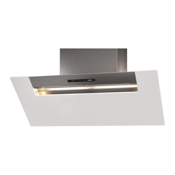
Hotte aspirante inclinée
FR
Cappa a parete (headfree)
IT
Hoofdvrije afzuigkap
NL
Headroom hood
EN
Ergoline 2
Gebrauchs- und Montageanleitung für die Modelle
DE
Manuel d'utilisation et de montage des modèles
FR
Istruzioni d'uso e di montaggio per i modelli
IT
Gebruiks- en montagehandleiding voor de modellen
NL
Operating and installation instructions for the models
EN
BKH 80 EG-2
BKH 90 EG-2
BKH 110 EG-2
BKH 120 EG-2
6003396_a
Chapitres
Table des Matières

Manuels Connexes pour Berbel Ergoline 2


Sommaire des Matières pour Berbel Ergoline 2
- Page 1 Kopffreihaube Hotte aspirante inclinée Cappa a parete (headfree) Hoofdvrije afzuigkap Headroom hood Ergoline 2 Gebrauchs- und Montageanleitung für die Modelle Manuel d’utilisation et de montage des modèles Istruzioni d‘uso e di montaggio per i modelli Gebruiks- en montagehandleiding voor de modellen Operating and installation instructions for the models BKH 80 EG-2 BKH 90 EG-2...
-
Page 32: Informations Sur Les Documents
Informations sur les documents Présentation des symboles dans le texte Appel à l‘action Manuel d‘utilisation et de montage pour : Hotte aspirante inclinée BKH 80 EG-2 Énumération Hotte aspirante inclinée BKH 90 EG-2 Hotte aspirante inclinée BKH 110 EG-2 Référence à d‘autres endroits dans ce document Hotte aspirante inclinée BKH 120 EG-2 Référence à... - Page 33 Sommaire Informations relatives à la sécurité ... . 34 Nettoyage ........53 Utilisation conforme .
-
Page 34: Informations Relatives À La Sécurité
Informations relatives à la sécurité Informations relatives à la sécurité Consignes de sécurité générales AVERTISSEMENT ! Utilisation conforme Danger en cas de non-respect du manuel d‘utilisation et de montage ! L‘appareil sert à aspirer les vapeurs de cuisson. Ce manuel comporte des informations importantes pour une L‘appareil est exclusivement conçu pour une utilisation utilisation sûre de l‘appareil. -
Page 35: Informations Sur Le Produit
Informations sur le produit Informations sur le produit Modes de fonctionnement L‘appareil est adapté pour les modes de fonctionnement suivants : Principe de fonctionnement Mode recyclage d’air Mode évacuation d’air vicié Mode hybride 2.2.1 Mode recyclage d’air Le contenu du filtre à recyclage d‘air neutralise les odeurs présentes. -
Page 36: Présentation Du Produit
Informations sur le produit Présentation du produit A Bornes de connexion pour caisson mural, interrupteur de contact de fenêtre (contact multifonctions) et connexion A Cheminée B Panneau de commande B Sortie du ventilateur avec auxiliaire de guidage pour filtre « 4.2 Panneau de commande » (page 49). ou conduite d’évacuation d’air vicié... -
Page 37: Étendue De Livraison
Informations sur le produit Étendue de livraison Caractéristiques techniques 230 V / 230 V / 230 V / 230 V / Tension de raccordement 50 Hz 50 Hz 50 Hz 50 Hz 187 W 187 W 193 W 193 W Puissance nominale Consommation 170 W... -
Page 38: Montage
Montage Montage Exigences relatives au lieu de montage AVERTISSEMENT ! Consignes de sécurité relatives au montage Danger de mort en cas de montage incorrect ! Le non-respect des conditions ambiantes peut entraîner des situations dangereuses, par ex. : lors de la manipulation de AVERTISSEMENT ! courant ou de gaz. -
Page 39: Exigences Relatives Aux Modes De Fonctionnement
Montage Exigences relatives aux modes de fonctionnement Exigences relatives à la conduite d‘évacuation d‘air vicié (uniquement en mode évacuation d‘air vicié D‘autres accessoires peuvent être nécessaires en fonction du ou hybride) mode de fonctionnement. « 9.2 Accessoires » (page 61). AVERTISSEMENT ! Risque d‘incendie et d‘asphyxie en cas de montage 3.3.1 Exigences relatives au mode recyclage d’air... -
Page 40: Étapes De Montage
Montage Étapes de montage 3.5.2 Déballage de l’appareil Brève présentation : ATTENTION ! 1. Préparation du montage 2. Déballage de l’appareil Risque de bris de verre ou autres dommages en cas de 3. Retrait de l‘enveloppe inférieure et du Capillar Trap manipulation incorrecte ! 4. -
Page 41: Retrait De L'enveloppe Inférieure Et Du
Montage 3.5.3 Retrait de l‘enveloppe inférieure et du Capillar Le Capillar Trap est inséré et maintenu en position au moyen Trap d‘une fixation latérale dans l‘appareil. ATTENTION ! Risque de dommages en cas de chute de pièces ! Lors du déplacement de l‘appareil, le panneau frontal peut s‘ouvrir et les pièces intérieures peuvent tomber. -
Page 42: Accrochage De L'appareil
Montage 3.5.4 Accrochage de l’appareil AVERTISSEMENT Danger mortel d‘explosions ou de choc électrique ! L’appareil est conçu pour l’accrochage aux murs. La cheminée Le perçage de conduites de gaz, d‘eau ou électriques peut peut être adaptée à la hauteur respective du plafond. entraîner des situations dangereuses. - Page 43 Montage a = 7 b = 3-6 Les vis de fixation supérieures sont serrées uniquement après Accrocher l’appareil aux points de fixation. avoir aligné l‘appareil. Les vis de fixation inférieures servent de protection contre les chutes et ne sont plus accessibles après accrochage de l‘appareil.
-
Page 44: Raccordement Des Accessoires
Montage 3.5.5 Raccordement des accessoires Le raccordement a lieu au moyen de bornes de câble sur un connecteur amovible sur le carter de ventilateur. Selon la situation de montage, l‘accessoire disponible est raccordé à la hotte : ATTENTION ! Caisson mural Interrupteur de contact de fenêtre Risque de dommages en cas de raccordement incorrect ! Manostat à... -
Page 45: Positionnement Du Filtre (En Mode Recyclage D'air Et En Mode Hybride)
Montage 3.5.6 Positionnement du filtre (en mode recyclage Mode hybride - Air vicié vers le haut d‘air et en mode hybride) Pour le montage du filtre, un raccordement de tuyau (ø 150 mm) est situé sur le carter de ventilateur comme auxiliaire de guidage. -
Page 46: Raccordement De La Conduite D'évacuation D'air Vicié (En Mode Évacuation D'air Vicié Et En Mode Hybride)
Montage 3.5.7 Raccordement de la conduite d‘évacuation 3.5.8 Exécution du raccordement de l‘alimentation d’air vicié (en mode évacuation d‘air vicié et électrique en mode hybride) Observer la tension indiquée sur la plaque signalétique. Mode évacuation d’air vicié Placer la conduite d‘évacuation d‘air vicié par le haut sur Insérer la fiche mâle dans la prise de raccordement du l’auxiliaire de guidage du carter du ventilateur. -
Page 47: Montage De La Cheminée
Montage 3.5.9 Montage de la cheminée La cheminée est composée de deux tôles insérées l‘une dans l‘autre. Les grilles d‘aération sont situées dans la tôle de cheminée intérieure. ATTENTION ! Risque de dommages en cas de manipulation incorrecte ! Le corps de la hotte et la cheminée peuvent être endommagés en cas de mouvements pendant le montage. -
Page 48: 3.5.10 Installer Capillar Trap Et L'enveloppe Inférieure
Montage 3.5.10 Installer Capillar Trap et l‘enveloppe inférieure Vérifier que l‘enveloppe inférieure est installée correctement et qu‘elle est maintenue par les aimants de Les pièces intérieures doivent être remises en place après le maintien. montage. Fermer le panneau frontal. Placer le Capillar Trap avec deux mains dans le bac de réception en réalisant un mouvement circulaire. -
Page 49: Utilisation
Utilisation Utilisation Mesures pour une alimentation suffisante en air frais : Ouvrir les fenêtres. Ouvrir les portes. S‘assurer que l‘interrupteur de contact de fenêtre et le Consignes de sécurité relatives à l’utilisation caisson mural sont installés et fonctionnels. Avec un lieu de combustion à air ambiant (par ex. : AVERTISSEMENT ! cheminée), dans la même composition d‘air : S’assurer que le dispositif de sécurité... -
Page 50: Fonctionnement Normal
Utilisation Fonctionnement normal Activer la hotte à un niveau de puissance supérieur si l‘intensité des vapeurs de cuisine ne diminue pas. Pendant la cuisson, en faisant revenir, commuter l’appareil Touche Fonction au niveau max de puissance. tactile Après la fin de la cuisson, utiliser la fonction arrêt temporisé... -
Page 51: Fonction Arrêt Temporisé
Utilisation 4.3.1 Fonction arrêt temporisé 4.3.2 Éclairage de la plaque de cuisson L’appareil dispose d’une fonction de temporisation. En L‘éclairage de la plaque de cuisson est équipé d’un éclairage utilisant cette fonction, l’appareil continue à fonctionner LED économe en énergie. L‘éclairage peut être utilisé à tout pendant 10 minutes au niveau de puissance sélectionné... -
Page 52: Affichage De Contrôle Du Remplissage Du
Utilisation 4.3.4 Affichage de contrôle du remplissage du filtre Touche Fonction L‘appareil dispose d‘un affichage de contrôle pour rappeler le tactile remplacement du remplissage du filtre. En mode recyclage Appuyer 1 fois sur la touche tactile. d‘air, l‘affichage de contrôle clignote toutes les 350 heures de L‘éclairage de la plaque de cuisson est activé. -
Page 53: Nettoyage
Nettoyage Nettoyage Consignes de nettoyage L‘appareil aspire les particules de saleté (par ex. : particules de graisse et d‘huile) présentes dans l‘air ambiant. Les particules Consignes de sécurité relatives au nettoyage de saleté sont séparées et collectées dans l‘enveloppe supérieure, dans l‘enveloppe inférieure et dans le Capillar Trap. - Page 54 Nettoyage Enveloppe supérieure et inférieure Capillar Trap L‘enveloppe supérieure est raccordée de manière fixe avec Le Capillar Trap est inséré et maintenu en position au moyen l‘appareil. d‘une fixation latérale dans l‘appareil. L‘enveloppe inférieure est fixée en positions finales et ne peut être retirée qu‘en position horizontale.
-
Page 55: Réparation
Réparation Réparation Entretien 6.2.1 Remplacement des ampoules Consignes de sécurité relatives à la réparation L’appareil est équipé d’un éclairage LED sans entretien. AVERTISSEMENT ! Lorsqu‘un défaut survient : S’adresser à votre revendeur spécialisé ou au service Danger en cas de non-respect des instructions de après-vente. -
Page 56: Hybride
Réparation Démonter le filtre hybride Enfoncer la tôle de cheminée intérieure vers le bas. Enlever la conduite d’évacuation d’air vicié du filtre hybride. Soulever le filtre d’au moins 30 mm. Sortir le filtre vers l’avant. Le remplacement du remplissage de filtre a lieu comme décrit dans le manuel correspondant. -
Page 57: Élimination Des Défauts
Réparation Élimination des défauts Le panneau de commande ne réagit pas malgré plusieurs pressions. Les défauts possibles sont décrits ci-après : Le panneau de commande est encrassé. Description du défaut. Nettoyer le panneau de commande. Cause possible. « 5. Nettoyage » (page 53). Solution. -
Page 58: Démontage
Démontage Démontage AVERTISSEMENT ! Risque de blessures en cas de manipulation incorrecte ! La taille et le poids de l‘appareil nécessitent beaucoup de force lors du décrochage. Si l‘appareil tombe, des blessures graves sont possibles. Décrocher l’appareil à deux personnes. Veiller à la stabilité lors du décrochage. S’assurer que personne d‘autre ne se trouve dans la zone de travail. -
Page 59: Élimination
Élimination Élimination Élimination de l’appareil ATTENTION ! Élimination de l‘emballage Risque d‘atteintes environnementales en cas d‘élimination incorrecte de l‘appareil ! La hotte est soumise à la directive européenne 2012/19/UE et ATTENTION ! ne doit pas être mise au rebut avec les déchets ménagers. Risque d‘atteintes environnementales en cas Ne pas éliminer l‘appareil avec les ordures ménagères à... -
Page 60: Annexe
33,3 33,3 BKH 80 EG-2 BKH 90 EG-2 Classe FDE Hood LE Hood 33,1 33,1 30,0 30,0 Classe LE Hood berbel BKH 80 EG-2 berbel BKH 90 EG-2 GFE Hood 88,5 88,5 85,3 85,3 Classe GFE Hood Débit volumétrique en mode évacuation d’air vicié... -
Page 61: Accessoires
Filtre hybride BHF 150 + 1003607 Filtre hybride BHF 150 + h 1004895 Fax : +49 (0) 5971 / 80 80 9 - 10 Kit de recharges berbel Pro Aktiv 150 1000875 Internet : www.berbel.de Manostat à ouverture minimale de pression P4 6001728 E-mail : info@berbel.de... - Page 152 6003396_a 27.03.2017...