GOK BC-1 Serie Notice De Montage Et De Service
Masquer les pouces
Voir aussi pour BC-1 Serie:
- Notice de montage (2 pages) ,
- Notice de montage et de service (96 pages)
Table des Matières
Publicité
Les langues disponibles
Les langues disponibles
Liens rapides
Montage- und Bedienungsanleitung
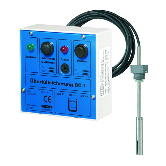
Überfüllsicherung Typ BC-1
zur Überwachung von Tanks mit flüssigen Betriebsmedien
als Alarmeinrichtung beim Befüllvorgang
INHALTSVERZEICHNIS
INFORMATION FÜR DEN ANLAGENBETREIBER .................................................................................. 2
ZU DIESER ANLEITUNG ......................................................................................................................... 2
ALLGEMEINE PRODUKTINFORMATION ............................................................................................... 2
ZULASSUNG ........................................................................................................................................... 2
SICHERHEITSBEZOGENE HINWEISE ................................................................................................... 3
PRODUKTBEZOGENE SICHERHEITSHINWEISE .................................................................................. 3
BESTIMMUNGSGEMÄSSE VERWENDUNG .......................................................................................... 3
NICHT BESTIMMUNGSGEMÄSSE VERWENDUNG ............................................................................... 4
QUALIFIKATION DER ANWENDER ........................................................................................................ 5
FUNKTIONSBESCHREIBUNG........... ..................................................................................................... 5
AUFBAU .................................................................................................................................................. 6
GEWÄHRLEISTUNG ............................................................................................................................... 6
TECHNISCHE ÄNDERUNGEN ................................................................................................................ 6
KONFORMITÄTSERKLÄRUNG ............................................................................................................... 6
ÜBEREINSTIMMUNGSERKLÄRUNG ...................................................................................................... 6
MONTAGE ............................................................................................................................................... 7
ELEKTRISCHER ANSCHLUSS ............................................................................................................. 11
INBETRIEBNAHME ............................................................................................................................... 14
BEDIENUNG .......................................................................................................................................... 15
FUNKTIONSPRÜFUNG .....................................................................................................................
FEHLERMELDUNG / BEDEUTUNG ...................................................................................................... 15
WARTUNG ............................................................................................................................................ 16
INSTANDSETZUNG .............................................................................................................................. 17
ENTSORGEN ........................................................................................................................................ 17
TECHNISCHE DATEN ........................................................................................................................... 18
EINBAUBESCHEINIGUNG DES FACHBETRIEBES .............................................................................. 19
Originalanleitung / Artikel-Nr. 15 700 50 i
BC-1-4
BC-1-2
Ausgabe 12.2018 / Ersatz für Ausgabe 08.2017
15
Publicité
Chapitres
Table des Matières

Manuels Connexes pour GOK BC-1 Serie


Sommaire des Matières pour GOK BC-1 Serie
-
Page 1: Table Des Matières
Montage- und Bedienungsanleitung Überfüllsicherung Typ BC-1 zur Überwachung von Tanks mit flüssigen Betriebsmedien als Alarmeinrichtung beim Befüllvorgang BC-1-4 BC-1-2 INHALTSVERZEICHNIS INFORMATION FÜR DEN ANLAGENBETREIBER .................. 2 ZU DIESER ANLEITUNG ......................... 2 ALLGEMEINE PRODUKTINFORMATION ....................2 ZULASSUNG ............................2 SICHERHEITSBEZOGENE HINWEISE ....................3 PRODUKTBEZOGENE SICHERHEITSHINWEISE .................. -
Page 2: Information Für Den Anlagenbetreiber
Überfüllsicherung Typ BC-1 INFORMATION FÜR DEN ANLAGENBETREIBER Lassen Sie sich bitte auf der Einbaubescheinigung des Fachbetriebes (siehe auf den letzten beiden Seiten) von Ihrem Fachbetrieb den ordnungsgemäßen Einbau der Überfüllsicherung bestätigen. ZU DIESER ANLEITUNG • Diese Anleitung ist ein Teil des Produktes. •... -
Page 3: Sicherheitsbezogene Hinweise
• JGS (Jauche, Gülle und Silagesickersäfte) • Harnstofflösung • Heizöl schwer • Heizöl Bio Eine Liste der Betriebsmedien mit Angabe der Bezeichnung, der Norm und des Verwendungslandes erhalten Sie im Internet unter www.gok-online.de/de/downloads/technische-dokumentation. Artikel-Nr. 15 700 50 i 3 / 20... -
Page 4: Nicht Bestimmungsgemässe Verwendung
Überfüllsicherung Typ BC-1 Betreiberort Betrieb in explosionsgefährdeten Bereichen nicht zulässig! Kann zu Explosion oder schweren Verletzungen führen. Anzeigegerät: • Typ BC-1-1, Typ BC-1-3, Typ BC-1-4, mit Schutzart IP30, in trockenen und geschützten Räumen • Typ BC-1-2, mit Schutzart IP65, im Innen- und wettergeschützten Außenbereich Sonde: •... -
Page 5: Qualifikation Der Anwender
Überfüllsicherung Typ BC-1 QUALIFIKATION DER ANWENDER Mit der MONTAGE, INBETRIEBNAHME, WARTUNG und INSTANDSETZUNG dieses Produktes dürfen nur solche Betriebe beauftragt werden, die für diese Tätigkeiten Fachbetriebe im Sinne von § 62 der AwSV sind. Dieses trifft nicht zu, wenn die Anlage von der Fachbetriebspflicht ausgenommen ist. -
Page 6: Aufbau
Daten, Druckfehler und Irrtümer vorbehalten. Alle Abbildungen dienen illustrativen Zwecken und können von der tatsächlichen Ausführung abweichen. KONFORMITÄTSERKLÄRUNG Die Konformitätserklärung vom Hersteller für dieses Produkt erhalten Sie im Internet unter: http//www.gok-online.de/de/ zertifikate/konformitaetserklaerungen.php ÜBEREINSTIMMUNGSERKLÄRUNG Die Übereinstimmungserklärung vom Hersteller für dieses Produkt erhalten Sie im Internet unter: http//www.gok-online.de/de/... -
Page 7: Montage
Überfüllsicherung Typ BC-1 MONTAGE Alle elektrischen Arbeiten sind grundsätzlich von einer ausgebildeten Elektrofachkraft auszuführen. Schweiz: Der Einbau darf nur von fachkundigen Personen ausgeführt werden, die über Kenntnisse in Elektrotechnik sowie Explosions- und Brandschutz verfügen. Die für die Durchführung von Bauvorhaben gesetzlich vorgeschriebenen Genehmigungen, Zustimmungen und Bescheinigungen werden durch die Allgemeine bauaufsichtliche Zulassung und diese Montage- und Bedienungsanleitung nicht ersetzt. - Page 8 Überfüllsicherung Typ BC-1 Montage Sonde Einstellmaß X Das Einstellmaß X ist der Abstand zwischen der Bezugskante Domdeckel bzw. Einbaukörper und dem Markierungsring auf der Schutzhaube des Fühlers am unteren Ende der Sonde. Kontrollmaß Y Das Kontrollmaß Y ergibt sich aus der Differenz zwischen Sondenmaß...
- Page 9 Überfüllsicherung Typ BC-1 Berechnungsmöglichkeit für das Einstellmaß X a = Maß a= H - L H = Höhe oder Durchmesser des Tanks b = Tankwanddicke = Höhe Muffe oder Gewindeflansch 1. Maximale Volumenstrom der Förderpumpe des l/min Straßentankfahrzeuges 2. Schalt- und Schließverzögerungszeiten der Förderpumpe Zeit des Straßentankfahrzeuges Standaufnehmer laut Messung / Datenblatt...
- Page 10 Überfüllsicherung Typ BC-1 Montage Einbaukörper Nach zuvor erfolgter Ermittlung des Einstellmasses X ist der Einbaukörper zu arretieren. Der Einbaukörper dient zur Befestigung der Sonde im Tank. Der Einbaukörper besitzt Feststellschrauben, die das Sondenrohr gegen Verschieben sichern. Einbaukörper unter Verwendung einer Dichtung oder von Dichtmitteln von Hand einschrauben und fest anziehen.
-
Page 11: Elektrischer Anschluss
Überfüllsicherung Typ BC-1 Einbaukörper G 3/4 • Feststellschraube am Einbaukörper lösen. • Ermitteltes Einstellmaß X einstellen. • Feststellschraube und Kabelverschraubung fest anziehen, damit sich das Sondenrohr nicht mehr verschieben lässt. Sondenrohr nicht mehr verschieben lässt. Am Tank vorhandene größere Anschlussgewinde als G1 können durch Verwendung handelsüblicher Reduzierstücke auf Anschlussgewinde G1 des Einbaukörpers gebracht werden. -
Page 12: Elektrische Installation
Überfüllsicherung Typ BC-1 Anzeigegerät Typ BC-1-1 und BC-1-2 – Anzeigegerät Typ BC-1-4 – Schnittdarstellung Schnittdarstellung Elektrische Installation Lebensgefahr durch Stromschlag! Stromschlag durch Berührung spannungsführender Teile. Vor Öffnen des Gehäuses, spannungsfrei schalten. Erst nach Beenden der Arbeit mit Spannung beaufschlagen. Verbindungsleitung zwischen Anzeigegerät und Sonde Leitungsquerschnitt 2 x 1 mm (Cu) - Page 13 Überfüllsicherung Typ BC-1 Dies kann durch Betätigen des Tasters Prüfen am Messumformer vorgenommen werden - dadurch erfolgt eine Alarmmeldung und evtl. angeschlossene Melde- und Steuerungseinrichtungen werden dabei geschaltet. Nach Loslassen des Tasters Prüfen erlischt die Alarmmeldung wieder. Die FUNKTIONSPRÜFUNG ersetzt nicht die jährlich durchzuführende Prüfung (siehe Abschnitt WARTUNG).
-
Page 14: Inbetriebnahme
Überfüllsicherung Typ BC-1 Anschluss externer Taster zur Alarmabschaltung Es darf keine Fremdspannung an die Klemmen 9 + 10 oder an die Klemmen 13 + 14 angelegt werden! Das Anzeigegerät verfügt über einen Eingang für einen externen Quittiertaster (Klemmen 9 + 10). Die Funktion entspricht dem im Anzeigegerät integrierten Taster Alarmton Quittieren, mit dem bei Alarmgabe der akustische Alarm sowie der Ausgang Alarm 2 quittiert (abgeschaltet) werden kann. -
Page 15: Bedienung
Überfüllsicherung Typ BC-1 BEDIENUNG Das Anzeigegerät muss den Überwachungsmodus durch die grüne LED Betrieb ständig anzeigen. Vor jeder Befüllung ist eine FUNKTIONSPRÜFUNG durch Betätigen des Tasters Prüfen vorzunehmen (einschließlich der optional angeschlossenen Melde- oder Steuerungseinrichtungen mit Stellglied). Bei einer Befüllung des Tanks erfolgt bei Erreichen der Ansprech-Füllhöhe (entsprechend dem Einstellmaß... -
Page 16: Wartung
Überfüllsicherung Typ BC-1 *1 Ausgang Betrieb nur bei Typ BC-1-1, BC-1-2 und BC-1-4 Die Relais-Ausgänge Alarm 1 und Alarm 2 sind nicht überwacht, d.h. eine Leitungsunterbrechung oder ein Kurzschluss zu angeschlossenen Melde- oder Steuerungseinrichtungen wird durch den Messumformer nicht erkannt und angezeigt. WARTUNG Lebensgefahr durch Stromschlag! Stromschlag durch Berührung spannungsführender Teile. -
Page 17: Instandsetzung
Elektrogeräte der Marke „GOK“ nach Nutzungsbeendigung auf eigene Kosten gemäß den Richtlinien des Elektro- und Elektronikgerätegesetzes (ElektroG) ordnungsgemäß zu entsorgen. Damit wird die GOK Regler- und Armaturen- Gesellschaft mbH & Co. KG von den Verpflichtungen nach § 10 Abs. 2 ElektroG und damit im Zusammenhang stehender Ansprüche Dritter freigestellt. -
Page 18: Technische Daten
Überfüllsicherung Typ BC-1 TECHNISCHE DATEN Anzeigegerät Versorgungsspannung 230 V AC; 50 – 60 Hz Leistungsaufnahme 4,5 VA Spannungstoleranz + 10 %/ - 15 % IP30 nach EN 60529 (BC-1-1, BC-1-3, BC-1-4) Schutzart IP65 nach EN 60529 (BC-1-2) Gehäuse PE oder PC Abmessungen H x B X T Typ BC-1-1... -
Page 19: Einbaubescheinigung Des Fachbetriebes
• Wichtig für eventuelle Gewährleistungsansprüche! Hiermit bestätige ich die Überfüllsicherung Typ BC-1 ordnungsgemäßen MONTAGE GOK-Geräte-Nr: folgender Sicherheitseinrichtung: entsprechend der gültigen Montage- und Bedienungsanleitung. Nach Abschluss der MONTAGE wurde die Sicherheitseinrichtung der INBETRIEBNAHME und einer FUNKTIONSPRÜFUNG unterzogen. Die Sicherheitseinrichtung arbeitete zum Zeitpunkt der INBETRIEBNAHME störungsfrei. - Page 20 Pikketdienst und Telefonnummer anzubringen! Regler- und Armaturen-Gesellschaft mbH & Co. KG Obernbreiter Straße 2-18 • 97340 Marktbreit / Germany Tel.: +49 9332 404-0 • Fax: +49 9332 404-43 E-Mail: info@gok-online.de • www.gok-online.de • www.gok-blog.de 20 / 20 Artikel-Nr. 15 700 50 i...
- Page 21 Assembly and operating manual Overfill prevention device type BC-1 to monitor tanks with liquid operating media as an alarm feature during the filling process BC-1-4 BC-1-2 CONTENTS INFORMATION FOR THE PLANT OPERATOR ..................2 ABOUT THE MANUAL ..........................2 GENERAL PRODUCT INFORMATION ....................2 APPROVAL ..............................
-
Page 22: Information For The Plant Operator
Overfill prevention device type BC-1 INFORMATION FOR THE PLANT OPERATOR Please ask your specialised company to confirm the proper installation of the overfill sensor on the installation certificate of the specialised company (see the last two pages). ABOUT THE MANUAL •... -
Page 23: Safety Advice
• JGS (liquid manure, semi-liquid manure and ® (AdBlue silage effluent) You will find a list of operating media with descriptions, the relevant standards and the country in which they are used in the Internet at www.gok-online.de/de/downloads/technische-dokumentation. part no. 15 700 51 g 3 / 20... -
Page 24: Inappropriate Use
Overfill prevention device type BC-1 Place of operation May not be used in potentially explosive areas. Can cause an explosion or serious injuries. Indicator: • type BC-1-1, type BC-1-3, type BC-1-4, with protection type IP30, in dry and protected rooms •... -
Page 25: User Qualification
Overfill prevention device type BC-1 USER QUALIFICATION INSTALLATION, START-UP, MAINTENANCE and RESTORATION of the product may only be commissioned to such companies constituting specialised companies for this work in the meaning of § 62 of the AwSV. This does not apply if the system is excluded from this obligation to be installed by a specialised company according to national regulations. -
Page 26: Design
DECLARATION OF CONFORMITY You will find the manufacturer’s declaration of conformity for this product on the website: http//www.gok-online.de/en/certificate/ declaration of conformity.php DECLARATION OF COMPLIANCE You will find the manufacturer‘s declaration of compliance for this product on the website: http//www.gok-online.de/en/certificate/... -
Page 27: Assembly
Overfill prevention device type BC-1 ASSEMBLY Electric work is always to be carried out by a trained electrician. Switzerland: The installation may only be carried out by experts with knowledge in electrical engineering as well as regarding explosion and fire protection. The permits, approvals, and certificates legally required for the execution of building projects are not replaced by the general building permit and this assembly and operating manual. - Page 28 Overfill prevention device type BC-1 ASSEMBLY OF THE PROBE Adjusting dimension X The adjusting dimension X is the distance between the reference edge between the dome cover or screw-in unit and the marking ring on the protective cover of the sensor at the lower end of the probe.
- Page 29 Overfill prevention device type BC-1 Calculation option for the adjusting dimension X a = dimension a= H - L H = height or diameter of the tank b = tank wall thickness = height bushing or threaded flange 1. Maximum volumetric flow rate of the booster pump of the road tanker l/min Time 2.
- Page 30 Overfill prevention device type BC-1 Assembly insert After having determined the adjusting dimension X, the insert must be locked. The insert is used to fasten the probe within the tank. The insert has locking screws which secure the probe tube against moving. Manually screw-in and fasten the insert using a gasket or sealing materials.
-
Page 31: Electric Connection
Overfill prevention device type BC-1 Insert G 3/4 • loosen the locking screw on the insert. • set the determined adjusting dimension X. • tighten the locking screw so that the probe tube cannot be moved. Connecting threads present on the tank larger than G1 can be brought to the connecting thread G1 of the insert by using commercially available reducers. -
Page 32: Electrical Installation
Overfill prevention device type BC-1 The display unit must be connected to an overcurrent protective equipment (OCP) which is easy to reach. Indicator Type BC-1-1 and BC-1-2 – Indicator type BC-1-4 – Sectional View Sectional View Electrical Installation Danger to life due to electric shock! Electric shock from touching live parts. - Page 33 Overfill prevention device type BC-1 (including the connected signalling and control devices with actuator) must be carried out before each filling. This can be done by pushing the Prüfen [Test] button at the measuring transducer – this leads to an alarm signal, and possibly connected signalling and control devices are switched. After release of the Prüfen [Test] button, the alarm signal goes out.
-
Page 34: Start-Up
Overfill prevention device type BC-1 determined by the effective volume according to section 20 VWF – when operating the sensor at the latest and prior to closing the automatic shut-off device. Connection of External Buttons for Alarm Deactivation No extraneous voltage may be applied to terminal 9 + 10 or to terminal 13 + 14! The indicator has an input for an external acknowledgement button (Terminals 9 + 10). -
Page 35: Operation
Overfill prevention device type BC-1 OPERATION The indicator must indicate the monitoring mode constantly via the green LED Betrieb [Operation]. Before each filling process, a FUNCTION CHECK must be carried out by pressing the Test button (including any connected signalling or control devices with actuator). During a filling of the tank, an alarm is indicated via the red LED Alarm, the integrated buzzer, and any connected external alarm units when the response level is reached (according to the adjusting dimension X of the probe) so that the filling procedure can be ended on time. -
Page 36: Maintenance
Overfill prevention device type BC-1 *1 Output Betrieb [Operation] only with type BC-1-1, BC-1-2 and BC-1-4 The relay outputs Alarm 1 and Alarm 2 are not monitored, i.e. a line disconnection or a short circuit to the connected signalling and control devices is not recognised and indicated by the measuring transducer. -
Page 37: Restoration
The commercial customer (owner) is obligated to properly dispose of the electronic devices of the “GOK” brand delivered to them at their own expense in accordance with the provisions in the Elektro- und Elektronikgerätegesetz (ElektroG) [Electrical and Electronic Equipment Act] after termination of the use thereof. -
Page 38: Technical Data
Overfill prevention device type BC-1 TECHNICAL DATA Indicator Supply voltage 230V AC; 50-60Hz Power consumption 4.5VA Voltage tolerance +10% / -15% Protection type IP30 acc. to EN 60529 (BC-1-1, BC-1-3, BC-1-4) IP65 acc. to EN 60529 (BC-1-2) Housing Polyester or polycarbonate Dimensions H x W x D Type BC-1-1... -
Page 39: Installation Certificate From Specialised Company
Overfill sensor type BC-1 I hereby confirm that the following safety equipment was installed correctly: GOK device no.: in accordance with the applicable assembly and operating manual. After ASSEMBLY, the safety equipment underwent the start-up and a FUNCTION CHECK. Upon start-up, the safety equipment operated properly. - Page 40 BC-1! Regler- und Armaturen-Gesellschaft mbH & Co. KG Obernbreiter Straße 2-18 • 97340 Marktbreit / Germany Tel.: +49 9332 404-0 • Fax: +49 9332 404-43 E-Mail: info@gok-online.de • www.gok-online.de • www.gok-blog.de 20 / 20 part no. 15 700 51 g...
- Page 41 Notice de montage et de service Dispositif anti-débordement type BC-1 pour surveiller des citernes avec milieux liquides comme dispositif d'alarme lors du remplissage BC-1-4 BC-1-2 TABLE DES MATIÈRES INFORMATION POUR L'EXPLOITANT DE L'INSTALLATION ..............1 À PROPOS DE CETTE NOTICE ......................2 INFORMATIONS GÉNÉRALES SUR LE PRODUIT .................
-
Page 42: Information Pour L'exploitant De L'installation
Dispositif anti-débordement type BC-1 INFORMATION POUR L'EXPLOITANT DE L'INSTALLATION Veuillez faire confirmer par votre entreprise spécialisée le montage conforme du dispositif anti-débordement sur le certificat d'installation de l'entreprise spécialisée (voir les deux dernières pages). À PROPOS DE CETTE NOTICE • La présente notice fait partie intégrante du produit. •... -
Page 43: Consignes De Sécurité
Dispositif anti-débordement type BC-1 CONSIGNES DE SÉCURITÉ Nous attachons une importance cruciale à votre sécurité et à celle d’autrui. Aussi avons nous mis à votre disposition, dans cette notice de montage et service, un grand nombre de consignes de sécurité des plus utiles. Veuillez lire et observer toutes les consignes de sécurité... -
Page 44: Lieu D'exploitation
Dispositif anti-débordement type BC-1 Vous trouverez une liste des fluides d’exploitation utilisés avec indication de la désignation, de la norme et du pays d’utilisation sur Internet à l’adresse www.gok-online.de/de/downloads/technische-dokumentation. Lieu d'exploitation Utilisation en atmosphères explosibles inadmissible ! Peut provoquer une explosion ou entraîner des blessures graves. -
Page 45: Qualification Des Utilisateurs
Dispositif anti-débordement type BC-1 QUALIFICATION DES UTILISATEURS Seules des entreprises qui sont des entreprises spécialisées dans ce domaine conformément à l'art. 62 de la Directive AwSV peuvent être chargées du MONTAGE, de la MISE EN SERVICE, de L'ENTRETIEN et de la RÉPARATION du produit. La règle susmentionnée n'est pas applicable si les dispositions de la législation nationale ne prévoient pas pour l'installation respective une telle obligation de charger une entreprise spécialisée. -
Page 46: Structure
Toutes les images sont représentées à titre d’illustration et peuvent différer de la réalité. DÉCLARATION DE CONFORMITÉ Vous trouverez la déclaration de conformité du fabricant pour ce produit sur le site internet : http//www.gok-online.de/de/ zertifikate/konformitaetserklaerungen.php 6 / 20 référence 15 700 52 f... -
Page 47: Montage
Dispositif anti-débordement type BC-1 MONTAGE Avant le montage, vérifier si le produit fourni a été livré dans son intégralité et s'il présente d'éventuelles avaries de transport. Les travaux électriques sont à réaliser par un électricien qualifié. Ces exigences s'appliquent également à la mise en service, à l'entretien et à la réparation de le dispositif anti- débordement. -
Page 48: Montage De La Sonde
Dispositif anti-débordement type BC-1 MONTAGE DE LA SONDE Cote de réglage X La cote de réglage X est la distance entre le bord de référence du couvercle de puits ou de l'insert à visser et l'anneau de marquage sur le capot de protection du détecteur à l'extrémité inférieure de la sonde. - Page 49 Dispositif anti-débordement type BC-1 Possibilité de calcul pour la cote de réglage X a = cote a= H - L H = hauteur ou diamètre de la citerne b = épaisseur de la paroi de la citerne = hauteur du manchon ou de la bride filetée 1.
- Page 50 Dispositif anti-débordement type BC-1 Montage de la pièce d'insert Après avoir déterminé la cote de réglage X, la pièce d'insert doit être arrêtée. La pièce d'insert sert à la fixation de la sonde sur la citerne. La pièce d’insert comporte des vis d'arrêt, qui empêchent le tube de sonde de se déplacer. Introduisez la pièce d’insert sans oublier d'interposer un joint ou un matériau d'étanchéité...
-
Page 51: Raccordement Électrique
Dispositif anti-débordement type BC-1 Pièce d'insert G 3/4 • desserrer la vis d'arrêt sur la pièce d'insert. • régler la cote de réglage X déterminée. • bien serrer la vis d'arrêt afin que la tube de sonde puisse plus être déplacée. Des filets de raccordement sur la citerne dont la dimension dépasse celle de G1 peuvent être adaptés à... -
Page 52: Détecteur
Dispositif anti-débordement type BC-1 Dispositif d'affichage type BC-1-1 et Appareil indicateur Type BC-1-4 BC-1-2 - vue en coupe - vue en coupe Installation électrique Danger de mort par décharge électrique ! Décharge électrique par contact avec des pièces sous tension. Mettre hors tension avant l'ouverture du boîtier. -
Page 53: Fonctionnement
Dispositif anti-débordement type BC-1 Vous pouvez le faire en appuyant sur le bouton-poussoir Prüfen du capteur de mesure. Vous déclencherez ainsi l'alarme et activerez les dispositifs d'avertissement et de commande éventuellement connectés. L'alarme cesse quand vous relâchez le bouton-poussoir Prüfen. L'essai mentionné... -
Page 54: Mise En Service
Dispositif anti-débordement type BC-1 Connexion d'un bouton-poussoir externe pour exclusion des alarmes Aucune tension parasite ne doit être appliquée sur la borne 9 + 10 ou la borne 13 + 14 ! L'appareil indicateur dispose d'une entrée pour une touche d'acquittement externe (clip 9 + 10). -
Page 55: Commande
Dispositif anti-débordement type BC-1 COMMANDE L'appareil indicateur doit témoigner en permanence qu'il est en mode audit en allumant sa LED verte Betrieb (fonctionnement). Lors du remplissage de la citerne, lorsque le niveau atteint la hauteur de remplissage (correspondant à la cote de réglage X de la sonde), la LED rouge Alarm (alarme) et le signal sonore intégré... -
Page 56: Entretien
Dispositif anti-débordement type BC-1 Interruption MARCHE MARCHE MARCHE MARCHE MARCHE au niveau de la conduite entre le capteur de mesure et la sonde ou au niveau de la thermistance Court-circuit MARCHE MARCHE MARCHE MARCHE MARCHE au niveau de la conduite entre le capteur de mesure et la sonde ou au niveau de la thermistance... -
Page 57: Réparation
électriques et électroniques usagés avec les déchets domestiques. Le client exclusivement commercial (propriétaire) s’engage à éliminer à ses frais les appareils électriques de la marque « GOK » qui lui étaient livrés une fois leur utilisation terminée conformément aux directives de l'Elektro- und Elektronikgerätegesetz (ElektroG) [Loi relative aux appareils électriques et... -
Page 58: Données Techniques
Dispositif anti-débordement type BC-1 DONNÉES TECHNIQUES Appareil indicateur Tension d'alimentation 230 V AC ; 50 - 60 Hz Puissance absorbée 4,5 VA Tolérance de tension + 10 % / - 15 % Type de protection IP30 selon EN 60529 (BC-1-1, BC-1-3, BC-1-4) IP65 selon EN 60529 (BC-1-2) Boîtier Polyester ou polycarbonate... -
Page 59: Certificat D'installation De L'entreprise Spécialisée
Dispositif anti-débordement type BC-1 Je certifie par la présente l'installation correcte du dispositif N° de l'appareil GOK : de sécurité suivant : selon la notice de montage et de service applicable. Après l'achèvement du MONTAGE, le dispositif de sécurité a été soumis à la mise en service et à un ESSAI DE FONCTIONNEMENT. -
Page 60: Essai De Fonctionnement Périodique
! Regler- und Armaturen-Gesellschaft mbH & Co. KG Obernbreiter Straße 2-18 • 97340 Marktbreit / Germany Tel.: +49 9332 404-0 • Fax: +49 9332 404-43 E-Mail: info@gok-online.de • www.gok-online.de • www.gok-blog.de 20 / 20 référence 15 700 52 f... - Page 61 Montage- en gebruiksaanwijzing Overvulbeveiliging type BC-1 ter bewaking van tanks met vloeibare bedrijfsmedia als alarmvoorziening bij het vulproces BC-1-4 BC-1-2 INHOUDSOPGAVE INFORMATIE VOOR DE EXPLOITANT VAN DE INSTALLATIE .............. 2 OVER DEZE HANDLEIDING ........................2 ALGEMENE PRODUCTINFORMATIE ..................... 2 TOELATING ............................. 2 VEILIGHEIDSVOORSCHRIFTEN ......................
-
Page 62: Informatie Voor De Exploitant Van De Installatie
Overvulbeveiliging type BC-1 INFORMATIE VOOR DE EXPLOITANT VAN DE INSTALLATIE Laat uw installateur in de inbouwverklaring (zie op de laatste pagina's) bevestigen, dat de inbouw van de overvulbeveiliging correct uitgevoerd is. OVER DEZE HANDLEIDING • Deze handleiding maakt deel uit van het product. •... -
Page 63: Veiligheidsvoorschriften
Overvulbeveiliging type BC-1 VEILIGHEIDSVOORSCHRIFTEN Wij hechten veel waarde aan uw veiligheid en die van anderen. Daarom hebben we in deze montage- en gebruiksaanwijzing veel belangrijke veiligheidsvoorschriften opgenomen. Wij verzoeken u alle veiligheidsvoorschriften en overige instructies te lezen en op te volgen. -
Page 64: Onreglementair Gebruik
Overvulbeveiliging type BC-1 Een lijst van bedrijfsmedia met opgave van de aanduiding, de norm en het gebruiksland vindt u op www.gok-online.de/de/downloads/technische-dokumentation. Plaats van toepassing Niet gebruiken in explosiegevaarlijke omgevingen! Kan een explosie of zware verwondingen veroorzaken. Indicator: • type BC-1-1, type BC-1-3, type BC-1-4, met beschermingsgraad IP30, in droge en beschermde ruimtes •... -
Page 65: Kwalificatie Van De Gebruikers
Overvulbeveiliging type BC-1 Verkeerd gebruik en misbruik kunnen leiden tot gevaren voor gezondheid en leven van installateur en exploitant, tot gevaren voor het apparaat en andere goederen van de exploitant en tot storingen van het apparaat zelf. KWALIFICATIE VAN DE GEBRUIKERS Met MONTAGE, INBEDRIJFSTELLING, ONDERHOUD en REPARATIE van de product mogen alleen bedrijven worden belast, die voor deze werkzaamheden installateurs zijn in de zin van §... -
Page 66: Installatie
Alle afbeeldingen zijn bedoeld ter illustratie en kunnen afwijken van de feitelijke uitvoering. CONFORMITEITSVERKLARING De conformiteitsverklaring van de fabrikant voor dit product vindt u op internet op: http//www.gok-online.de/de/ zertifikate/konformitaetserklaerungen.php VERKLARING VAN OVEREENSTEMMING De verklaring van overeenstemming van de fabrikant voor dit product vindt u op internet op: http//www.gok-online.de/de/... -
Page 67: Montage
Overvulbeveiliging type BC-1 MONTAGE Elektrische werkzaamheden moeten principieel door een opgeleide elektricien worden uitgevoerd. Deze vereisten gelden ook voor de inbedrijfstelling, het onderhoud en de reparatie van de overvulbeveiliging. Zwitserland: De inbouw mag uitsluitend worden uitgevoerd door deskundige personen, die over kennis van elektrotechniek en explosie- en brandbeveiliging beschikken. -
Page 68: Montage Sonde
Overvulbeveiliging type BC-1 MONTAGE SONDE Instelmaat X De instelmaat X is de afstand tussen de referentierand mangatdeksel resp. inschroefstuk en de markeerring op de beschermkap van de voeler aan het onderste uiteinde van de sonde. Controlemaat Y De controlemaat Y is het resultaat van het verschil tussen sondemaat Z en instelmaat X. - Page 69 Overvulbeveiliging type BC-1 Mogelijke berekening voor de instelmaat X a = maat a= H - L H = hoogte of diameter van de tank b = dikte van de tankwand = hoogte mof of draadflens 1. Maximaal debiet van de transportpomp van de tankwagen l/min 2.
- Page 70 Overvulbeveiliging type BC-1 Montage inbouwelement Na VASTSTELLING VAN DE INSTELMAAT X moet het inbouwelement worden vergrendeld. Het inbouwelement dient ter bevestiging van de sonde in de tank. Het inbouwelement beschikt over vastzetschroeven, die de sondebuis zekeren tegen verschuiven. Schroef het inbouwelement met gebruikmaking van een afdichting of van dichtmiddelen handmatig vast en span het strak aan.
-
Page 71: Elektrische Aansluiting
Overvulbeveiliging type BC-1 Inbouwelement G 3/4 • vastzetschroef aan het inbouwelement losdraaien. • vastgestelde instelmaat X instellen. • vastzetschroef vastdraaien, zodat de sondebuis niet meer verschoven kan worden. Op de tank aanwezige grotere aansluitdraden dan G1 kunnen door gebruik van gangbare reduceerstukken tot aansluitdraad G1 van het inbouwelement worden teruggebracht. -
Page 72: Elektrische Installatie
Overvulbeveiliging type BC-1 De aansluiting van externe leidingen (netspanning, voeler enz.) geschiedt middels veerkrachtklemmen (toegestane doorsnede van de aansluitleidingen tot 2,5 mm²). De indicator moet op een overstroomveiligheidsvoorziening OCP (Over Current Protection) aangesloten worden, die eenvoudig bereikbaar is. Indicator type BC-1-1 en BC-1-2 – Indicator type BC-1-4 doorsnede doorsnede Elektrische installatie... - Page 73 Overvulbeveiliging type BC-1 Aansluiting uitgangen - potentiaalvrije relaiscontacten aan de indicator De indicator beschikt over 3 potentiaalvrije relaiscontacten. De uitgangen Alarm 1 en Alarm 2 zijn voorzien voor het aansturen van externe alarmapparaten (ter aansluiting van de meld- of aanstuurinrichting van de overvulbeveiliging). De uitgang Betrieb [Bedrijf] is voorzien voor de aansluiting van een externe bedrijfsindicatie (lamp).
-
Page 74: Inbedrijfstelling
Overvulbeveiliging type BC-1 Aanwijzingen voor Zwitserland Voor afsluitorganen en transportpompen in Zwitserland moet met het volgende rekening worden gehouden: Deze inrichtingen zijn per installatie zeer verschillend en kunnen niet algemeen worden gespecificeerd. In het bijzonder moet de exploitant van de installatie een geschikt, door de speciale vulbeveiliging automatisch aangestuurd afsluitorgaan inbouwen (bijv. -
Page 75: Bediening
Overvulbeveiliging type BC-1 De sonde mag bij deze test niet in bedrijfsmedium ondergedompeld zijn. Sonde naar buiten trekken. Levensgevaar door stroomstoot! Stroomstoot door aanraking van onder spanning staande onderdelen. Spanningsloos schakelen. De sonde enkel aanraken wanneer de indicator niet meer onder spanning staat. -
Page 76: Foutmelding/Betekenis
Overvulbeveiliging type BC-1 FOUTMELDING/BETEKENIS Toestand van Bedrijfs-led + Alarm- Alarm- Bedrijfstoestand Uitgang Uitgang Alarm 1 Alarm 2 uitgang Bedrijf *1 zoemer Normaal bedrijf (vulniveau onder het sonde- aanspreekniveau) Alarm Vulniveau bereikt sonde- aanspreekniveau bij het vullen Alarm bevestigd (met knop) Uitval van de hulpenergie Onderbreking aan de leiding tussen... -
Page 77: Reparatie
De uitsluitend commerciële klant (eigenaar) aanvaardt de plicht, de aan hem geleverde elektrische toestellen van het merk ‘GOK’ na beëindiging van hun gebruik op eigen kosten naar behoren af te voeren overeenkomstig de richtlijnen van het Elektro- und Elektronikgerätegesetz (ElektroG). -
Page 78: Technische Gegevens
Overvulbeveiliging type BC-1 TECHNISCHE GEGEVENS Indicator Voedingsspanning 230 V AC; 50 – 60 Hz Opgenomen vermogen 4,5 VA Spanningstolerantie + 10 % / - 15 % IP30 volgens EN 60529 (BC-1-1, BC-1-3, BC-1-4) Beschermingsgraad IP65 volgens EN 60529 (BC-1-2) Behuizing Polyester of polycarbonaten Afmetingen H x B X D... -
Page 79: Inbouwverklaring Van De Installateur
• Belangrijk voor eventuele aanspraak op garantie! Overvulbeveiliging type BC-1 Hierbij verklaar ik dat de volgende veiligheidscomponent GOK-apparaatnr.: correct is geïnstalleerd: conform de geldende montage- en gebruiksaanwijzing. Na voltooiing van de MONTAGE is de veiligheidscomponent onderworpen aan de inbedrijfstelling en een FUNCTIETEST. De veiligheidscomponent werkte op het moment van inbedrijfstelling storingsvrij. - Page 80 Regler- und Armaturen-Gesellschaft mbH & Co. KG Obernbreiter Straße 2-18 • 97340 Marktbreit / Germany Tel.: +49 9332 404-0 • Fax: +49 9332 404-43 E-Mail: info@gok-online.de • www.gok-online.de • www.gok-blog.de 20 / 20 artikelnr. 15 700 57 f...
- Page 81 Istruzioni di montaggio e d’utilizzo Sicura di sovrariempimento tipo BC-1 per il monitoraggio di serbatoi di liquidi come dispositivo di allarme durante la pro cedura di travaso BC-1-4 BC-1-2 SOMMARIO INFORMAZIONI PER IL GESTORE DELL'IMPIANTO ................2 NOTA SULLE PRESENTI ISTRUZIONI ....................2 INFORMAZIONI GENERALI SUL PRODOTTO ..................
-
Page 82: Informazioni Per Il Gestore Dell'impianto
Sicura di sovrariempimento tipo BC-1 INFORMAZIONI PER IL GESTORE DELL'IMPIANTO Vi preghiamo di farvi attestare dalla vostra officina specializzata il corretto montaggio della sicura di sovrariempimento sul certificato di installazione dell'officina specializzata (vedere le ultime due pagine). NOTA SULLE PRESENTI ISTRUZIONI •... -
Page 83: Avvertenze Sulla Sicurezza
Sicura di sovrariempimento tipo BC-1 AVVERTENZE SULLA SICUREZZA Attribuiamo grande importanza alla sicurezza vostra e di chi vi circonda. Per questo, nelle presenti istruzioni di montaggio e di utilizzo abbiamo raccolto tante importanti avvertenze per la sicurezza. Vi invitiamo a leggere e osservare tutte le avvertenze e le indicazioni fornite. Questo è... -
Page 84: Impiego Conforme All'uso Previsto
• Olio combustibile pesante L’elenco dei mezzi di esercizio utilizzati con indicazioni circa la deno- minazione, la norma e il Paese di utilizzo è reperibile in rete all’indirizzo www.gok-online.de/de/downloads/technische-dokumentation. Luogo d'impiego Non è consentito l'utilizzo in zone con rischio di esplosione! Rischio di esplosioni e gravi lesioni. -
Page 85: Qualifica Degli Utilizzatori
Sicura di sovrariempimento tipo BC-1 Non utilizzare questo apparecchio per dispositivi di arresto d'emergenza o usi impropri! L'uso improprio può provocare lesioni nonché danni materiali e alla salute. Le avvertenze elencate in queste istruzioni, in particolare per il montaggio, la messa in servizio e la manutenzione, devono essere assolutamente rispettate. -
Page 86: Struttura
La Dichiarazione di conformità CE del costruttore relativa a questo prodotto è disponibile in Internet all'indirizzo: http//www.gok-online.de/de/ zertifikate/konformitaetserklaerungen.php DICHIARAZIONE DI CONFORMITÀ TEDESCA La Dichiarazione di conformità tedesca del costruttore relativa a questo prodotto è disponibile in Internet all'indirizzo: http//www.gok-online.de/de/ zertifikate/uebereinstimmungserklaerungen.php 6 / 20 codice articolo 15 700 53 e... -
Page 87: Montaggio
Sicura di sovrariempimento tipo BC-1 MONTAGGIO I lavori elettrici devono essere eseguiti sempre da personale specializzato addestrato. Questi requisiti valgono anche per la messa in funzione e per la manutenzione e la riparazione della sicura di sovrariempimento. Svizzera: Il montaggio può essere effettuato solo da personale qualificato in possesso di conoscenze di elettrotecnica nonché... - Page 88 Sicura di sovrariempimento tipo BC-1 Montaggio sonda Misura di regolazione X La misura di regolazione X è la distanza tra il bordo guida del coperchio per passo d'uomo o corpo di avvitamento e la tacca di demarcazione sulla calotta di protezione del sensore sull'estremità...
- Page 89 Sicura di sovrariempimento tipo BC-1 Metodo di calcolo della misura di regolazione X a = misura a= H - L H = altezza o diametro del serbatoio b = spessore della parete del serbatoio k = altezza del manicotto o della flangia filettata 1.
- Page 90 Sicura di sovrariempimento tipo BC-1 Montaggio del corpo da incasso Dopo aver DETERMINATO LA MISURA DI REGOLAZIONE X arrestare il corpo da incasso.Il corpo da incasso serve a fissare la sonda nel serbatoio. Il corpo da incasso dispone di viti di fissaggio che proteggono il tubo di scansione da eventuali spostamenti.
-
Page 91: Allacciamento Elettrico
Sicura di sovrariempimento tipo BC-1 Corpo da incasso G 3/4 • allentare la vite di fissaggio sul corpo da incasso. • impostare la misura di regolazione X determinata. • stringere saldamente la vite di fissaggio in modo che il tubo di scansione non possa più... - Page 92 Sicura di sovrariempimento tipo BC-1 Il collegamento di cavi esterni (tensione di rete, sensore, ecc.) viene eseguito mediante morsetti elettrici a molla (sezione trasversale ammissibile dei cavi di collegamento massimo 2,5 mm²). Lo strumento indicatore dev’essere collegato ad un sistema di protezione contro le sovracorrenti OCP (Over Current Protection) facilmente raggiungibile.
- Page 93 Sicura di sovrariempimento tipo BC-1 Per questa ragione i dispositivi di segnalazione e comando devono essere collegati in modo che venga segnalata un'interruzione di linea (principio della corrente di riposo) oppure prima di ogni travaso si deve effettuare un controllo di funzionamento della sicura di sovrariempimento (compresi i dispositivi di comando e segnalazione collegati con organo di regolazione).
-
Page 94: Messa In Funzione
Sicura di sovrariempimento tipo BC-1 Negli impianti con proprie pompe di alimentazione fisse, la sicurezza speciale antitracimamento deve arrestare anche le pompe di alimentazione al raggiungimento del livello di riempimento massimo ammesso determinato dal volume utile ai sensi dell'art. 20 Oliq, al più tardi alla risposta del sensore e prima della chiusura dell'organo di chiusura automatica. -
Page 95: Utilizzo
Sicura di sovrariempimento tipo BC-1 UTILIZZO Lo strumento indicatore deve visualizzare costantemente la modalità di controllo con il LED verde Betrieb (funzionamento). Durante il travaso del serbatoio, al raggiungimento del livello di riempimento di risposta (conformemente alla misura di regolazione X della sonda) segue un segnale di allarme attraverso il LED rosso Alarm (allarme) e il cicalino integrato, nonché... -
Page 96: Manutenzione
Sicura di sovrariempimento tipo BC-1 *1 uscita Betrieb (funzionamento) solo nel tipo BC-1-1, BC-1-2 e BC-1-4 Le uscite del relè "Alarm 1" (allarme 1) e "Alarm 2" (allarme 2) non sono controllate, cioè un'interruzione di linea o un corto circuito dei dispositivi di segnalazione o comando collegati non vengono riconosciuti né... -
Page 97: Riparazione
Il cliente esclusivamente commerciale (proprietario) si assume la responsabilità di smaltire correttamente e a proprio costo gli apparecchi elettrici della marca “GOK” a lui forniti, dopo il termine di utilizzo e ai sensi delle direttive della legge sugli apparecchi elettrici ed elettronici (ElektroG) Questo solleva la GOK Regler- und Armaturen-Gesellschaft mbH &... -
Page 98: Dati Tecnici
Sicura di sovrariempimento tipo BC-1 DATI TECNICI Strumento indicatore Tensione di alimentazione 230 V AC; 50 – 60 Hz Potenza assorbita 4,5 VA Tolleranza di tensione + 10 % / - 15 % IP30 a norma EN 60529 (BC-1-1, BC-1-3, BC-1-4) Tipo di protezione IP65 a norma EN 60529 (BC-1-2) Alloggiamento... -
Page 99: Certificato Di Installazione Dell'officina Specializzata
Si certifica il regolare montaggio del seguente dispositivo di sicurezza: N. apparecchio GOK: in base alle vigenti istruzioni di montaggio e di utilizzo. Al termine del MONTAGGIO il dispositivo di sicurezza è stato sottoposto a messa in servizio e a un TEST DI FUNZIONAMENTO. - Page 100 Regler- und Armaturen-Gesellschaft mbH & Co. KG Obernbreiter Straße 2-18 • 97340 Marktbreit / Germany Tel.: +49 9332 404-0 • Fax: +49 9332 404-43 E-Mail: info@gok-online.de • www.gok-online.de • www.gok-blog.de 20 / 20 codice articolo 15 700 53 e...
- Page 101 Instrukcja montażu i obsługi Zabezpieczenie przed przepełnieniem typ BC-1 do nadzorowania zbiorników z płynnymi czynnikami roboczymi jako urządzenie alarmowe podczas napełniania BC-1-4 BC-1-2 SPIS TREŚCI INFORMACJA DLA UŻYTKOWNIKA URZĄDZENIA ................2 O TEJ INSTRUKCJI ..........................2 OGÓLNE INFORMACJE O PRODUKCIE ....................2 DOPUSZCZENIE .............................
-
Page 102: Informacja Dla Użytkownika Urządzenia
Zabezpieczenie przed przepełnieniem typ BC-1 INFORMACJA DLA UŻYTKOWNIKA URZĄDZENIA Na certyfikacie montażu wystawionym przez wyspecjalizowaną firmę (patrz dwie ostatnie strony instrukcji) należy uzyskać potwierdzenie prawidłowości montażu zabezpieczenia przed przepełnieniem. O TEJ INSTRUKCJI • Niniejsza instrukcja stanowi część produktu. • Aby eksploatować urządzenie zgodnie z przeznaczeniem i zachować rękojmię, należy przestrzegać... -
Page 103: Wskazówki Dotyczące Bezpieczeństwa
Zabezpieczenie przed przepełnieniem typ BC-1 WSKAZÓWKI DOTYCZĄCE BEZPIECZEŃSTWA Bezpieczeństwo użytkownika i osób trzecich jest dla nas niezwykle istotne. W niniejszej instrukcji montażu i obsługi zawarliśmy wiele ważnych wskazówek dotyczących bezpieczeństwa. Należy przeczytać i przestrzegać wszystkich zasad bezpieczeństwa i innych wskazówek. Jest to symbol ostrzeżenia. -
Page 104: Użytkowanie Niezgodne Z Przeznaczeniem
Zabezpieczenie przed przepełnieniem typ BC-1 Listę czynników roboczych z określeniem oznaczenia, normy oraz kraju użycia można znaleźć w Internecie pod adresem www.gok-online.de/de/downloads/technische-dokumentation. Miejsce eksploatacji Stosowanie produktu w obszarach zagrożonych wybuchem jest niedozwolone! Może prowadzić do wybuchu lub poważnych obrażeń ciała. -
Page 105: Kwalifikacje Użytkownika
Zabezpieczenie przed przepełnieniem typ BC-1 Nie używać tego urządzenia do zastosowania w urządzeniach wyłączania awaryjnego lub do zastosowań niezgodnych z jego przeznaczeniem! Niebezpieczeństwo odniesienia obrażeń ciała i strat materialnych spowodowane zastosowaniem niezgodnym z przeznaczeniem. Należy bezwzględnie stosować się do wskazówek podanych w niniejszej instrukcji, szczególnie tych dotyczących montażu, uruchomienia i konserwacji. -
Page 106: Budowa
DEKLARACJA ZGODNOŚCI Deklarację zgodności producenta dla tego produktu mogą Państwo znaleźć na stronie internetowej: http//www.gok-online.de/de/ zertifikate/konformitaetserklaerungen.php POTWIERDZENIE ZGODNOŚCI Potwierdzenie zgodności producenta dla tego produktu mogą Państwo znaleźć na stronie internetowej: http//www.gok-online.de/de/ zertifikate/uebereinstimmungserklaerungen.php 6 / 20 Nr artykułu 15 700 73 a... -
Page 107: Montaż
Zabezpieczenie przed przepełnieniem typ BC-1 MONTAŻ Prace elektryczne może wykonywać wyłącznie wykwalifikowany elektryk. Wymagania te obowiązują także dla uruchomienia, konserwacji i napraw zabezpieczenia przed przepełnieniem. Szwajcaria: Montażu może dokonać wyłącznie wykwalifikowany pracownik, mający wiedzę w dziedzinie elektrotechniki oraz ochrony przeciwwybuchowej i przeciwpożarowej. Wymagane przepisami ustawowymi zezwolenia, zgody i zaświadczenia na zrealizowanie inwestycji budowlanej nie są... -
Page 108: Montaż Sondy
Zabezpieczenie przed przepełnieniem typ BC-1 MONTAŻ SONDY Wymiar nastawczy X Wymiar nastawczy X to odstęp pomiędzy krawędzią odniesienia pokrywy włazu lub elementu montażowego a oznakowaniem na pokrywie ochronnej czujnika na dolnym końcu sondy. Wymiar kontrolny Y Wymiar kontrolny Y wynika z różnicy między wymiarem sondy Z a wymiarem nastawczym X. -
Page 109: Obliczanie Wymiaru Nastawczego X
Zabezpieczenie przed przepełnieniem typ BC-1 OBLICZANIE WYMIARU NASTAWCZEGO X a = wymiar a= H – L – b H = wysokość lub średnica zbiornika b = grubość ściany zbiornika = wysokość mufy lub kołnierza gwintu 1. Maks. strumień objętości cieczy pompy tłoczącej w cysternie maks. - Page 110 Zabezpieczenie przed przepełnieniem typ BC-1 Montaż elementu montażowego Po pomyślnym WYZNACZENIU WYMIARU NASTAWCZEGO X należy zamocować element montażowy. Element montażowy służy do zamocowania sondy w zbiorniku. Element montażowy ma śrubę ustalającą, zabezpieczającą rurkę sondy przed przesunięciem. Wkręcić ręcznie element montażowy z zastosowaniem uszczelki lub środków uszczelniających, a następnie mocno dokręcić.
-
Page 111: Podłączenie Elektryczne
Zabezpieczenie przed przepełnieniem typ BC-1 Element montażowy G 3/4 • Odkręcić śrubę ustalającą w elemencie montażowym. • Ustawić wyznaczony wymiar nastawczy X. • Mocno dokręcić śrubę ustalającą , tak aby nie można było przesunąć rurki sondy Występujące na zbiorniku gwinty przyłączeniowe większe niż G1 można połączyć z gwintem elementu montażowego G1, używając złączek redukcyjnych dostępnych na rynku. - Page 112 Zabezpieczenie przed przepełnieniem typ BC-1 Podłączenie instalacji zewnętrznych (zasilania sieciowego, czujników itd.) odbywa się za pomocą zacisków sprężynowych (dopuszczalny przekrój przewodów przyłączeniowych do 2,5 mm²). Urządzenie wyświetlające należy podłączyć do urządzenia ochronnego przed prądem nadmiarowym OCP (Over Current Protection), do którego jest łatwy dostęp.
- Page 113 Zabezpieczenie przed przepełnieniem typ BC-1 Wyjście Betrieb (praca): do podłączenia zewnętrznej lampki "Betrieb" (praca). Wyjścia Alarm 1 i Alarm 2 nie są nadzorowane, tzn. przerwanie przewodu lub zwarcie z podłączonym urządzeniem sygnalizującym i sterującym nie są wykrywane i sygnalizowane przez centralkę. Dlatego należy albo tak podłączyć...
-
Page 114: Uruchomienie
Zabezpieczenie przed przepełnieniem typ BC-1 W przypadku instalacji magazynowych obejmujących więcej zbiorników, korzystających tylko z jednego wspólnego przewodu napełniającego, jeżeli każdy ze zbiorników wyposażono w przynajmniej jedną zasuwę ręczną, a wysokość poziomów napełnienia wszystkich zbiorników jest identyczna, wystarczający może być jedno automatycznie sterowane urządzenie odcinające. -
Page 115: Obsługa
Zabezpieczenie przed przepełnieniem typ BC-1 Zagrożenie życia na skutek porażenia prądem elektrycznym! Porażenie prądem elektrycznym z powodu dotknięcia części będących pod napięciem. Wyłączyć do stanu beznapięciowego. Nie dotykać sondy, jeżeli urządzenie wyświetlające nie jest pod napięciem. Dopiero po zakończeniu prac podłączyć napięcie. OBSŁUGA Centralka musi stale wskazywać... -
Page 116: Konserwacja
Zabezpieczenie przed przepełnieniem typ BC-1 Alarm potwierdzony WŁ. WŁ. WYŁ. WŁ. WYŁ. (przyciskiem) Zanik energii WYŁ. WYŁ. WYŁ. WYŁ. WYŁ. pomocniczej Przerwanie WŁ. WŁ. WŁ. WŁ. WŁ. przewodu łączącego przetwornik pomiarowy z sondą lub termistorem Zwarcie WŁ. WŁ. WŁ. WŁ. WŁ. -
Page 117: Naprawa
Podmiot gospodarczy (właściciel) przejmuje obowiązek, dostarczone mu urządzenia elektryczne marki „GOK” po okresie użytkowania poddać utylizacji na własny koszt zgodnie dyrektywą o zużytym sprzęcie elektrycznym i elektronicznym. Firma GOK Regler- und Armaturen-Gesellschaft mbH & Co. KG zostaje tym samym zwolniona ze zobowiązań... -
Page 118: Dane Techniczne
Zabezpieczenie przed przepełnieniem typ BC-1 DANE TECHNICZNE Centralka Napięcie zasilające 230 V AC, 50–60 Hz Pobór mocy 4,5 VA Tolerancja napięcia + 10% / – 15% Stopień ochrony IP30 wg EN 60529 (BC-1-1, BC-1-3, BC-1-4) IP65 wg EN 60529 (BC-1-2) Obudowa Poliester lub poliwęglan Wymiary... -
Page 119: Certyfikat Montażu Przez Wyspecjalizowaną Firmę
• Ważny w razie ewentualnych roszczeń z tytułu rękojmi! Zabezpieczenie przed przepełnieniem typu BC-1 Niniejszym potwierdzam prawidłowy montaż Nr urządzenia firmy GOK: następującego urządzenia zabezpieczającego: zgodnie z obowiązującą instrukcją montażu i obsługi. Po zakończeniu MONTAŻU uruchomiono urządzenie zabezpieczające i poddano je KONTROLI DZIAŁANIA. W chwili uruchomienia urządzenie zabezpieczające działało bez usterek. - Page 120 Regler- und Armaturen-Gesellschaft mbH & Co. KG Obernbreiter Straße 2-18 • 97340 Marktbreit / Germany Tel.: +49 9332 404-0 • Fax: +49 9332 404-43 E-Mail: info@gok-online.de • www.gok-online.de • www.gok-blog.de 20 / 20 Nr artykułu 15 700 73 a...