Megger WM6 Guide De L'utilisateur

Manuels Connexes pour Megger WM6


Sommaire des Matières pour Megger WM6
- Page 1 ® Wee MEGGER Te s t e r catalog No. 21805-3 User Guide Guide de l’utilisateur MEGGER ® G e b r a u c h s a n l e i t u n g Guía del usuario...
-
Page 2: Safety Warnings
SAFETY WARNINGS The circuit must be de-energized and isolated BEFORE connections are made for any test. Do not touch the circuit during an insulation test. After insulation tests, capacitive circuits MUST be allowed to discharge BEFORE disconnecting the test leads. Test leads, including prods and crocodile clips, must be in good order;... -
Page 3: Table Des Matières
CONTENTS Safety Warnings Mode d’Emploi General Description Betriebsanleitung Applications Instrucciones de Uso Specification Setting-up Procedure Accessories Repair and Warranty Operation Warning Preliminary checks Fuse replacement Insulation testing Continuity testing Using the Insulation Tester Preventive maintenance Insulation Testing concepts... -
Page 4: General Description
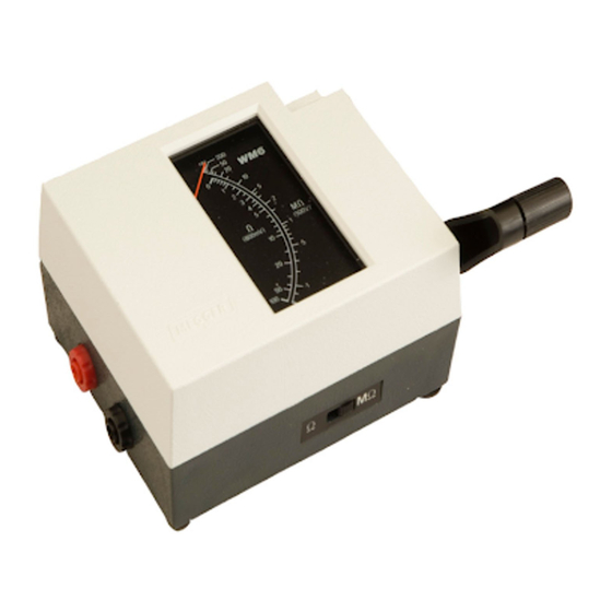
Note:— The cover of this instrument has been given voltage. an antistatic treatment which should be The WM6 uses a moving coil meter with taut band effective for many months. If in the course of suspension, white scales on a black scale plate and time the cover is found to retain electrostatic an orange ‘dayglow’... -
Page 5: Specification
SPECIFICATION ∞ Ranges insulation 0–200 MΩ and 0–100 Ω continuity Terminal Voltage insulation range <600 V on Open Circuit (d.c.) continuity range 800 mV approx. Terminal Voltage at insulation range 500 V + 10% –5% 1 M Load (d.c.) Terminal Current insulation range 1,3 mA approx. - Page 6 SPECIFICATION Fuse 20 x 5 mm ceramic Dimensions 131 x 98 x 61 mm (5 Weight 650 g (1 lb 7 oz) Terminal Voltage Characteristics Ω...
-
Page 7: Accessories
SPECIFICATION ACCESSORIES Illustrations of Typical Scales (full size) SUPPLIED WITH THE INSTRUMENT Test lead set including shrouded crocodile clips User Guide Part No. 6171-685 Test Record Card (5 supplied) Part No. 6172-111 AVAILABLE AS AN OPTIONAL EXTRA A leather ‘test-and-carry’ case with a special compartment for test leads Part No. -
Page 8: Operation
OPERATION W A R N I N G PRELIMINARY CHECKS 1 . The circuit under test m u s t be de-energized and Inspect the test leads to see that they have good isolated before insulation or continuity tests are unbroken insulation. -
Page 9: Fuse Replacement
∞ FUSE REPLACEMENT If several successive readings of ‘ ’ are obtained, connect the two further ends of the test leads together The fuse is held in a screw-type holder. To change a and turn the generator handle. A zero reading should fuse, use a screwdriver to release the centre part of result which double checks that the leads are not the holder containing the fuse. -
Page 10: Preventive Maintenance
Preventive Maintenance The proverb ‘A stitch in time saves nine’ inspired the title of an AVO International booklet on insulation testing, as it neatly sums up the benefits of preventative maintenance. The savings come in financial terms from costly repairs, lost production, lost profits and in human terms, from lives saved in the event of dangerous electrical faults. -
Page 11: Insulation Testing Concepts
Insulation Testing Concepts Absorption current. This current is also initially high but drops at a much slower rate than the charging Insulation resistance can be considered by applying c u r r e n t . Ohm’s Law. The measured resistance is determined from the applied voltage divided by the resultant current, Conduction or Leakage current. -
Page 12: Mode D'emploi
MODE D’EMPLOI A V E R T I S S E M E N T S placer sur le zéro de l’échelle. En cas d’indication de ∞ résistance de valeur élevée (ou position ‘ ’) les 1 ) Le circuit à essayer doit être mis hors tension et cordons sont peut-être coupés. - Page 13 ( a ) Pour les essais d’isolement par rapport à la terre ESSAIS DE CONTINUITE — Relier le cordon rouge à la terre ou au bâti de la Après avoir branché les cordons sur l’appareil, avoir structure en essai, et le cordon noir à la partie du vérifié...
-
Page 14: Auswechseln Der Sicherung
BETRIEBSANWEISUNG A C H T U N G ! Die Kabelklemmen bzw. Enden verbinden und die Generatorkurbel erneut drehen. Das Meßgerät soll nun 1 . Vor der Isolierungs-oder Durchgangsprüfung m u ß Null anzeigen. Liegt die Anzeige auf Unendlich oder die zu prüfende Schaltung entladen und von der bei einem hohen Widerstandswert, kann eine Stromquelle getrennt werden. - Page 15 PRÜFEN DER ISOLIERUNG Kapazitive Schaltungen entladen automatisch durch das Prüfgerät, wenn die Generatorkurbel nicht mehr Nach Anschließen der Testkabel an das Gerät und gedreht wird. Der Gerätzeiger geht über die Stellung Ausführen der oben genannten Vorprüfungen den ∞ ‘ ’ auf der Skale hinaus und kehrt dann zur normalen Schiebeschalter auf ‘MΩ’...
-
Page 16: Instrucciones De Uso
INSTRUCCIONES DE USO A D V E R T E N C I A la escala. Si esto no es asi, puede que estén averiadas las sondas de prueba, y deberán 1 . El circuito bajo prueba debe ser descargado y inspeccionarse mas detenidamente por si están aislado antes de efectuar las pruebas de dañadas. - Page 17 COMPROBACION DE AISLAMIENTO desconectadas o rotas y que por consiguiente son correctas las lecturas de aislamiento. Los circuitos Después de conectar las sondas de prueba en el capacitivos se descargan automaticamente a través instrumento y de efectuar las verificaciones indicadas del probado cuando se detiene el giro de la manivela previamente, seleccionar el interruptor deslizante en la del generador.
-
Page 18: Setting-Up Procedure
SETTING-UP PROCEDURE Notes on the basic setting-up procedure are given in the table below. See ‘Repair and Warranty’ notes o p p o s i t e . S t e p Adjustment potentiometer Adjustment for Conditions for adjustment R 1 5 scale 10 MΩ... -
Page 19: Repair And Warranty
REPAIR AND WARRANTY The instrument circuit contains static sensitive devices, Approved Repair Companies and care must be taken in handling the printed circuit A number of independent instrument repair board. If the protection of an instrument has been companies have been approved for repair work on most impaired it should not be used, and be sent for repair by M E G G E R ®... - Page 22 This instrument is manufactured in the United Kingdom. The company reserves the right to change the specification or design without prior notice. MEGGER is the registered Trade Mark of AVO INTERNATIONAL LIMITED. Copyright ©, AVO INTERNATIONAL LIMITED Part No 6171-685 Edition 6...