Evolution R210SMS Notice Originale

Masquer les pouces Voir aussi pour R210SMS:
Table des Matières

Publicité

Les langues disponibles
  • FR

Les langues disponibles

  • FRANÇAIS, page 100

Liens rapides

Original Instructions
Originalbetriebsanleitung
Instructions Originales
Instrucciones Originales
Notice Originale
Oryginalna Instrukcja
GB2438285
Original written in UK English
Date Published: 11/06/2018

Publicité

Table des Matières
loading

Sommaire des Matières pour Evolution R210SMS

  • Page 1 Original Instructions Originalbetriebsanleitung Instructions Originales Instrucciones Originales Notice Originale Oryginalna Instrukcja GB2438285 Original written in UK English Date Published: 11/06/2018...
  • Page 2 EMAIL: customer.services@evolutionpowertools.com WARRANTY Congratulations on your purchase (1.4) of an Evolution Power Tools Machine. Please complete your product registration ‘online’ as explained on the leaflet included with this machine. This will enable you to validate your machine’s warranty period via Evolution’s website by entering your details and thus ensure prompt service if ever needed.
  • Page 3: Machine Specifications

    R210SMS R210SMS+ MACHINE SPECIFICATION S MACHINE Motor (220-240V ~ 50 Hz) 1500W 1500W Motor (110V ~ 50 Hz) 1500W 1500W Speed No Load 3750 min 3750 min Weight (Net) 11.2kg 11.2kg Dust Port Diameter 36mm 36mm Tool Dimensions (H x W x L) (0° / 0°)
  • Page 4 R210SMS-300 R210SMS-300+ *Noise emission test according to EN 62841-1 & EN 62841-3-9. 1500W 1500W WARNING: The noise emissions during actual use of the power tool can differ from 1500W 1500W the declared values depending on the ways 3750 min...
  • Page 5: Intended Use Of This Power Tool

    Contact Evolution sliding mitre saw and has been designed Power Tools for replacement labels. to be used with genuine Evolution blades rated for this machine. Only use blades Note: All or some of the following symbols designed for use in this machine and/ may appear in the manual or on the product.
  • Page 6 www.evolutionpowertools.com SAFETY PRECAUTIONS 1. General Power Tool Safety Warnings (2.2) ELECTRICAL SAFETY [Work area safety] (1.14) a) Keep work area clean and well lit. This machine is fitted with the correct moulded Cluttered or dark areas invite accidents. plug and mains lead for the designated market. b) Do not operate power tools in explosive If the supply cord is damaged, it must be atmospheres, such as in the presence of...
  • Page 7 www.evolutionpowertools.com power tool. Do not use a power tool while does not turn it on or off. Any power tool you are tired or under the influence of that cannot be controlled with the switch is drugs, alcohol or medication. A moment dangerous and must be repaired.
  • Page 8 www.evolutionpowertools.com should only be removed by a professional d) Push the saw through the workpiece. and you should not attempt to remove Do not pull the saw through the workpiece. it yourself. To make a cut, raise the saw head and pull Once the dust has been deposited on it out over the workpiece without cutting, start the motor, press the saw head down and...
  • Page 9: Blade Safety

    Unstable support for the workpiece with the requirements of EN 847-1. can cause the blade to bind or the workpiece to • Only use genuine Evolution blades shift during the cutting operation pulling you rated for this machine. and the helper into the spinning blade.
  • Page 10 www.evolutionpowertools.com SAFE OPERATION PERFORM CUTS (3.7) (3.8) CORRECTLY & SAFELY Always ensure that you have selected the correct saw blade for the material being cut. Do not use Wherever practicable always secure the this mitre saw to cut materials other than those work-piece to the saw table using the work specified in this Instruction Manual.
  • Page 11 • Before moving the mitre saw tighten the the Evolution Power Tools helpline or go to: mitre and bevel locking screws and the www.evolutionpowertools.com sliding carriage locking screw to guard against sudden unexpected movement.
  • Page 12 ITEMS SUPPLIED (4.2) R210SMS R210SMS+ R210SMS-300 R210SMS-300+ 048-0001 048-0001A 048-0030 048-0030A Product Code 048-0002 048-0002A 048-0031 048-0031A 048-0003 048-0003A 048-0032 048-0032A 20 Tooth Blade 24 Tooth Blade 2 Pc Hold Down Clamp 3 Pc Hold Down Clamp Machine Table Extensions Dust Collection Bag Double Ended Hex Key (M6 &...
  • Page 13: Machine Overview

    MACHINE OVERVIEW Pictured: R210SMS (See ◊ for R210SMS+ and R210SMS-300+ Parts. See * for R210SMS+ Parts) 13. BLADE 1. CUTTING HANDLE 2. BLADE GUARD LOCKING TRIGGER 14. LOWER BLADE GUARD 3. DUST BAG ◊ 15. TABLE TOP 4. SLIDE LOCKING SCREW 16.
  • Page 14 Pictured: R210SMS (See ◊ for R210SMS+ and R210SMS-300+ Parts. See * for R210SMS+ Parts) 25. ON / OFF TRIGGER SWITCH 34. M4 SELF TAPPING CAP SCREW x1 26. LASER GUIDE ON / OFF SWITCH 35. M4 SOCKET HEAD SCREW x4 27.
  • Page 15 R210SMS R210SMS-300 Handle R210SMS+ R210SMS-300+ Handle Fig. 1 Fig. 2 Fig. 3 Fig. 4 Fig. 5 Fig. 6 Fig. 7 Fig. 8 Fig. 9 Fig. 10 Fig. 11 Fig. 12...
  • Page 16 CLICK Fig. 13a Fig. 13b Fig. 14a R210SMS-300 R210SMS-300+ Only Fig. 14b Fig. 14c Fig. 14d Fig. 15 Fig. 16 Fig. 17 Fig. 18 Fig. 19 Fig. 20...
  • Page 17 www.evolutionpowertools.com Fig. 21 Fig. 22 Fig. 23 Fig. 24 Fig. 25 Fig. 26 Fig. 27 Fig. 28a Fig. 28b Fig. 28c Fig. 29 Fig. 30...
  • Page 18 FIT LONG FIT LONG CLAMP CLAMP (R210SMS+) (R210SMS+) Fig. 31 Fig. 32 Fig. 33 Fig. 34 Fig. 35 Fig. 36 Fig. 37 Fig. 38 Fig. 39 Fig. 40 Fig. 41a Fig. 41b...
  • Page 19 3) Flat washer 4) Mitre saw base 5) Workbench 6) Flat washer 7) Spring washer 8) Hex nut 9) Lock nut Fig. 42 Fig. 43 R210SMS R210SMS+ R210SMS-300 R210SMS-300+ 2pc Clamp 3pc Clamp Fig. 45 Fig. 46 Fig. 44 Danger...
  • Page 20 www.evolutionpowertools.com Fig. 53 Fig. 54 Fig. 55 Fig. 57 Fig. 58 Fig. 56 Fig. 60 Fig. 61 Fig. 59 Fig. 62 Fig. 63 Fig. 64...
  • Page 21 www.evolutionpowertools.com ASSEMBLY AND PREPARATION WARNING: Do not under any circumstances (7.1) plug the cutting head into the power supply WARNING: Always disconnect the saw and try to use it as a hand held circular saw. from the power source before making any adjustments.
  • Page 22 Note: Two (2) machine table extension pieces The carriage slide should be inserted from the are provided with this machine. They are back ensuring that the ‘Evolution’ logo is the ‘handed’ , one being for the right hand side, correct way up. (Fig. 9) and one for the left hand side.
  • Page 23: Unlatching And Raising The Cutting Head

    (included). (Fig. 20) Evolution Power Tools and which are designed Note: The cable should not be tight anywhere for this machine. Ensure that the maximum along its length. (Fig. 21) speed of the blade is higher than the speed of the motor.
  • Page 24: The Depth Stop

    www.evolutionpowertools.com • Ensure the Hex Key is removed and the blade is set exactly perpendicular to the table arbor lock has released before proceeding. when in the upright position and against its stop. • Ensure the blade guard is fully functional before using the machine.
  • Page 25: The Sliding Upper Fence Section

    The Rotary table • Repairs to the laser module must only be must be set at ‘0˚’ mitre angle. conducted by Evolution Power Tools or their authorized agent. The Fence is fastened to the table with three (3) socket head Hex screws (Fig.
  • Page 26: Laser Safety

    www.evolutionpowertools.com LASER SAFETY and forwards along the fence, whilst at the same time slowly adjusting the angle of the The laser guide line used in this product uses rotary table. a class 2 laser with a maximum power output • Stop when the projected laser line and pencil of 1mW at a wave length of between 650nm.
  • Page 27: Permanently Mounting The Mitre Saw

    Note: The R210SMS includes the 2 piece clamp. • Support the saw so the machine table is level The R210SMS+ includes 3 piece clamp.
  • Page 28: Body & Hand Positioning

    www.evolutionpowertools.com WARNING: Ensure that the operator is WARNING: Freehand cutting is a major cause adequately trained in the use, adjustment of accidents and should not be attempted. and maintenance of this machine, before • Ensure that the work-piece is always firmly connecting it to the power supply and resting against the fence, and where practical commencing operations.
  • Page 29: Mitre Cutting

    www.evolutionpowertools.com release the slide and allow the cutting head to • Loosen the mitre handle locking knob (Fig. 56) move forwards and backwards. (Fig. 52) by turning the locking knob anti-clockwise. The saw blade is lowered into the work-piece • Pull up the positive stop locking lever. (Fig. 57) and then pushed to the rear of the machine to •...
  • Page 30: Compound Cutting

    ACCESSORIES This machine is capable of cutting the mitre angles required for Crown Mouldings. To DUST BAG (Supplied with R210SMS+) configure the machine to cut Crown Moulding: A Dust Bag can be fitted to the extraction port • Deploy the 33.9˚ Bevel Pin by pushing it fully at the rear of the machine.
  • Page 31 www.evolutionpowertools.com MAINTENANCE Note: Any maintenance must be carried out with the machine switched off and disconnected from the mains/battery power supply. Check that all safety features and guards operating correctly on a regular basis. Only use this machine if all guards/safety features are fully operational.
  • Page 32: Assembly Safety Checks

    www.evolutionpowertools.com ASSEMBLY SAFETY CHECKS PART CONDITION Slides Inserted through the bevel neck and connected to the cutting head. Locating lugs successfully deployed. Mitre Handle Locking Knob Installed into mitre handle / rotary table Slide Carriage Inserted into the threaded hole in the bevel neck. Anti-vibration locking screw spring fitted beneath the locking screw hand knob.
  • Page 33: Ec Declaration Of Conformity

    EC DECLARATION OF CONFORMITY The manufacturer of the product covered by this Declaration is: UK: Evolution Power Tools Ltd, Venture One, Longacre Close, Holbrook Industrial Estate, Sheffield, S20 3FR FR: Evolution Power Tools SAS, 61 Avenue Lafontaine, 33560, Carbon-Blanc, Bordeaux, France.
  • Page 34: Garantie

    Systems über die Website von Evolution zu überprüfen, indem Sie Ihre Daten eingeben und so einen schnellen Service bei Bedarf erhalten können. Wir bedanken uns bei Ihnen herzlich, dass Sie sich für ein Produkt von Evolution Power Tools entschieden haben.
  • Page 35 MASCHINENSPEZIFIKATIONEN R210SMS R210SMS+ MACHINE Motor (220-240V ~ 50 Hz) 1500W 1500W Motor (110V ~ 50 Hz) 1500W 1500W Geschwindigkeit ohne Ladung 3750 min 3750 min Gewicht (Netto) 11.2kg 11.2kg Durchmesser Absaugvorrichtung 36mm 36mm Werkzeugabmessungen(H x W x L) (0° / 0°)
  • Page 36 R210SMS-300 R210SMS-300+ Die angegebenen Geräuschemissionswerte sind nach einem genormten Prüfverfahren gemessen worden und können zum Vergleich 1500W 1500W eines Elektrowerkzeugs mit einem anderen verwendet werden; 1500W 1500W 3750 min 3750 min Die angegebenen Geräuschemissionswerte 13.2kg 13.2kg können auch zu einer vorläufigen...
  • Page 37: Beschreibung

    Verwenden Sie nur Klingen, die für den Einsatz Power Tools für Ersatzkennzeichen. in dieser Maschine und/oder die speziell von Evolution Power Tools Ltd. empfohlen wurden. Hinweis: Alle oder einige der folgenden Symbole können im Handbuch oder auf dem Produkt WENN MIT EINER KORREKTEN erscheinen.
  • Page 38 www.evolutionpowertools.com SICHERHEITSVORKEHRUNGEN BEWAHREN SIE ALLE ELEKTRISCHE SICHERHEIT SICHERHEITSHINWEISE UND (1.14) ANWEISUNGEN FÜR DIE ZUKUNFT Diese Maschine ist mit dem richtig geformten AUF. Stecker und Netzkabel für den dafür vorgesehenen Markt ausgestattet. Wenn das Der in den Sicherheitshinweisen verwendete Netzkabel beschädigt ist, muss es durch ein Begriff „Elektrowerkzeug“...
  • Page 39 www.evolutionpowertools.com Sie jederzeit auf einen richtigen Stand Freien verwenden Sie ein Verlängerungskabel, und Balance. Dies ermöglicht eine bessere das für den Einsatz im Außenbereich geeignet ist. Die Verwendung eines für den Einsatz im Kontrolle des Elektrowerkzeugs in unerwarteten Außenbereich geeigneten Kabels verringert das Situationen.
  • Page 40 www.evolutionpowertools.com auf und lassen Sie Personen, die mit hat, kann es über Hand-zu-Mund-Kontakt zu dem Elektrowerkzeug oder diesen einer Einnahme von Blei führen. Die Exposition Anweisungen nicht vertraut sind, nicht gegenüber bereits wenig Blei kann zu dieses Elektrowerkzeug verwenden. irreversiblen Hirn- und Nervensystemschäden Elektrowerkzeuge sind gefährlich in den Händen führen.
  • Page 41 www.evolutionpowertools.com Weise. Unbehinderte oder bewegte Werkstücke montiert oder auf einer ebenen, festen Arbeitsfläche platziert ist, bevor Sie es könnten mit hohen Geschwindigkeiten geworfen werden, was zu Verletzungen führt. benutzen. Eine ebene und feste Arbeitsfläche d) Schieben Sie die Säge durch das Werkstück. reduziert das Risiko, dass die Gehrungssäge Nicht die Säge durch das Werkstück ziehen.
  • Page 42: Persönliche Schutzausrüstung (Psa)

    Werkstück kann zu einem wie in diesem Handbuch beschrieben und die Kontrollverlust oder einer Beschädigung der Anforderungen der EN 847-1 erfüllen. • Verwenden Sie nur original Evolution Gehrungssäge führen. r) Nach Beendigung des Schnittes den Schalter Klingen, welche für diese Maschine geeignet sind.
  • Page 43 www.evolutionpowertools.com SCHNITTE KORREKT & SICHER Schiebesäge-Säge sicherstellen, dass die (3.8) DURCHFÜHREN Schiebebügel verriegelt sind). Heben Sie die Maschine an, indem Sie die Außenkanten des Wo immer es praktisch ist, immer das Werkstück Sockels mit beiden Händen ergreifen (bei einer an den Sägetisch mit der Arbeitsklammer, wo Gehrungssäge, transportieren Sie über den vorgesehen, sichern.
  • Page 44 Verschlussschraube des zum Identifizieren des Chargencodes Schiebewagens festziehen, um vor einer wenden Sie sich bitte an das Evolution Power plötzlich unerwarteten Bewegung zu schützen. Tools Hilfecenter oder gehen Sie auf :www. • Den Schneidkopf in seiner untersten Position evolutionpowertools.com...
  • Page 45 LIEFERUMFANG (4.2) R210SMS R210SMS+ R210SMS-300 R210SMS-300+ 048-0001 048-0001A 048-0030 048-0030A Produkt-Code 048-0002 048-0002A 048-0031 048-0031A 048-0003 048-0003A 048-0032 048-0032A 20 Zahnklinge 24 Zahnklinge Niederhalter MMaschinentisch Erweiterungen Staubsammelbeutel Doppelte Sechskantschlüssel (M6 & M4) Bedienungsanleitung (Montage & Betrieb) Rundtisch und Hals...
  • Page 46 MASCHINENÜBERSICHT Im Bild: R210SMS (Siehe◊ für R210SMS + und R210SMS=300 Teile. Siehe * für R210SMS + Teile) 1. HANDGRIFF 13. KLINGE 2. ENTRIEGELUNGSHEBEL 14. UNTERER KLINGENSCHUTZ 3. STAUBBEUTEL* 15. TISCHPLATTE 4. SCHIEBE-VERRIEGELUNGSSCHRAUBE 16. DREHTISCH 5. TIEFENMESSER 17. TISCHEINSATZ 6. NIEDERHALTER 18.
  • Page 47 Im Bild: R210SMS (Siehe◊ für R210SMS + und R210SMS=300 Teile. Siehe * für R210SMS + Teile) 25. EIN-/AUS-AUSLÖSESCHALTER 34. M4 SELBSTSCHNEIDENDE ZYLINDERSCHRAUBE x1 26. EIN-/AUS-SCHALTER DER LASERFÜHRUNG 35. M4 SELBSTSCHNEIDENDE 27. ENTSTAUBUNGSANSCHLUSS ZYLINDERSCHRAUBE x1 28. KABEL 36. KABELZUGENTLASTUNG 29. SCHNEIDKOPF SICHERUNGSSTIFT (FÜR KABELFÜHRUNGSKLEMME)
  • Page 48 R210SMS R210SMS-300 Handle R210SMS+ R210SMS-300 Handle Abb. 1 Abb. 2 Abb. 3 Abb. 4 Abb. 5 Abb. 6 Abb. 7 Abb. 8 Abb. 9 Abb. 10 Abb. 11 Abb. 12...
  • Page 49 KLICKEN Abb. 13a Abb. 13b Abb. 14a R210SMS-300 R210SMS-300+ Only Fig. 14b Fig. 14c Fig. 14d Fig. 15 Fig. 16 Fig. 17 Abb. 18 Abb. 19 Abb. 20...
  • Page 50 www.evolutionpowertools.com Abb. 21 Abb. 22 Abb. 23 Abb. 24 Abb. 25 Abb. 26 Abb. 27 Abb. 28a Abb. 28b Abb. 28c Abb. 29 Abb. 30...
  • Page 51 PASSEN SIE LANGE PASSEN SIE LANGE KLAMMER AN KLAMMER AN (R210SMS+) (R210SMS+) Abb. 31 Abb. 32 Abb. 33 Abb. 34 Abb. 35 Abb. 36 Abb. 37 Abb. 38 Abb. 39 Abb. 40 Abb. 41a Abb. 41b...
  • Page 52 1) Sechskantschraube 2) Federscheibe 3) Unterlegscheibe 4) Gehrungssägenbasis 5) Werkbank 6) Unterlegscheibe 7) Federscheibe 8) Sechskantmutter 9) Kontermutter Abb. 42 Abb. 43 R210SMS R210SMS+ R210SMS-300 R210SMS-300+ 2pc Clamp 3pc Clamp Abb. 45 Abb. 46 Abb. 44 Gefahren Zone No-Hands Zone Abb.47...
  • Page 53 www.evolutionpowertools.com Abb. 53 Abb. 54 Abb. 55 Abb. 57 Abb. 58 Abb. 56 Abb. 60 Abb. 61 Abb. 59 Abb. 62 Abb. 63 Abb. 64...
  • Page 54 www.evolutionpowertools.com MONTAGE UND VORBEREITUNG Stromversorgung und versuchen Sie es, als (7.1) Handkreissäge zu verwenden. WARNUNG: Trennen Sie die Säge immer von der Stromquelle, bevor Sie Einstellungen vornehmen. KENNEN SIE DIE TEILE Für die Inbetriebnahme dieser Maschine ist eine Es sind vier (4) Hauptteile zu montieren kleinere Montage erforderlich.
  • Page 55 (Modelle R210SMS-300 und R210SMS-300+) WAGENSCHLITTEN EINFÜGEN WICHTIGER HINWEIS: Wenn aus irgendeinem Zwei zusätzliche Schrauben werden mitgeliefert, Grund (Transportschaden, Fehler beim Auspacken, die dort in den Kopf der Säge geschraubt Bedienerfehler usw.) die Rastnasen an der Spitze werden sollten, wo er auf die hinteren der Wagenschieberarme „ausgelöst“...
  • Page 56 Sie auch den Schlitten. Evolution Klingen oder solche Klingen, Vergewissern Sie sich, dass sich das Kabel nicht die speziell von Evolution Power Tools mit anderen Teilen der Maschine verheddert. empfohlen werden und die für diese Maschine Vergewissern Sie sich auch, dass das Kabel konzipiert sind.
  • Page 57 Kante gegen die Klinge (vermeiden Sie die TCT- Spitzen). (Abb. 24) WARNUNG: Zur sicheren Installation der Evolution Mehrzweckklingen muss der innere • Wenn sich die Klinge nicht im 90 Grad (Winkel) Messerflansch mit dem nach außen weisenden mit dem Drehtisch befindet, dann ist eventuell 25,4 mm Naben montiert werden.
  • Page 58: Der Gleitende Obere Anschlagbereich

    www.evolutionpowertools.com 45˚ Abschrägungsstopp-Einstellung • Sobald die gewünschte Tiefe eingestellt ist, ziehen Sie die Rändelmutter (Abb.28b) gegen • Lösen Sie die Absperreinheit der Abschrägung und neigen Sie den Schneidekopf die Halteklammer fest, um den Tiefenstopp zu ganz nach links, bis er sich in der 45˚ versperren und sicherzustellen, dass es keine Stoppposition befindet.
  • Page 59: Der Laser

    Verriegelungsstift vollständig eingerastet ist. • Reparaturen an dem Lasermodul dürfen nur von • Legen Sie ein Zeichendreieck auf den Tisch mit Evolution Power Tools oder deren beauftragten einer Kante gegen den Anschlag und die andere Techniker durchgeführt werden. Kante gegen die Klinge (Vermeiden Sie die TCT- Spitzen).
  • Page 60 www.evolutionpowertools.com oder dem Positiven Anschlagsverschlusshebel • Mit dem Schlitten in der hintersten Position einrasten lassen. senken Sie den Schneidekopf ab, so dass ein • Schalten Sie den Laserstrahl ein. Klingenzahn eine Markierung im • Positionieren Sie das Werkstück auf den Karton hinterlässt.
  • Page 61: Für Tragbare Verwendung

    Werkbank. Stellen Sie sicher, dass der Niederhalter den Weg der Klinge nicht beeinträchtigt, oder mit dem Weg Hinweis: Diese Maschine kann an der Evolution eines anderen Teils des Schneidekopfes kommt, da Gehrungssägenständer befestigt werden dieser abgesenkt wird, um den Schnitt (Abb.
  • Page 62 www.evolutionpowertools.com nicht versucht werden. Stromversorgung anschließen und den Betrieb starten. Um das Verletzungsrisiko zu • Stellen Sie sicher, dass sich das Werkstück immer verringern, trennen Sie immer die Maschine fest gegen den Anschlag befindet und wo vom Strom, bevor Sie die Maschinenteile praktisch mit dem Niederhalter auf den Tisch wechseln oder einstellen.
  • Page 63 www.evolutionpowertools.com • Entfernen Sie das Werkstück. Gleitschnitt durchgeführt wird. Wenn der Schneidekopf in der richtigen Position über GLEITSCHNITT dem Werkstück ist, kann er abgesenkt und Diese Säge ist mit einem Schlittensystem nach hinten in Richtung Anschlag geschoben ausgestattet. werden, um den Schnitt zu vervollständigen. Durch das Lösen der Verriegelungsschraube wird die Schiene gelöst und der Schneidekopf kann GEHRUNGSSCHNITT (Abb.
  • Page 64: Schneiden Von Bogenförmigen Material

    www.evolutionpowertools.com der entfalteten (herausgezogenen) der Absperreinheit der Abschrägung. Position bleiben. • Drehen Sie den Drehtisch und stellen Sie den Gehrungswinkel auf 31,6 ° ein, wie auf der Um den Schneidkopf nach links zu kippen: Winkelmesser-Skala angezeigt. • Lösen Sie die Absperreinheit der Abschrägung. (Abb.
  • Page 65 OPTIONALES EVOLUTION ZUBEHÖR ordnungsgemäß funktionieren. Verwenden STAUBBEUTEL Sie diese Maschine nur, wenn alle Ein Staubbeutel kann an der Absaugöffnung an Schutzeinrichtungen/Sicherheitsfunktionen voll der Rückseite des Gerätes angebracht werden. funktionsfähig sind. Der Staubbeutel ist nur zum Schneiden von Holzwerkstoffen geeignet.
  • Page 66: Sicherheitskontrollen Während Der Montage

    www.evolutionpowertools.com SICHERHEITSKONTROLLEN WÄHREND DER MONTAGE TEIL KONDITION Eingefügt durch den Kegelhals und verbunden mit dem Gleitschienen Schneidkopf. Lokalisierungslaschen erfolgreich eingesetzt. Feststellknopf des Installiert in Gehrungsgriff/Drehtisch Gehrungsgriffes Schlittenwagen Eingefügt in das Gewindeloch des Kegelhalses. Anti-Vibrationsfeder Verriegelungsschraube unterhalb der Verriegelungsschraube des Handknopfes eingebaut. Entsprechend verkabelt mit korrekt montierter Kabelführung/ Stromkabel Klemmen.
  • Page 67: Eg-Konformitätserklärung

    EG-KONFORMITÄTSERKLÄRUNG Der Hersteller des unter diese Erklärung fallendem Produktes lautet: UK: Evolution Power Tools Ltd, Venture One, Longacre Close, Holbrook Industrial Estate, Sheffield, S20 3FR FR: Evolution Power Tools SAS, 61 Avenue Lafontaine, 33560, Carbon-Blanc, Bordeaux, France. Der Hersteller erklärt hiermit, dass die in dieser Erklärung genannte Maschine alle einschlägigen Bestimmungen der Maschinenrichtlinie und andere geeignete Richtlinien, wie nachfolgend beschrieben, erfüllt.
  • Page 68 Esto le permitirá validar el periodo de garantía de su máquina a través de la página web de Evolution al introducir sus datos y, así, disponer de un servicio rápido si fuera necesario. Le estamos sinceramente agradecidos por escoger uno de nuestros productos Evolution Power Tools.
  • Page 69: Características Técnicas De La Máquina

    www.evolutionpowertools.com CARACTERÍSTICAS TÉCNICAS DE LA MÁQUINA MÁQUINA MÉTRICO IMPERIAL Motor (220-240 V ~ 50 Hz) 1500 W 7 A Velocidad sin carga 3750 min 3750 rpm Peso (neto) 11,2 kg 25 lb Diámetro del puerto de polvo 36 mm 1-27/64” Dimensiones de la herramienta (Al x An x L) (0° / 0°) 12-23/64 x 314 x 575 x 610 mm 22-41/64 x 24-1/64”...
  • Page 70: Uso Previsto De Esta Herramienta Eléctrica

    Póngase en contacto con Evolution que hayan sido diseñadas para esta Evolution Power Tools para sustituir máquina. Use solo hojas diseñadas para el uso las etiquetas.
  • Page 71 www.evolutionpowertools.com USO EN EXTERIORES b) No utilice las herramientas eléctricas en (1.15) atmósferas explosivas, como en presencia ADVERTENCIA: para su protección, si va a de líquidos inflamables, gases o polvo. Las usar esta herramienta en exteriores no debe herramientas eléctricas producen chispas que exponerla a la lluvia o usarla en lugares pueden incendiar el polvo o los gases.
  • Page 72 www.evolutionpowertools.com herramienta eléctrica cuando esté cansado Las herramientas eléctricas que no se puedan o bajo la influencia de drogas, alcohol o controlar con el interruptor son peligrosas y se medicación. Un momento de distracción deben reparar. mientras utiliza herramientas eléctricas puede c) Desconecte la herramienta eléctrica de la fuente de alimentación y/o el paquete de ocasionar lesiones personales graves.
  • Page 73 www.evolutionpowertools.com CONSEJOS PARA SU SALUD fijadas podrían ser arrojadas a altas velocidades, (2.7) provocando lesiones. ADVERTENCIA: Si sospecha que la pintura en d) Empuje la sierra a través de la pieza de las superficies de su hogar contiene plomo, trabajo. No tire de la sierra a través de la pieza busque consejo profesional.
  • Page 74: Seguridad De La Hoja

    EN 847-1. de usted y del ayudante hacia a la hoja giratoria. • Utilice solo hojas Evolution originales diseñadas n) La pieza cortada no se debe atascar ni para esta máquina.
  • Page 75: Advertencias De Seguridad

    www.evolutionpowertools.com resistentes al calor al manejar materiales metálicos láser no funciona, será reparado o sustituido por el que puedan estar calientes. Se recomienda que fabricante o agente autorizado. las hojas de sierra se lleven en un soporte siempre La hoja de la sierra solo se puede sustituir como se que sea factible.
  • Page 76: De Serie / Código De Lote

    • Bloquee la cabeza de corte en su posición el código de lote, póngase en contacto con el más baja. Asegúrese de que el seguro de la teléfono de asistencia de Evolution Power Tools o cabeza de corte esté completamente insertado visite: www.evolutionpowertools.com en su cavidad.
  • Page 77 ELEMENTOS SUMINISTRADOS (4.2) R210SMS R210SMS+ 048-0001 048-0001A Código de producto 048-0002 048-0002A 048-0003 048-0003A Hoja de 20 dientes Hoja de 24 dientes Mordaza de sujeción de 2 piezas Mordaza de sujeción de 3 piezas Extensiones de mesa de la máquina Saco captapolvo Llave hexagonal de doble extremo (M6 &...
  • Page 78: Descripción General De La Máquina

    DESCRIPCIÓN GENERAL DE LA MÁQUINA Ilustrado: R210SMS (véase * para R210SMS+ piezas) 1. MANGO DE CORTE 12. CABEZA DE CORTE 2. GATILLO DE BLOQUEO DE LA PROTECCIÓN DE 13. HOJA LA HOJA 14. PROTECCIÓN INFERIOR DE LA HOJA 3. SACO CAPTAPOLVO* 15.
  • Page 79 Ilustrado: R210SMS 25. GATILLO INTERRUPTOR ON / OFF 34. TORNILLO DE CABEZA AUTORROSCANTE M4 x1 26. INTERRUPTOR ON / OFF DE LA GUÍA LÁSER 35. TORNILLO DE CABEZA HUECA M4 x4 27. PUERTO DE EXTRACCIÓN DE POLVO 36. COMPONENTE DE SUJECIÓN DEL CABLE (EQUIPADO EN LA MORDAZA DE LA GUÍA DEL...
  • Page 80 R210SMS Mango R210SMS+ Mango Fig. 1 Fig. 2 Fig. 3 Fig. 4 Fig. 5 Fig. 6 Fig. 7 Fig. 8 Fig. 9 Fig. 10 Fig. 11 Fig. 12...
  • Page 81 www.evolutionpowertools.com CLIC Fig. 13a Fig. 13b Fig. 14a Fig. 14b Fig. 14c Fig. 15 Fig. 16 Fig. 17 Fig. 18 Fig. 19 Fig. 20...
  • Page 82 www.evolutionpowertools.com Fig. 21 Fig. 22 Fig. 23 Fig. 24 Fig. 25 Fig. 26 Fig. 27 Fig. 28a Fig. 28b Fig. 28c Fig. 29 Fig. 30...
  • Page 83 AJUSTE LARGO AJUSTE LARGO MORDAZA MORDAZA (R210SMS+) (R210SMS+) Fig. 31 Fig. 32 Fig. 33 Fig. 34 Fig. 35 Fig. 36 Fig. 37 Fig. 38 Fig. 39 Fig. 40 Fig. 41a Fig. 41b...
  • Page 84 4) Base de la sierra ingletadora 5) Banco de trabajo 6) Arandela plana 7) Arandela elástica 8) Tuerca hexagonal 9) Tuerca de seguridad Fig. 42 Fig. 43 R210SMS R210SMS+ Mordaza de 2 Mordaza de 3 piezas piezas Fig. 45 Fig. 46 Fig.
  • Page 85 www.evolutionpowertools.com Fig. 53 Fig. 54 Fig. 55 Fig. 57 Fig. 58 Fig. 56 Fig. 60 Fig. 61 Fig. 59 Fig. 62 Fig. 63 Fig. 64...
  • Page 86 www.evolutionpowertools.com MONTAJE Y PREPARACIÓN ADVERTENCIA: No conecte bajo ninguna (7.1) circunstancia la cabeza de corte al suministro ADVERTENCIA: desconecte siempre la de corriente ni intente usarla como sierra sierra de la alimentación antes de realizar circular de mano. ningún ajuste. Se requiere algo de montaje para la puesta en servicio de esta máquina.
  • Page 87 La corredera de la carretilla se debe insertar desde Nota: con esta máquina se proporcionan dos (2) atrás, asegurando que el logotipo de «Evolution» esté en posición correcta hacia arriba. (Fig. 9) piezas de extensión de la mesa de la máquina. Son •...
  • Page 88: Instalar O Desmontar Una Hoja

    Suba y baje la cabeza de corte varias veces y ADVERTENCIA: utilice únicamente hojas Evolution auténticas o aquellas hojas maneje también la carretilla corrediza. Compruebe que el cable no se enreda con ninguna otra recomendadas específicamente por Evolution Power Tools y que se hayan diseñado para...
  • Page 89 (evitando las puntas de TCT). (Fig. 24) ADVERTENCIA: para instalar las hojas Si la hoja no está a 90° (perpendicular) respecto multiusos Evolution, el borde interior de la hoja a mesa giratoria, entonces quizás se requiera un debe estar instalado con el buje de 25,4 mm ajuste.
  • Page 90: La Sección Superior De Valla Deslizable

    www.evolutionpowertools.com Nota: para evitar que la sección superior deslizable • Incline la cabeza de corte al ajuste de 45° y se retire completamente (y por tanto se pueda vuelva a comprobar la alineación con la escuadra. perder), la sección superior deslizable está «fijada» a la valla inferior.
  • Page 91: Seguridad Del Láser

    • Fije la pieza de trabajo en posición usando la • Las reparaciones en el módulo láser solo deben mordaza de sujeción. ser realizadas por Evolution Power Tools o su • Proceda a realizar el corte. agente autorizado. Para usar la guía láser para un ángulo Nota: la guía láser puede ser un dispositivo muy...
  • Page 92: Ajuste Del Láser

    • Vuelva a comprobar la alineación. Nota: esta máquina se puede unir al soporte B. Si el rayo láser está paralelo a las marcas, pero de sierra ingletadora Evolution. (Fig. 44). Esto no las atraviesa: proporcionará un soporte de taller seguro y •...
  • Page 93: Para El Uso Portátil

    ON/OFF y la hoja se haya detenido completamente. Nota: La R210SMS incluye la mordaza de 2 piezas. La R210SMS+ incluye la mordaza de 3 piezas. EL GATILLO INTERRUPTOR ON/OFF (Fig. 48)
  • Page 94: Corte De Tronzado

    www.evolutionpowertools.com Coloque la sierra en una superficie de trabajo • Baje el mango de corte hacia abajo y corte a estacionaria y segura, y compruebe la sierra través de la pieza de trabajo. minuciosamente. • Permita que la velocidad de la hoja haga el trabajo.
  • Page 95: Corte De Moldura De Techo

    www.evolutionpowertools.com la hoja y con la cabeza de corte bloqueada en La cabeza de corte se puede inclinar desde la posición normal de 0° (posición perpendicular) la posición superior antes de liberar el mango de corte. hasta un ángulo máximo de 45° desde la perpendicular solo al lado izquierdo.
  • Page 96 ACCESORIOS OPCIONALES DE EVOLUTION empujándolo completamente hacia dentro. (Fig. 59) SACO CAPTAPOLVO (suministrado con R210SMS+) • Incline la cabeza de corte a la posición de 33,9˚ Se puede instalar un saco captapolvo en el puerto y bloquéela en posición apretando el mango de bloqueo del bisel.
  • Page 97 www.evolutionpowertools.com Use un paño limpio y ligeramente húmedo para limpiar las piezas de plástico de la máquina. No utilice disolventes ni productos similares que podrían dañarlas. ADVERTENCIA: no intente limpiar introduciendo objetos puntiagudos a través de las aberturas de las cubiertas de las máquinas, etc.
  • Page 98: Comprobaciones De Seguridad Finales

    www.evolutionpowertools.com COMPROBACIONES DE SEGURIDAD DEL MONTAJE PIEZA ESTADO SÍ Correderas Instaladas a través del cuello del bisel y conectadas a la cabeza de corte. Asas de ubicación desplegadas correctamente. Botón de bloqueo del Instalado en el mango del inglete / mesa giratoria mango del inglete Tornillo de bloqueo Insertado en el orificio roscado en el cuello del bisel.
  • Page 99: Declaración De Conformidad De La Ce

    DECLARACIÓN DE CONFORMIDAD DE LA CE El fabricante del producto cubierto por esta declaración es el siguiente: UK: Evolution Power Tools Ltd, Venture One, Longacre Close, Holbrook Industrial Estate, Sheffield, S20 3FR FR: Evolution Power Tools SAS, 61 Avenue Lafontaine, 33560, Carbon-Blanc, Bordeaux, France.
  • Page 100 Cela vous permettra de valider la période de garantie de la machine via le site Internet d’Evolution en saisissant vos coordonnées, et garantir ainsi un service rapide si nécessaire. Nous vous remercions sincèrement d’avoir choisi un produit d’Evolution Power Tools.
  • Page 101: Spécifications De La Machine

    SPÉCIFICATIONS DE LA MACHINE R210SMS R210SMS MACHINE Moteur (220-240 V ~ 50 Hz) 1 500 W 1 500 W Vitesse à vide 3 750 min 3 750 min Poids (net) 11,2 kg 11,2 kg Diamètre du port à poussières 36 mm 36 mm Dimensions de l'outil (H x l x L) (0°/0°) 314 x 575 x 610 mm...
  • Page 102 R210SMS-300 R210SMS-300+ *Essai d’émission sonore conforme aux normes EN 62841-1 et EN 62841-3-9. 1500 W 1500 W AVERTISSEMENT: Les émissions sonores 3750 min 3750 min produites pendant l’utilisation de l’outil électrique peuvent être différentes des 13,2 kg 13,2 kg valeurs déclarées, en fonction de la manière...
  • Page 103: (1.8) Étiquettes Et Symboles De Sécurité

    AVERTISSEMENT : Ce produit est une scie à machine s’il manque des étiquettes onglets coulissante multi-matériaux conçue d’avertissement et/ou d’instruction ou si ces pour fonctionner avec des lames Evolution étiquettes sont endommagées. authentiques ayant été testées pour cette Contactez Evolution Power Tools pour le machine.
  • Page 104: (1.15) Utilisation En Extérieur

    www.evolutionpowertools.com MESURES DE SÉCURITÉ CONSERVEZ TOUS LES SÉCURITÉ ÉLECTRIQUE AVERTISSEMENTS DE SÉCURITÉ ET (1.14) TOUTES LES INSTRUCTIONS POUR Cette machine est équipée de la fiche moulée FUTURE RÉFÉRENCE. et du câble électrique adéquats pour le marché désigné. Si le cordon d’alimentation Le terme «...
  • Page 105 www.evolutionpowertools.com la chaleur, de l’huile, d'objets tranchants et e) Ne travaillez pas hors de portée. Gardez des pièces en mouvement. un bon appui et un bon équilibre à tout moment. Ceci permettra de mieux contrôler Un cordon endommagé ou emmêlé accroît le risque de choc électrique.
  • Page 106: (2.7) Conseils De Santé

    www.evolutionpowertools.com risque d’affecter le bon fonctionnement de Les jeunes enfants et les enfants à naître sont l’outil. En cas de dommages, faites réparer particulièrement vulnérables. l’outil avant de l’utiliser de nouveau. Beaucoup d’accidents sont causés par des outils AVERTISSEMENT : Certains produits en (2.8) bois ou dérivés du bois, surtout les MDF électriques mal entretenus.
  • Page 107 www.evolutionpowertools.com que ce soit. Les pièces à usiner non maintenues en toute sécurité et la lame risquerait de se ou mobiles risquent d’être projetées à grande bloquer ou de bouger lors de la découpe. j) Assurez-vous que la scie à onglets est vitesse et d’entraîner des blessures.
  • Page 108: Sécurité De La Lame

    à onglets coulissante, assurez-vous que les 847-1. barres coulissantes sont verrouillées). Soulevez • N'utilisez que des lames Evolution adaptées à la machine en attrapant les côtés extérieurs cette machine. de la base à deux mains (s’il s’agit d'une scie à...
  • Page 109: (3.8) Réaliser Des Découpes Correctement Et En Toute Sécurité

    www.evolutionpowertools.com poignées fournies). Vous ne devez en aucun cas c’est possible. soulever la machine ou la transporter à l’aide Avant chaque utilisation, vérifiez que la scie à du carter rétractable ou toute autre pièce du onglets est montée dans une position stable. mécanisme de fonctionnement.
  • Page 110: N° De Série : / Numéro De Lot

    • Desserrez la vis de blocage de l’angle de cette machine, vous trouverez les accessoires l'onglet. Faites pivoter la table vers l’une de suivants dans la boutique en ligne d’Evolution ses configurations maximales. sur www.evolutionpowertools.com ou chez • Verrouillez la table en utilisant la vis votre revendeur local.
  • Page 111 ARTICLES FOURNIS (4.2) R210SMS R210SMS+ 048-0001 048-0001A 048-0030 048-0030A Code produit 048-0002 048-0002A 048-0031 048-0031A 048-0003 048-0003A 048-0032 048-0032A Lame 20 dents Lame 24 dents Pince de verrouillage 2 éléments Pince de verrouillage 3 éléments Extensions de la table de la machine Sac de collecte de poussière...
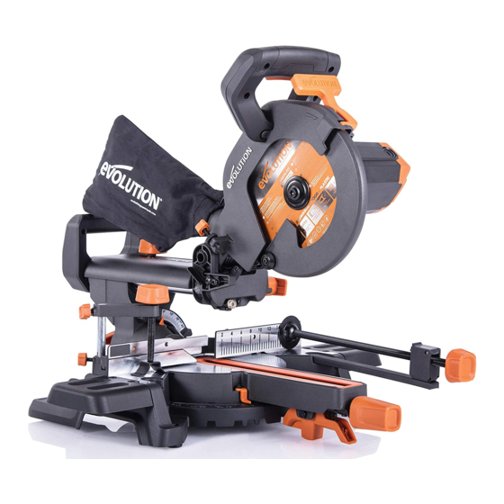
  • Page 112: Présentation De La Machine

    PRÉSENTATION DE LA MACHINE Modèle représenté : R210SMS (Se référer aux pièces suivies d’un ◊ pour les pièces du R210SMS+ et R210SMS-300+. Se référer aux pièces suivies d’un * pour les pièces du R210SMS.+) 1. POIGNÉE DE DÉCOUPE 13. LAME 2.
  • Page 113 Modèle représenté : R210SMS (Se référer aux pièces suivies d’un ◊ pour les pièces du R210SMS+ et R210SMS-300+. Se référer aux pièces suivies d’un * pour les pièces du R210SMS.+) 25. INTERRUPTEUR À GÂCHETTE MARCHE/ARRÊT 33. BROCHE DU BISEAU À 33,9°...
  • Page 114 R210SMS R210SMS-300 Poignée R210SMS+ R210SMS-300+ Poignée Fig. 1 Fig. 2 Fig. 3 Fig. 4 Fig. 5 Fig. 6 Fig. 7 Fig. 8 Fig. 9 Fig. 10 Fig. 11 Fig. 12...
  • Page 115 CLIC Fig. 13a Fig. 13b Fig. 14a Seulement R210SMS-300 R210SMS-300+ Fig. 14b Fig. 14c Fig. 14d Fig. 15 Fig. 16 Fig. 17 Fig. 18 Fig. 19 Fig. 20...
  • Page 116 www.evolutionpowertools.com Fig. 21 Fig. 22 Fig. 23 Fig. 24 Fig. 25 Fig. 26 Fig. 27 Fig. 28a Fig. 28b Fig. 28c Fig. 29 Fig. 30...
  • Page 117 INSÉREZ LA INSÉREZ LA PINCE LONGUE PINCE LONGUE (R210SMS+) (R210SMS+) Fig. 31 Fig. 32 Fig. 33 Fig. 34 Fig. 35 Fig. 36 Fig. 39 Fig. 37 Fig. 38 Fig. 40 Fig. 41a Fig. 41b...
  • Page 118 4) Base de la scie à onglets 5) Établi 6) Rondelle plate 7) Rondelle élastique 8) Écrou hexagonal 9) Écrou de verrouillage Fig. 42 Fig. 43 R210SMS R210SMS+ R210SMS-300 R210SMS-300+ 2elem Pince 3elem Pince Fig. 45 Fig. 46 Fig. 44...
  • Page 119 www.evolutionpowertools.com Fig. 53 Fig. 54 Fig. 55 Fig. 57 Fig. 58 Fig. 56 Fig. 60 Fig. 61 Fig. 59 Fig. 62 Fig. 63 Fig. 64...
  • Page 120: (7.1) Montage Et Préparation

    www.evolutionpowertools.com MONTAGE ET PRÉPARATION AVERTISSEMENT : Ne branchez en aucun cas (7.1) la tête de coupe à l’alimentation électrique AVERTISSEMENT : Débranchez toujours la pour tenter de l’utiliser comme une scie scie de l’alimentation électrique avant de circulaire manuelle. faire des réglages. La mise en service de cette machine nécessite un montage mineur.
  • Page 121: Insertion De La Glissière Du Chariot

    La glissière du chariot doit être insérée par • Insérez la languette unique dans le logement l’arrière afin que le logo « Evolution » soit bien situé entre les deux rails à l’arrière de la tête positionné vers le haut. (Fig. 9) de coupe.
  • Page 122: Acheminement Du Câble D'alimentation

    être déverrouillage de la position basse. remplacés que par des pièces de rechange • Elle se bloquera automatiquement en Evolution authentiques et montés par un position supérieure. technicien compétent. Lorsque le désengagement est difficile : •...
  • Page 123: Vérification Et Réglage Des Angles De Précision

    Placez l’équerre sur la table, un bord contre la AVERTISSEMENT : Pour installer des lames table et l’autre contre la lame (en évitant les polyvalentes Evolution en toute sécurité, extrémités en TCT). (Fig. 24) la flasque intérieure de la lame doit être installée de sorte que le moyeu de 25,4 mm...
  • Page 124: La Butée De Profondeur (Fig. 28)

    www.evolutionpowertools.com un tournevis cruciforme #2. (Fig. 26) fonctionnement. • Ajustez le pointeur du biseau de sorte qu’il • Desserrez l'écrou de verrouillage moleté. (Fig. 28b) soit exactement aligné avec le repère 0°. • Ajustez la vis papillon (Fig. 28c) pour limiter •...
  • Page 125: Sécurité Relative Au Laser

    • Les réparations du module laser doivent être réalisées uniquement par Evolution Power • Assurez-vous que la tête de coupe est Tools ou leur agent agréé. verrouillée en position abaissée avec la broche de verrouillage complètement...
  • Page 126: Réglage Du Laser

    www.evolutionpowertools.com • Sélectionnez l’angle de coupe désiré sur procédure. la scie (45°) et verrouillez-le à l’aide de la Vérification de l’alignement du laser : poignée de verrouillage de l'onglet et/ou du • Placez un morceau de carton (ou autre levier de verrouillage de la butée positive. matériau similaire) sur la table tournante de •...
  • Page 127: Montage Permanent De La Scie Àonglets

    à la découpe. Remarque : Cette machine peut être fixée au support pour scie à onglets Evolution. (Fig. Remarque : La R210SMS inclut la pince de 44). Il s’agit d'un établi sûr et extrêmement verrouillage 2 éléments. La R210SMS+ inclut la portatif qui peut supporter de longues pièces...
  • Page 128: Positionnement Du Corps Et De La Main (Fig. 47)

    www.evolutionpowertools.com Placez la scie sur une surface de travail fixe scie à l’alimentation électrique avant d’avoir réalisé un contrôle de sécurité. et sûre et vérifiez soigneusement le dessus de la scie. AVERTISSEMENT : Assurez-vous que Vérifiez en particulier le fonctionnement de l’utilisateur est correctement formé...
  • Page 129: Découpe Coulissante

    www.evolutionpowertools.com inférieur pour désengager la tête de coupe. • À la fin de la découpe, relâchez l'interrupteur (Fig. 51) à gâchette et attendez que la lame s’arrête • Abaissez la poignée de découpe et découpez complètement. la pièce à usiner. •...
  • Page 130 www.evolutionpowertools.com DÉCOUPE EN BISEAU EN simultanée d'une coupe d'onglet et d'une INCLINANT LA TÊTE DE COUPE découpe en biseau. Lorsque vous devez réaliser une découpe mixte, sélectionnez les Il est possible de réaliser une coupe en biseau positions du biseau et de l’onglet souhaitées (Fig.
  • Page 131: Accessoires Evolution En Option

    ACCESSOIRES EVOLUTION EN OPTION n’est requise. SAC À POUSSIÈRE Utilisez un chiffon propre et légèrement (fourni avec le modèle R210SMS+) humide pour nettoyer les pièces en plastique Il est possible d'insérer un sac à poussière de la machine. N’utilisez pas de solvants dans le port d'aspiration situé...
  • Page 132: Vérifications De Sécurité Du Montage

    www.evolutionpowertools.com VÉRIFICATIONS DE SÉCURITÉ DU MONTAGE PIÈCE ÉTAT Glissières Insérées dans le collet du biseau et connectées à la tête de coupe. Ergots de positionnement correctement déployés. Bouton de verrouillage Installé sur la poignée de l’onglet ou la table tournante. de la poignée de l'onglet Vis de blocage Insérée dans le trou fileté...
  • Page 133: Déclaration Ce De Conformité

    DÉCLARATION CE DE CONFORMITÉ Le fabricant de ce produit couvert par cette déclaration est : UK: Evolution Power Tools Ltd, Venture One, Longacre Close, Holbrook Industrial Estate, Sheffield, S20 3FR FR: Evolution Power Tools SAS, 61 Avenue Lafontaine, 33560, Carbon-Blanc, Bordeaux, France.
  • Page 134 Per la propria sicurezza, se si è incerti su qualsiasi aspetto dell'utilizzo di questa attrezzatura, si prega di contattare l'assistenza tecnica telefonica al numero indicato sul sito web di Evolution Power Tools. Nella nostra organizzazione internazionale gestiamo diverse linee telefoniche di assistenza.
  • Page 135 R210SMS R210SMS+ SPECIFICHE UTENSILES UTENSILE Motore (220-240 V ~ 50 Hz) 1500 W 1500 W Motore (110 V ~ 50 Hz) 1500 W 1500 W Velocità a vuoto 3750 min 3750 min Peso (netto) 11,2 kg 11,2 kg Diametro attacco polvere...
  • Page 136 R210SMS-300 R210SMS-300+ *Prova di emissione sonora ai sensi delle normative EN 62841-1 e EN 62841-3-9. ATTENZIONE: Le emissioni sonore durante 1500 W 1500 W l'uso effettivo posso differenziarsi dai valori 1500 W 1500 W dichiarati in base ai modi in cui l'utensile è...
  • Page 137 Utilizzare esclusivamente lame progettate per l'utilizzo sul presente Avvertenza: Tutti o alcuni dei seguenti simboli apparecchio e/o quelle espressamente possono essere presenti nel manuale o sul raccomandate da Evolution Power Tools Ltd. prodotto. SE EQUIPAGGIATO CON LAME Simbolo Descrizione IDONEE, IL PRESENTE UTENSILE PUÒ...
  • Page 138 www.evolutionpowertools.com AVVERTENZE DI SICUREZZA degli utensili elettrici [Sicurezza dell'area di lavoro] SICUREZZA ELETTRICA (1.14) a) Tenere l'area di lavoro pulita e ben illuminata. Il presente utensile è dotato di un modello di Le aree disordinate e poco illuminate favoriscono presa elettrica e di un cavo di alimentazione gli incidenti.
  • Page 139 www.evolutionpowertools.com o farmaci. Un attimo di distrazione durante Qualunque utensile elettrico che non possa essere l’utilizzo di utensili elettrici può risultare in una controllato tramite l'interruttore è pericoloso e grave lesione personale. deve essere riparato. b) Utilizzare l'equipaggiamento di protezione c) Scollegare l'utensile elettrico dalla fonte di personale.
  • Page 140 www.evolutionpowertools.com INDICAZIONI SANITARIE c) Il pezzo in lavorazione deve essere fermo e (2.7) bloccato oppure tenuto sia contro la battuta ATTENZIONE: Qualora si abbia il sospetto che contro il banco. Non spingere il pezzo in che la vernice sulle superfici della propria lavorazione verso la lama né...
  • Page 141: Sicurezza Della Lama

    • Utilizzare esclusivamente lame originali l'aiutante verso la lama in rotazione. Evolution omologate per il presente utensile. n) Il pezzo da tagliare non deve essere • Non utilizzare lame che siano danneggiate o incastrato o pressato in alcun modo contro la deformate dato che potrebbero frantumarsi lama in rotazione.
  • Page 142 www.evolutionpowertools.com maneggiano lame o materiali grezzi. È necessario altre parti del pezzo in lavorazione fin quando la indossare guanti resistenti al calore quando si testa da taglio non sia in posizione sollevata, la maneggiano materiali che potrebbero essere protezione coprilama completamente chiusa e la surriscaldati.
  • Page 143: Seriale / Codice Lotto

    • Bloccare la testa da taglio verso il basso unitamente all'apparecchio, sono disponibili sul utilizzando il perno di bloccaggio della testa negozio online di Evolution anche i seguenti stessa. accessori, all'indirizzo www.evolutionpowertools. • Allentare la vite di bloccaggio dell'angolo di com o tramite il proprio rivenditore locale.
  • Page 144 COMPONENTI IN DOTAZIONE (4.2) R210SMS R210SMS+ R210SMS-300 R210SMS-300+ 048-0001 048-0001A 048-0030 048-0030A Codice prodotto 048-0002 048-0002A 048-0031 048-0031A 048-0003 048-0003A 048-0032 048-0032A Lama a 20 denti Lama a 24 denti Morsetto di bloccaggio a 2 pezzi Morsetto di bloccaggio a 3 pezzi...
  • Page 145: Panoramica Dell'utensile

    PANORAMICA DELL'UTENSILE In figura: R210SMS (Vedere ◊ per le parti dei modelli R210SMS+ e R210SMS-300+. Vedere * per le parti del modello R210SMS+) 1. IMPUGNATURA DA TAGLIO 13. LAMA 2. GRILLETTO DI BLOCCO COPRILAMA 14. COPRILAMA INFERIORE 3. SACCHETTO PER LA POLVERE ◊...
  • Page 146 In figura: R210SMS (Vedere ◊ per le parti dei modelli R210SMS+ e R210SMS-300+. Vedere * per le parti del modello R210SMS+) 23. MORSETTO DI BLOCCAGGIO A 3 PEZZI ◊ 32. MANIGLIA BLOCCO SMUSSO 24. MORSETTO ANTERIORE ◊ 33. PERNO DI SMUSSO 33,9°...
  • Page 147 R210SMS R210SMS-300 Impugnatura R210SMS+ R210SMS-300+ Impugnatura Fig. 1 Fig. 2 Fig. 3 Fig. 4 Fig. 5 Fig. 6 Fig. 7 Fig. 8 Fig. 9 Fig. 10 Fig. 11 Fig. 12...
  • Page 148 CLICK Fig. 13a Fig. 13b Fig. 14a R210SMS-300 R210SMS-300+ Esclusivamente Fig. 14b Fig. 14c Fig. 14d Fig. 15 Fig. 16 Fig. 17 Fig. 18 Fig. 19 Fig. 20...
  • Page 149 www.evolutionpowertools.com Fig. 21 Fig. 22 Fig. 23 Fig. 24 Fig. 25 Fig. 26 Fig. 27 Fig. 28a Fig. 28b Fig. 28c Fig. 29 Fig. 30...
  • Page 150 ALLOGGIAMENTO ALLOGGIAMENTO LUNGO LUNGO MORSETTO MORSETTO (R210SMS+) (R210SMS+) Fig. 31 Fig. 32 Fig. 33 Fig. 34 Fig. 35 Fig. 36 Fig. 37 Fig. 38 Fig. 39 Fig. 40 Fig. 41a Fig. 41b...
  • Page 151 4) Base troncatrice 5) Banco da lavoro 6) Rondella piatta 7) Rondella a molla 8) Dado esagonale 9) Dado di bloccaggio Fig. 42 Fig. 43 R210SMS R210SMS+ R210SMS-300 R210SMS-300+ Morsetto a 2 pezzi Morsetto a 3 pezzi Fig. 45 Fig. 46 Fig.
  • Page 152 www.evolutionpowertools.com Fig. 53 Fig. 54 Fig. 55 Fig. 57 Fig. 58 Fig. 56 Fig. 60 Fig. 61 Fig. 59 Fig. 62 Fig. 63 Fig. 64...
  • Page 153 www.evolutionpowertools.com MONTAGGIO E PREPARAZIONE ATTENZIONE: In nessuna circostanza collegare (7.1) la testa da taglio a una fonte di alimentazione e ATTENZIONE: Scollegare sempre la sega dalla cercare di impiegare il presente utensile come fonte di alimentazione prima di eseguire una sega circolare a mano. qualunque regolazione.
  • Page 154 Il carrello a scorrimento deve essere inserito da • Abbassare la copertura della guida a dietro, accertandosi che il logo "Evolution" sia scorrimento sulle guide e innestare in posizione correttamente rivolto verso l'alto. (Fig. 9) le due linguette posteriori nella maniglia da •...
  • Page 155 • Allo stesso tempo girare in senso orario il perno Evolution ed essere ripristinati da un tecnico di bloccaggio della testa e tirare verso l'esterno. qualificato. Avvertenza: Quando l'utensile non è in funzione, •...
  • Page 156 www.evolutionpowertools.com con l'attacco da 25,4 mm rivolto verso l'esterno. • Allentare il controdado sulla vite di regolazione (Fig. 39) dell'angolo di smusso. (Fig. 25) • Utilizzare una chiave esagonale per girare la Installare la nuova lama. Accertarsi che la freccia vite in un senso o nell'altro e regolare l'angolo di rotazione sulla lama combaci con la freccia di della lama.
  • Page 157: Allineamento Della Battuta Dell'utensile

    www.evolutionpowertools.com sega non passi completamente attraverso il pezzo ostacoli tra le parti in movimento mentre la testa in lavorazione. da taglio e la lama sono abbassate per un taglio a scorrimento. Avvertenza: Nel caso in cui si richieda l'utilizzo del fermo di profondità, è consigliato verificare la ALLINEAMENTO DELLA BATTUTA profondità...
  • Page 158: Sicurezza Laser

    • La riparazione del modulo laser deve essere • Procedere con l'esecuzione del taglio. effettuata esclusivamente da Evolution Power Per utilizzare la guida laser nel caso di un Tools o dai suoi agenti autorizzati. angolo di cui non si conosca la gradazione: Avvertenza: La guida laser può...
  • Page 159: Per Uso Portatile

    A. Qualora il raggio laser non sia parallelo alle Avvertenza: Il presente utensile può essere demarcazioni, procedere come segue: collegato al supporto per troncatrice Evolution. • Allentare la vite di serraggio. (Fig.41a) (Fig. 44). Ciò garantirà un supporto di lavoro •...
  • Page 160: Istruzioni Di Funzionamento

    Avvertenza: La R210SMS include il morsetto a 2 ON/OFF (Fig. 48) pezzi. La R210SMS+ include il morsetto a 3 pezzi. L'interruttore a pressione ON/OFF del motore è del Morsetto anteriore (in dotazione con la tipo senza scatto. Esso è ergonomicamente R210SMS+) collocato all'interno dell'IMPUGNATURA da taglio.
  • Page 161: Taglio A Scorrimento

    www.evolutionpowertools.com Il carrello a scorrimento deve essere bloccato nella • Spingere l'impugnatura da taglio sua posizione più arretrata. (Fig. 49) completamente verso il basso ed effettuare il Far scorrere indietro la testa da taglio fin dove taglio attraverso il bordo principale del pezzo in arriva.
  • Page 162: Taglio Combinato

    www.evolutionpowertools.com TAGLIO A SMUSSO TAGLIO DI MODANATURE INCLINANDO LA TESTA DA TAGLIO Con il presente utensile è possibile effettuare Un taglio a smusso (Fig. 55) si effettua con il banco il taglio degli angoli a bisello richiesti per le girevole impostato sull'anglo di smusso a 0°. modanature.
  • Page 163: Accessori Opzionali Evolution

    MANICOTTO ADATTATORE ASPIRAZIONE ESTRAZIONE dotazione con R210SMS+ e R210SMS-300+) Utilizzare il manicotto adattatore per collegare l’attacco per l’aspirazione dell’utensile ad un’apparecchiatura commerciale aspiratrice idonea (non in dotazione) che abbia un foro di innesto o porte d’ingresso dal diametro interno di ø30mm.
  • Page 164: Verifiche Di Sicurezza Del Montaggio

    www.evolutionpowertools.com VERIFICHE DI SICUREZZA DEL MONTAGGIO PARTE CONDIZIONE Steli a scorrimento Inseriti attraverso il manico per lo smusso e connessi alla testa da taglio. Agganci di posizionamento aperti in maniera corretta. Manopola di bloccaggio Installata nell'impugnatura bisello / banco girevole impugnatura bisello Vite di bloccaggio Inserita nel foro filettato nel manico per lo smusso.
  • Page 165: Dichiarazione Di Conformità Ce

    DICHIARAZIONE DI CONFORMITÀ CE Il produttore del prodotto oggetto della presente dichiarazione: UK: Evolution Power Tools Ltd, Venture One, Longacre Close, Holbrook Industrial Estate, Sheffield, S20 3FR FR: Evolution Power Tools SAS, 61 Avenue Lafontaine, 33560, Carbon-Blanc, Bordeaux, France. Il produttore dichiara di seguito che l'utensile, come illustrato nella presente dichiarazione, soddisfa le disposizioni pertinenti della Direttiva Macchine e delle altre direttive idonee come di seguito descritto.
  • Page 166 Evolution Power Tools. Za pośrednictwem naszej ogólnoświatowej organizacji oferujemy dostęp do kilku infolinii obsługi technicznej. Pomoc techniczna dostępna jest również...
  • Page 167 www.evolutionpowertools.com SPECYFIKACJE URZĄDZENIA SYSTEM IMPERIALNY URZĄDZENIE SYSTEM METRYCZNY Silnik (220-240 V ~ 50 Hz) 1 500 W Prędkość bez obciążenia 3 750 min 3 750 obr/min Waga (netto) 11,2 kg 25 funtów Średnica dyszy zasysającej pył 36 mm 1-27/64 cala Wymiary urządzenia (wysokość x szerokość x 12-23/64 x długość) (0°...
  • Page 168: Przewidziane Zastosowanie Elektronarzędzia

    Evolution. Należy używać wyłącznie usunięte. Należy skontaktować się z Evolution tarcz zaprojektowanych do stosowania z tym Power Tools w celu uzyskania nowych etykiet. urządzeniem i/lub tarcz zalecanych przez Evolution Power Tools Ltd.
  • Page 169: Instrukcje Bezpieczeństwa

    www.evolutionpowertools.com oświetlenie obszaru pracy. wymienić na specjalny kabel lub zespół dostępny u producenta lub autoryzowanego dystrybutora. Zanieczyszczenie lub brak wystarczającego oświetlenia obszaru pracy mogą doprowadzić UŻYTKOWANIE NA ZEWNĄTRZ do wypadków. (1.15) OSTRZEŻENIE: Jeśli urządzenie będzie b) Nie należy używać elektronarzędzi w eksploatowane na wolnym powietrzu, przestrzeniach zagrożonych wybuchem, np.
  • Page 170 www.evolutionpowertools.com zachowywać zdrowy rozsądek. Nie należy pracę lepiej i bezpieczniej w podanym używać elektronarzędzi w stanie zmęczenia zakresie sprawności. bądź pod wpływem narkotyków, alkoholu b) Nie należy korzystać z urządzenia, którego lub leków. Chwila nieuwagi podczas obsługi przełącznik ON/OFF nie uruchamia/wyłącza narzędzia.
  • Page 171 www.evolutionpowertools.com Zagwarantuje to utrzymanie bezpieczeństwa z ostrzem. c) Przedmiot obróbki musi być nieruchomy elektronarzędzia. Jeśli kabel zasilania uległ uszkodzeniu, należy go i przyciśnięty lub przytrzymany do wymienić na odpowiednio przygotowany kabel ogranicznika i stołu. Nie wolno ręcznie ciąć ani wsuwać przedmiotu obróbki w ostrze. dostępny przez organizację...
  • Page 172 EN 847-1. lub przesunięcie się przedmiotu podczas wykonywania cięcia, co może pociągnąć • Należy korzystać wyłącznie z oryginalnych tarcz Evolution odpowiednich dla tego operatora i osobę wspierającą na obracające urządzenia. się ostrze. n) Odcięty kawałek nie może blokować...
  • Page 173: Dodatkowe Zalecenia

    www.evolutionpowertools.com dla zdrowia. Podczas korzystania z narzędzia w celu naprawy lub wymiany lasera w ręce zalecamy stosowanie zatwierdzonych masek producenta lub autoryzowanego przedstawiciela. przeciwpyłowych z wymiennymi filtrami oraz Tarcza tnąca może być wymieniana tylko zgodnie systemu odsysania pyłu. z instrukcjami zamieszczonymi w niniejszej Przed obsługą...
  • Page 174: Nr Seryjny / Kod Partii

    W celu uzyskania informacji dotyczących • Należy zablokować głowicę tnącą w najniższej oznaczeń kodu partii należy skontaktować się z pozycji. Należy upewnić się, że bolec infolinią Evolution Power Tools lub odwiedzić: blokujący głowicy tnącej jest odpowiednio www.evolutionpowertools.com umiejscowiony w swoim gnieździe.
  • Page 175 ELEMENTY WYPOSAŻENIA (4.2) R210SMS R210SMS+ 048-0001 048-0001A Kod produktu 048-0002 048-0002A 048-0003 048-0003A Tarcza 20-zębna Tarcza 24-zębna Zacisk przytrzymujący (2-częściowy) Zacisk przytrzymujący (3-częściowy) Elementy przedłużające stół urządzenia Worek na pył Klucz imbusowy z podwójną końcówką (M6 i M4) Instrukcja obsługi (montaż i obsługa) Stół...
  • Page 176: Opis Maszyny

    OPIS MASZYNY Na obrazku: R210SMS (Zobacz* dla części R210SMS+) 1. UCHWYT DO CIĘCIA 13. TARCZA 2. SPUST BLOKADY OSŁONY TARCZY 14. DOLNA OSŁONA TARCZY 3. WOREK NA PYŁ* 15. STÓŁ 4. ŚRUBA BLOKUJĄCA POSUW 16. STÓŁ OBROTOWY 17. PODKŁADKA STOŁOWA 5.
  • Page 177 Na obrazku: R210SMS 25. PRZEŁĄCZNIK ON/OFF 33. BOLEC KĄTA SKOSU 33.9° 26. PRZEŁĄCZNIK ON/OFF PROWADNICY 34. SAMO GWINTUJĄCA SIĘ ŚRUBA M4 x1 LASEROWEJ 35. ŚRUBA IMBUSOWA M4 x4 27. OTWÓR DO USUWANIA PYŁU 36. CZĘŚĆ UCHWYTU KABLA 28. KABEL (ZAMONTOWANA W ZATRZASKU 29.
  • Page 178 R210SMS Uchwyt R210SMS+ Uchwyt Rys. 1 Rys. 2 Rys. 3 Rys. 4 Rys. 5 Rys. 6 Rys. 7 Rys. 8 Rys. 9 Rys. 10 Rys. 11 Rys. 12...
  • Page 179 www.evolutionpowertools.com KLIK Rys. 13a Rys. 13b Rys. 14a Rys. 14b Rys. 14c Rys. 15 Rys. 16 Rys. 17 Rys. 18 Rys. 19 Rys. 20...
  • Page 180 www.evolutionpowertools.com Rys. 21 Rys. 22 Rys. 23 Rys. 24 Rys. 25 Rys. 26 Rys. 27 Rys. 28a Rys. 28b Rys. 28c Rys. 29 Rys. 30...
  • Page 181 ZAMONTUJ ZAMONTUJ DŁUGI ZACISK DŁUGI ZACISK (R210SMS+) (R210SMS+) Rys. 31 Rys. 32 Rys. 33 Rys. 34 Rys. 35 Rys. 36 Rys. 39 Rys. 37 Rys. 38 Rys. 40 Rys. 41a Rys. 41b...
  • Page 182 2) Podkładka sprężysta 3) Podkładka płaska 4) Podstawa ukośnicy 5) Stół warsztatowy 6) Podkładka płaska 7) Podkładka sprężysta 8) Nakładka imbusowa 9) Nakładka blokująca Rys. 42 Rys. 43 R210SMS R210SMS+ Zacisk Zacisk 2-częściowy 3-częściowy Rys. 45 Rys. 46 Rys. 44 Strefa...
  • Page 183 www.evolutionpowertools.com Rys. 53 Rys. 54 Rys. 55 Rys. 57 Rys. 58 Rys. 56 Rys. 60 Rys. 61 Rys. 59 Rys. 62 Rys. 63 Rys. 64...
  • Page 184 www.evolutionpowertools.com MONTAŻ I PRZYGOTOWANIE OSTRZEŻENIE: Pod żadnym pozorem nie wolno (7.1) podłączać głowicy tnącej do źródła zasilania OSTRZEŻENIE: Przed zmianą ustawień i podejmować próby użycia jej jako ręcznej zawsze należy odłączyć urządzenie od źródła pilarki. zasilania. Aby maszyna była gotowa do użytku należy dokonać...
  • Page 185 łożyska liniowe w szyi skosu. elementów przeznaczony jest do zamontowania Prowadnice powinny zostać włożone od tyłu, po odpowiedniej stronie (jeden element upewniając się, że logo Evolution znajduje się we odpowiada stronie prawej, drugi stronie lewej). właściwym położeniu. (Rys. 9) • Należy przesunąć prowadnice przez ABY ZAŁOŻYĆ...
  • Page 186: Montaż Lub Zdejmowanie Tarczy

    OSTRZEŻENIE: Należy używać wyłącznie oryginalnych tarcz Evolution lub tarcz Należy unieść i obniżyć głowicę tnącą kilka razy zalecanych przez firmę Evolution Power Tools, przeznaczonych dla tego urządzenia. oraz uruchomić posuw. Należy sprawdzić, czy kabel nie zaplątuje się w żaden z elementów z Należy upewnić...
  • Page 187 OSTRZEŻENIE: Aby prawidłowo zamontować (unikając kontaktu z końcówkami z węglika wielofunkcyjne tarcze Evolution, wewnętrzny wolframu TCT). (Rys. 24) kołnierz musi być założony tak, aby szyjka o średnicy 25.4 mm zwrócona była do zewnątrz. Jeśli ostrze nie jest ustawione dokładnie pod (Rys.
  • Page 188: Część Przesuwna Ogranicznika Górnego

    www.evolutionpowertools.com • Należy przywrócić głowicę tnącą do • Należy sprawdzić, czy możliwe jest zablokowanie pozycji pionowej. głowicy tnącej w pozycji dolnej za pomocą • Należy poluzować przeciwnakrętkę na śrubie bolca blokującego. regulującej skos pod kątem 45°. CZĘŚĆ PRZESUWNA OGRANICZNIKA GÓRNEGO •...
  • Page 189 • Naprawy modułu laserowego muszą być • Należy włączyć laser. przeprowadzane przez Evolution Power Tools • Należy umieścić przedmiot obróbki na stole lub jej autoryzowanego przedstawiciela. obrotowym i oprzeć o ogranicznik.
  • Page 190: Regulacja Lasera

    www.evolutionpowertools.com ołówkiem i wyświetlana linia laserowa pokryły • Umożliwić uniesienie głowicy tnącej i powtórzyć się idealnie. czynność z posuwem w położeniu środkowym. • Należy zamocować przedmiot obróbki w • Powtórzyć czynność ponownie z posuwem w odpowiedniej pozycji za pomocą zacisku maksymalnym ustawieniu przednim.
  • Page 191 Należy upewnić się, Uwaga: To urządzenie może zostać zamontowane że zacisk przytrzymujący nie koliduje z torem na stanowisku dla ukośnicy Evolution. (Rys. 44). przebiegu ostrza lub torem przebiegu żadnej z Zapewni to stabilne, bezpieczne i łatwo przenośne części głowicy tnącej podczas jej obniżania do stanowisko pracy, które umożliwia obróbkę...
  • Page 192 www.evolutionpowertools.com OSTRZEŻENIE: Należy upewnić się, że sprawdzić w szczególności działanie wszystkich operator został odpowiednio przeszkolony w zabezpieczeń. zakresie użytkowania, regulacji i konserwacji urządzenia przed podłączeniem go do źródła PRZYGOTOWANIE DO WYKONANIA CIĘCIA zasilania i przystąpieniem do obsługi. Aby NIE WOLNO SIĘ WYCHYLAĆ ograniczyć...
  • Page 193: Cięcie Przesuwne

    www.evolutionpowertools.com • Należy pozwolić, żeby prędkość tarczy wykonała OSTRZEŻENIE: Podczas wykonywania cięć przesuwnych nie należy nigdy pociągać zadanie. Nie ma potrzeby zbyt mocnego głowicy tnącej ani obracającej się tarczy do dociskania uchwytu do cięcia. • Po wykonaniu cięcia należy zwolnić przełącznik siebie .
  • Page 194: Cięcie Listew Sufitowych

    www.evolutionpowertools.com Głowicę tnącą można przechylać od ustawienia zablokować ją w miejscu poprzez dokręcenie normalnego 0° (pozycja prostopadła) do pozycji pokrętła blokady skosu. pochylonej pod kątem maks. 45°, • Przekręcić stół obrotowy i ustawić go pod kątem tylko od pozycji prostopadłej w lewo. Cięcia ukosu 31,6°...
  • Page 195: Korzystanie Z Opcjonalnych Akcesoriów Evolution

    Wszystkie łożyska silnika w tym urządzeniu AKCESORIÓW EVOLUTION posiadają dożywotni zapas smaru. Dodatkowe smarowanie nie jest wymagane. WOREK NA PYŁ (w zestawie R210SMS+) Worek na pył może zostać zamocowany na Należy użyć czystej, lekko wilgotnej szmatki otworze do usuwania pyłu z tyłu urządzenia. Z do czyszczenia plastikowych części urządzenia.
  • Page 196: Kontrola Bezpieczeństwa Montażu

    www.evolutionpowertools.com KONTROLA BEZPIECZEŃSTWA MONTAŻU CZĘŚĆ STAN Prowadnice Przełożone przez szyję skosu i przyłączone do głowicy tnącej. Wypustki umiejscawiające wysunięte. Pokrętło Blokowania Ukosu Zamontowane na uchwyt ukosu/stół obrotowy. Śruba blokująca posuw Włożona w gwintowany otwór na szyi skosu. Sprężyna przeciw wibracyjna zamontowana pod pokrętłem ręcznym śruby blokującej. Kabel zasilania Prawidłowo poprowadzony przez prawidłowo zamontowane prowadnice/zaciski.
  • Page 197: Deklaracja Zgodności We

    DEKLARACJA ZGODNOŚCI WE Producent artykułu objętego niniejszą deklaracją to: UK: Evolution Power Tools Ltd, Venture One, Longacre Close, Holbrook Industrial Estate, Sheffield, S20 3FR FR: Evolution Power Tools SAS, 61 Avenue Lafontaine, 33560, Carbon-Blanc, Bordeaux, France. Producent deklaruje niniejszym, że urządzenie, jak opisano w niniejszej deklaracji, spełnia wszystkie odpowiednie przepisy dyrektywy maszynowej i innych odpowiednich dyrektyw wymienionych poniżej.
  • Page 198 www.evolutionpowertools.com Notes...
  • Page 199 www.evolutionpowertools.com Notes...
  • Page 200 Total Tools (Importing) Pty Ltd Evolution Power Tools SAS 20 Thackray Road 61 Avenue Lafontaine Port Melbourne 33560, Carbon-Blanc Vic 3207 Bordeaux T: 03 9261 1900 T: +33 (0)5 57 30 61 89 Evolution Power Tools Ltd Evolution Power Tools LLC...

Ce manuel est également adapté pour:

R210sms+R210sms-300

Table des Matières