Table des Matières
Publicité
Les langues disponibles
Les langues disponibles
Liens rapides
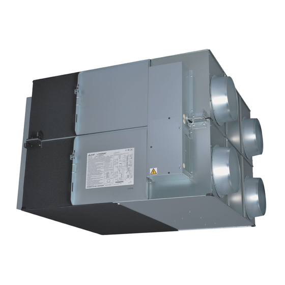
Lossnay Energy Recovery Ventilator
Models:
LGH-F300RX
-E, LGH-F470RX
5
Installation Instructions
Models LGH-F300, F470, F600RX
This product needs to be installed properly in order to ensure maximum functionality as well as safety.
Please make sure to read this installation manual before starting the installation.
Installation must be performed by a dealer or installation contractor. Please note that improper installation may cause malfunction or accident.
Separate booklet "Operating Instructions" is provided for the customer. The booklet and this manual must be handed over to the customer after completing the installation.
Safety precautions
The following signs indicate that death or serious injury may be caused by failure to heed the precautions described below.
Do not modify or disassemble.
(It could cause fire, electric shock or injury.)
Do not
disassemble
The Lossnay unit and remote controller should not be installed
where it is highly humid, like a bathroom, or other wet place.
(It could cause electric shock or power leakage.)
Prohibition of use in
bath or shower room
Connect the product properly to ground.
(Malfunctioning or power leaks can cause electrical shock.)
Connect the
grounding wire.
Do not place a burning appliance in a place where it is exposed
directly to the air from the Lossnay unit.
(It could cause an accident as a result of incomplete combustion.)
Do not use at a place where it is exposed to high temperatures
(104˚F (40˚C) or higher), naked flames, or in environment with
combustible fumes.
(It could cause fire.)
Do not use in an environment such as a chemical factory,
where hazardous gases such as acidic gases, alkaline gases,
Prohibited
organic solvent fumes, paint fumes, or gases containing
corrosive components are generated.
(It could cause malfunction.)
Do not install this product in a place where it is exposed to
ultraviolet light.
(UV may damage covering insulation.)
When using the product where it is exposed to high temperatures and humidity (104˚F
(40˚C) or higher, RH 80% or higher), or where fog occurs frequently, moisture is likely to
condense in the core, and may result in condensation build up in the unit. The product
should not be used under such conditions.
Outdoor air may enter the Lossnay owing to the pressure difference between
indoor and outdoor or external winds even when the product is not operated. It is
recommended to install an Electrically operated damper to block the outdoor air.
In a cold weather area, an area with strong external winds or where fog occurs frequently,
cold outdoor air, external winds or fog may be introduced into the product when its
operation is stopped. It is recommended to install an electrically operated damper.
5
-E
Model LGH-F1200RX
5
WARNING
CAUTION
CAUTION
-E, LGH-F1200RX
5
(For use by dealer/contractor)
Contents
-E
5
Safety precautions ..................................................................1
Outline drawings .....................................................................2
Standard installation examples ..........................................3
Installation method ................................................................3
Function settings .................................................................. 10
Trial operation ....................................................................... 12
Check points after installation work .............................. 14
Use the specified power supply and voltage.
(Use of incorrect power supply or voltage could cause fire or electric shock.)
Select a place with sufficient strength and install the main unit securely.
(It could cause injury if it falls.)
Wiring work must be performed by qualified professionals, and be
implemented safely and securely in accordance with the engineering
standards and the extension wiring rules for electrical equipment.
(Poor connection or improper wiring work could cause electric shock or fire.)
Install a power supply isolator at the power supply side as per local
electrical regulations. All supply circuits must be disconnected before
The instructions
obtaining access to the terminal devices. Use the specified cable size and
given must be
connect the cables securely to prevent disconnection when they are pulled.
followed.
(If there is a defect in the connection, there is a possibility of fire.)
Select an adequate place for the opening to introduce outdoor
air, where it will not intake the exhaust fumes like combustion
gas, or others, and there is no risk of blockage.
(Shortage of fresh air could put the room in a state of oxygen deficiency.)
A duct made of steel must be installed with care not to be connected
electrically with metals such as metal , wire , stainless steel plate, or others.
(It could cause fire when power leakage occurs.)
Put on gloves during installation. (It could cause injury.)
Make sure the power supply isolator is turned off on the power
distribution panel when Lossnay is not used for a long period
of time after the installation. (It could cause electric shock, power
leakage, or fire as a result of deteriorated insulation.)
Always use the specified suspension bolts, nuts and washers
and correctly rated wire / chain hangers. (Use of hardware with
insufficient strength could result in the product dropping.)
The outside ducts must be tilted at a gradient (1/30 or more)
down toward the outdoor louvres from Lossnay, and properly
insulated. (The entry of rain water may cause power leakage, fire,
The instructions
given must be
or damage to household property.)
followed.
The control box cover must be closed after the installation.
(Dust or humidity may cause power leakage or fire.)
When connecting external devices (electrically operated damper,
lamp, monitoring unit, etc.) using output signals of the Lossnay unit,
make sure to install safety equipment for the external devices.
(It could cause fire, damage, etc. without safety equipment.)
When using the product in an environment where there is a window, or opening near
the outdoor louvre , where insects are likely to gather around the interior or exterior
light , take note that small insects may intrude into the product.
In a cold weather area, or others, dewing or freezing could occur on the main unit,
where the duct is connected, or other sections, depending on the conditions of
outdoor air and indoor temperature and moisture, even if they are within the range
of operating conditions. Make sure to confirm the operating conditions and other
precautions, and do not use the product if dewing or freezing is anticipated.
*Example of dewing condition - Outdoor air: 23˚F (-5˚C) or lower, dew-point temperature at installation place: 50˚F (10˚C)
or higher (When the indoor temperature is 71.6˚F (22˚C) or higher with the relative humidity higher than 50%, or other)
1109875HC4901
-E
5
1
Publicité
Chapitres
Table des Matières

Manuels Connexes pour Mitsubishi Electric LGH-F300RX5-E


Sommaire des Matières pour Mitsubishi Electric LGH-F300RX5-E
-
Page 1: Table Des Matières
1109875HC4901 Lossnay Energy Recovery Ventilator Models: LGH-F300RX -E, LGH-F470RX -E, LGH-F600RX -E, LGH-F1200RX Installation Instructions (For use by dealer/contractor) Contents Models LGH-F300, F470, F600RX Model LGH-F1200RX Safety precautions ..............1 Outline drawings ..............2 Standard installation examples ..........3 Installation method ..............3 Function settings ..............10 Trial operation ............... -
Page 2: Outline Drawings
Outline drawings LGH-F300, F470, F600 RX *LGH-F470 and F600RX5 types Accessory parts Position where duct direction change is possible (4-9/16” X 13/16” (4-15 X 20) oval) Bypass damper plate • Mounting screws ............x16 Air exhaust fan Ceiling suspension fixture •... -
Page 3: Standard Installation Examples
Standard installation examples * Except F1200 RX • Duct length Return air grille Model Distance (not Included) LGH-F300 RX 3.3 ft (1 m) or more LGH-F470, F600 RX 8.2 ft (2.5 m) or more EA (exhaust air outlet) LGH- F1200 RX 9.8 ft (3 m) or more Lossnay unit •... -
Page 4: Connecting The Ducts
Installation method (continued) If the suspension bolts are short, change the CAUTION mounting hardware. • Before attaching the ducts, check that no (debris or any other) foreign matter (scraps of paper, vinyl, etc.) has found its way inside For the models LGH-F470 and F600 RX the ducts. -
Page 5: Electrical Installation
Installation method (continued) Electrical installation With this product, the wiring installation method will vary according to the design of the system. Perform electrical installation to meet local electrical regulations. * Always use double insulated PVC cable for the transmission cables. * Wiring work must be performed by qualified professionals. - Page 6 Installation method (continued) Wire connection diagram ----- Model LGH-F1200 RX * Connect the wires shown as thick lines. * Be sure to connect the ground wire. * A power supply isolator must be installed when wiring power supply to unit. * Always use a single pole isolator for the main switch power connection.
-
Page 7: Connecting The Power Supply Cable
When using the remote/local switching and the ON/OFF input (level signal) Control box cover When connecting to the City Multi, Lossnay remote controller (PZ-52SF-E) or Mitsubishi Electric Air-Conditioner Network System (MELANS). CAUTION • When connecting external devices (electrically operated damper, Screw lamp, monitoring unit, etc.) using output signals of the Lossnay unit,... - Page 8 Installation method (continued) Lossnay External controller input (TM2) (2) Confirm that the pulse input switch (SW2-2) is set to “OFF”. (Set to “OFF” at time of shipment.) AWG 20 (0.5 mm ) to AWG 17 (1 mm sheathed PVC cable External device Remote controller Lossnay...
- Page 9 When connecting to the City Multi, Lossnay remote controller (PZ-52SF- (When CO decreases: Closed) (Optional) PAC-SA88HA-E control board E) or Mitsubishi Electric Air-Conditioner Network System (MELANS) Brown 1 Red 2 CN16 * If centralized control is performed according the wire connection...
-
Page 10: Function Settings
When interlocking with Mitsubishi Free Plan air conditioner Address setting is required. (Refer to function setting section.) • Incase of PZ-60DR-E M-NET transmission cable: Connect any of the City Multi indoor unit, or Mitsubishi Electric Air-Conditioner Network Lossnay conditioner conditioner System (MELANS) - to the Lossnay. - Page 11 Function settings (continued) Settings for pulse input Bypass automatic ventilation priority setting Set as shown when connecting the pulse signal equipment from a Two thermistors in the Lossnay unit detect the indoor (RA) and outdoor building maintenance system to an external input. (OA) air temperatures and automatically select the “Lossnay ventilation”...
-
Page 12: Trial Operation
Function settings (continued) Exhaust fan stop during defrosting, exhaust fan Low speed Setting for TM3 67 output operation at outdoor air lower than 5˚F (-15˚C) Sets the operation of the exhaust fan (when the air supply fan is stopped) Operation during defrosting of the air conditioner when Mr. - Page 13 Trial operation (continued) 2. Stand-alone Lossnay trial operation 3. Complete system trial operation (1) Supply power to the Lossnay unit. Interlock system containing an indoor unit and/or external device (2) Turn the trial operation switch (SW2-1) “On. ” • Use the remote controller for the indoor unit or the operating switches •...
-
Page 14: Check Points After Installation Work
Check points after installation work After installation work, please double-check the points below. If there is any troubles, it must be done correctly. (1) Check points - Unit installation Is the insulation rapped around the outside ducts? [Refer to Installing the Lossnay unit] page 3 Is the outside ducts installed correctly? [Refer to Installation example]... -
Page 15: Ventilateur Lossnay À Récupération D'énergie Modèles
Ventilateur Lossnay à récupération d’énergie Modèles: LGH-F300RX -E. LGH-F470RX -E. LGH-F600RX -E. LGH-F1200RX Notice d’installation (destinée au revendeur/à l’entrepreneur) Sommaire Modèles LGH-F300. F470. F600RX Modèle LGH-F1200RX Consignes de sécurité ............15 Schémas d’encombrement ..........16 Exemples d’installations standard ......... 17 Méthode d’installation ............ -
Page 16: Schémas D'encombrement
Schémas d’encombrement LGH-F300. F470. F600 RX Mise en place possible au niveau du changement de sens du conduit *Les types LGH-F470. F600RX Pièces accessoires (4-9/16” X 13/16” (4-15 X 20) ovale) Plaque de l’obturateur de dérivation Ventilateur d’évacuation d’air • Vis de fixation .............x16 Ferrure de fixation au plafond (4-1/2”... -
Page 17: Exemples D'installations Standard
Exemples d’installations standard * Sauf le F1200 RX • Longueur du conduit Grille de reprise d’air Modèle Distance (Pas fourni) LGH-F300 RX 1 m ou plus LGH-F470. F600 RX 2,5 m ou plus LGH- F1200 RX 3 m ou plus (bouche d’évacuation d’air) Unité... -
Page 18: Méthode D'installation (Suite)
Méthode d’installation (suite) Si les boulons de suspension sont trop courts, ATTENTION changer la ferrure de suspension. • Avant de fixer les conduits, vérifiez l’absence de tous débris ou corps étrangers (bouts de papier, vinyle, etc..) à l’intérieur des Pour les modèles LGH-F470 et F600 RX conduits. -
Page 19: Travaux Électriques
Méthode d’installation (suite) Travaux électriques Sur cet élément, la méthode de câblage diffère selon la conception du système. L’installation électrique doit être conforme aux règlements locaux sur les installations électriques. * Utilisez toujours des câbles en PVC à double isolation comme câbles de transmission. * Les travaux de câblage doivent être accomplis par des professionnels qualifiés. - Page 20 Méthode d’installation (suite) Schéma de câblage ----- Modèle LGH-F1200 RX * Branchez les conducteurs illustrés par des lignes continues. * Veiller à toujours raccorder le fil de terre. * Installez un sectionneur de courant lorsque vous câblez l’unité sur le secteur. * Utilisez toujours un sectionneur de courant unipolaire pour la connexion sur le secteur.
-
Page 21: Raccordement Du Câble D'alimentation
à distance Lossnay (PZ-52SF-E) ou au système de réseau Couvercle du boîtier de commande de climatiseurs de Mitsubishi Electric (MELANS). ATTENTION • Lorsque vous branchez des dispositifs externes (humidificateur électrique, lampes, unité de monitorage, etc..) utilisant les signaux de sortie de l’unité... - Page 22 Méthode d’installation (suite) (2) Vérifier si le commutateur d’entrée d’impulsions (SW2-2) est réglé sur “OFF”. Entrée du contrôleur extérieur Lossnay (TM2) Câble avec gaine en PVC de 0,5 mm (Il est mis sur “OFF” à la sortie d’usine.) à 1 mm de section Dispositif externe Commutateur...
- Page 23 Lors du raccordement à un climatiseur City Multi, à un commutateur de commande à distance Capteur de CO , etc.. Tableau de Marche/Arrêt Lossnay (PZ-52SF-E) ou au système de réseau de climatiseurs de Mitsubishi Electric (MELANS). (Facultatif) PAC-SA88HA-E (Lorsque CO diminue : Fermé) commande Lossnay Marron 1 * Si vous centralisez la commande de la façon illustrée dans cette...
-
Page 24: Configuration Des Fonctions
Méthode d’installation (suite) • Un conducteur blindé est branché sur TB5 S de la carte à circuit En cas de synchronisation avec un climatiseur à plan libre Mitsubishi imprimé de la plaque à bornes. Vous devez configurer l’adresse. (Consultez la section de configuration des •... - Page 25 Configuration des fonctions (suite) Réglage de la priorité de la ventilation automatique de Configuration de l’entrée impulsion dérivation Configurez de la façon illustrée si vous branchez l’appareil de signal à Dans l’unité Lossnay deux thermistors détectent la température de l’air impulsion d’un système d’entretien d’immeuble sur une entrée extérieure.
-
Page 26: Configuration Des Fonctions (Suite)
Configuration des fonctions (suite) Arrêt du ventilateur de soufflage pendant le dégivrage, fonctionnement du ventilateur Configuration de la sortie TM3 67 de soufflage à la vitesse basse si la température de l’air extérieur est inférieure à -15°C Configure le fonctionnement du ventilateur de soufflage (lorsque le Fonctionnement ventilateur d’aspiration est arrêté) pendant le dégivrage du climatiseur si Sortie du moniteur de fonctionnement de la ventilation de dérivation... -
Page 27: Essai De Fonctionnement (Suite)
Essai de fonctionnement (suite) 2. Essai de fonctionnement indépendant de l’unité Lossnay 3. Essai de fonctionnement complet du système (1) Retirer le couvercle du boîtier de commande. Système couplé comprenant une unité intérieure et/ou un dispositif extérieur. (2) Tourner le commutateur d’essai de fonctionnement (SW2-1) et le mettre sur “On. ” •... -
Page 28: Points De Contrôle Après L'installation
Points de contrôle après l'installation Une fois l'installation terminée, vérifiez soigneusement les points suivants. Tout problème détecté doit être correctement résolu. (1) Points de contrôle - Installation de l'unité Les conduits extérieurs sont-ils correctement isolés ? [Consultez le Installation de l’unité Lossnay] page 17 Les conduits extérieurs sont-ils correctement installés ? [Consultez le Exemples d’installations]...