Alcad GRF-304 Mode D'emploi
Table des Matières
Liens rapides
DOOR-VIDEODOOR ENTRY SYSTEMS WITH PUSH-BUTTONS
INDEX
ELEMENTS AND DIMENSIONS....................................................................................................................................2
DESCRIPTION .............................................................................................................................................................3
OPERATION ...............................................................................................................................................................4
OVERVIEW OF THE INSTALLATION: WIRING...............................................................................................................6
HOW TO CONNECT THE AUDIO UNIT TO THE PUSHBUTTON PANEL ........................................................................13
EXTENDING INSTALLATIONS ....................................................................................................................................14
INSTALLING AND ADJUSTMENT INSTRUCTIONS .......................................................................................................15
TECHNICAL CHARACTERISTICS .................................................................................................................................23
TROUBLE SHOOTING ...............................................................................................................................................25
2 - W I R E
2-WIRE VIDEODOOR ENTRY SYSTEM
D O O R
E N T R Y
S Y S T E M S
2-WIRE DOOR ENTRY SYSTEM
Table des Matières

Manuels Connexes pour Alcad GRF-304


Sommaire des Matières pour Alcad GRF-304
-
Page 1: Table Des Matières
2 - W I R E D O O R E N T R Y S Y S T E M S DOOR-VIDEODOOR ENTRY SYSTEMS WITH PUSH-BUTTONS 2-WIRE VIDEODOOR ENTRY SYSTEM 2-WIRE DOOR ENTRY SYSTEM INDEX ENTRANCE PANELS: UPPER MODULE WITH AUDIO UNIT ELEMENTS AND DIMENSIONS............................2 2-WIRE SYSTEM WITH PUSHBUTTONS DESCRIPTION ................................3... -
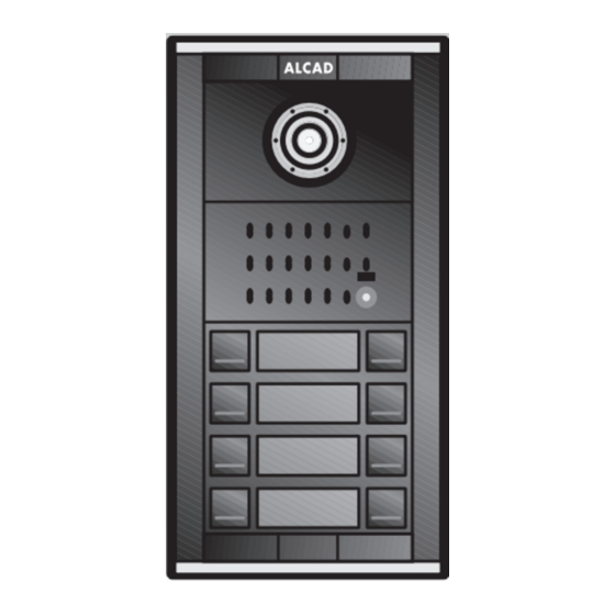
Page 2: Entrance Panels: Upper Module With Audio Unit
MODULE B: See the datasheet of the pushbutton entrance panel. Audio unit module for external entrance, 2-wire system. Includes a GRF-304 audio unit, a front module of entrance panel and a RVE- 014 speaker and microphone module. Audio unit for external entrance, 2-wire system (does not include speaker and microphone module). -
Page 3: 2-Wire System With Pushbuttons
2 - W I R E D O O R E N T R Y S Y S T E M S 2-WIRE SYSTEM WITH PUSHBUTTONS DESCRIPTION System which makes it possible to perform installations in buildings with one or several points of entry and in compounds containing several inner buildings. -
Page 4: Operation
2 - W I R E D O O R E N T R Y S Y S T E M S OPERATION There are two operating states: system on standby and system active. SYSTEM ON STANDBY By default the telephones/monitors are inactive, so that the functions of communicating with the entrance panel and opening the door are disabled. - Page 5 2 - W I R E D O O R E N T R Y S Y S T E M S THE LOOPED AUTO-SWITCH-ON FUNCTION. 2-WIRE VIDEO DOOR ENTRY SYSTEM The auto-switch-on function makes it possible to see the image on the monitor, communicate with the entrance panel and open the door without having received a call.
-
Page 6: Overview Of The Installation: Wiring
2 - W I R E D O O R E N T R Y S Y S T E M S OVERVIEW OF THE INSTALLATION: WIRING DOOR ENTRY SYSTEM. COMPOUND OF 1 TO 4 BUILDINGS For distances, number of buildings, devices, or types of cable different from those shown in the tables, additional elements may be necessary (e.g. - Page 7 2 - W I R E D O O R E N T R Y S Y S T E M S DOOR ENTRY SYSTEM. COMPOUND OF 1 TO 4 BUILDINGS For distances, number of devices, or types of cable different from those shown in the tables, additional elements may be necessary (e.g.
- Page 8 2 - W I R E D O O R E N T R Y S Y S T E M S DEVICES COMPATIBLE WITH EACH OTHER Some devices with 2-wire system are incompatible with others. Do not mix devices from group A with devices from group B in the same installation.
-
Page 9: Compound, 3 Buildings Of 8 Dwellings Each. 1 External Point Of Entry (Gatehouse)
2 - W I R E D O O R E N T R Y S Y S T E M S COMPOUND, 3 BUILDINGS OF 8 DWELLINGS EACH. 1 EXTERNAL POINT OF ENTRY (GATEHOUSE) SINGLE-WIRED DIAGRAM B2 B1 B2 B1 B2 B1 DIV-054 DIV-054... - Page 10 2 - W I R E D O O R E N T R Y S Y S T E M S REMARKS Identifying the entrance panels of the buildings Assign an identification number to each building, see "Entrance panel configuration instructions", page 18 Configuring the entrance panels Configure the entrance panel of the external access point as an external panel, see "Entrance panel configuration instructions", page Identify the pushbuttons of the external panel with the buildings inside, see "Outer entrance panel: assigning pushbuttons to each...
- Page 11 COMPOUND, 3 BUILDINGS OF 8 DWELLINGS EACH. 1 EXTERNAL POINT OF ENTRY (GATEHOUSE) WIRING DIAGRAM OF THE EXTERNAL POINT OF ENTRY BUILDING 1 BUILDING 1 BUILDING 3 DIV-154 cod. 9730071 B1B2 B1B2 B1B2 B1B2 B1B2 External entrance panel GRF-304 cod. 9610048 Protective element...
- Page 12 2 - W I R E D O O R E N T R Y S Y S T E M S COMPOUND, 3 BUILDINGS OF 8 DWELLINGS EACH. 1 EXTERNAL POINT OF ENTRY (GATEHOUSE) WIRING DIAGRAM OF BUILDINGS B2 B1 Building 2.
-
Page 13: How To Connect The Audio Unit To The Pushbutton Panel
E N T R Y S Y S T E M S HOW TO CONNECT THE AUDIO UNIT TO THE PUSHBUTTON PANEL HOW TO CONNECT RPD-011, RPS-011, RPD-012, RPS-012 Entrance panel Audio unit GRF-304 cod. 9610048 12 12c 18 SC1 B4 B5 SC0 22... -
Page 14: Extending Installations
5 A max. Electric lock: Protective element: Place it on the terminals of the audio unit where you intend to connect the electric lock. GRF-304 cod. 9610048 12 12c 18 SC1 B4 B5 Activation of accessories (models ASC-001, ASC-051, etc.) using auxiliary pushbuttons of the telephone/monitor Aux. -
Page 15: Installing And Adjustment Instructions
2 - W I R E D O O R E N T R Y S Y S T E M S INSTALLING AND ADJUSTMENT INSTRUCTIONS - RECOMMENDATIONS - Before fixing the entrance panel to the pins of the flush-mounted box, put the audio unit in position and make the connections. It is much easier to make the connections in this way. - Page 16 2 - W I R E D O O R E N T R Y S Y S T E M S Place the front module in the window of the pushbutton panel in such a way that the tabs of this module (1) clip into the guides on the sides of the window (2).
- Page 17 2 - W I R E D O O R E N T R Y S Y S T E M S Programme each telephone/connections bracket from the main entrance panel of the building. (see the technical datasheet that comes with the Code depending on the pushbutton connections bracket/telephone).
-
Page 18: Entrance Panel Configuration Instructions
2 - W I R E D O O R E N T R Y S Y S T E M S ENTRANCE PANEL CONFIGURATION INSTRUCTIONS Assign a different identification number to each building, beginning with number 1. For example: for 3 buildings, assign the numbers 1, 2 and 3;... - Page 19 2 - W I R E D O O R E N T R Y S Y S T E M S OUTER ENTRANCE PANEL: ASSIGNING PUSHBUTTONS TO EACH BUILDING DESCRIPTION In compounds with several inner buildings, before being able to make a call from the external point of entry to the different dwellings, it is necessary to tell the system which pushbuttons correspond to each of the inner buildings.
- Page 20 2 - W I R E D O O R E N T R Y S Y S T E M S EXAMPLE OF ASSIGNING PUSHBUTTONS TO BUILDINGS: Compound of 24 dwellings, distributed in 3 buildings of 8 dwellings each EXTERNAL ENTRANCE PANEL CONSISTING OF 1 PANEL OF 24 PUSHBUTTONS Assigning Pushbuttons Flats...
- Page 21 STEPS FOR ASSIGNING PUSHBUTTONS TO BUILDINGS Set microswitch 3 of the SW1 switch of the GRF-304 audio unit to the ON position (i.e. the upper position). Press the right pushbutton on the bottom row of pushbuttons a single time. By doing so, this pushbutton is assigned to dwelling number 1 (i.e.
- Page 22 2 - W I R E D O O R E N T R Y S Y S T E M S STEPS FOR ASSIGNING PUSHBUTTONS TO BUILDINGS Press each pushbutton once only. Dwelling 1. Building 1 Last dwelling. Building 1 Dwelling 1.
-
Page 23: Technical Characteristics
Note: Reference values are provided only to enable the checking of equipment and are reliable. Do not use the terminals of the equipment to feed additional devices without first consulting the manufacturer. - AUDIO UNIT GRF-304 - Voltage POWER SUPPLY... - Page 24 2 - W I R E D O O R E N T R Y S Y S T E M S...
-
Page 25: Trouble Shooting
2 - W I R E D O O R E N T R Y S Y S T E M S TROUBLE SHOOTING To program the connection brackets/telephones, make sure that you connection B1, B2 of the power supply unit interface to the are doing so in the main entrance panel of the building and that only monitors/telephones. - Page 26 2 - W I R E D O O R E N T R Y S Y S T E M S Automatic switch-on does not work on any monitor/telephone from 1 to 5 (see “Configuring a secondary entrance panel ). If no Check that the system is not engaged.
- Page 27 2 - W I R E D O O R E N T R Y S Y S T E M S...
- Page 28 2 - W I R E D O O R E N T R Y S Y S T E M S 17 Nov 2011...