Masquer les pouces Voir aussi pour ALS-020:

Publicité

Les langues disponibles

Les langues disponibles

Liens rapides

KITS
ALS-020 DIV-061 GRF-302 RVE-014 RVE-017 RPS-012 RPS-011 TET-002
KIT 1 VIVIENDA
1 DWELLING KIT
KIT 1 LOGEMENT
B1
B2
TET-002
Tabla de secciones
Section table
Tableau de sections
A: 870m
CAB-207
B: 145m
2
(1mm
)
C: 870m
A: 405m
CAB-007
B: 145m
2
(1mm
)
C: 405m
A: 405m
CAB-004
B: 70m
2
(0,5mm
)
C: 405m
A: 405m
CAB-032
B: 35m
2
(0.25mm
)
C: 405m
A: 675m
TCA-100
B: 30m
(UTP CAT6)
C: 675m
PULSADOR DE SALIDA
EXIT BUTTON
OUVRE-PORTE LOCAL
11 12 12
GRF-302
+
ABR-015
PORTERO 2 HILOS
C
230V
B1 B2 B2 B3
~
~
ALS-020
B
+ –
S
S
+
18
C
C
22
B3 B2 B4 B5
c
1
0
-
2-WIRE DOOR ENTRY SYSTEMS
Tabla de secciones
Section table
Tableau de sections
A: 430m
CAB-207
B: 145m
2
(1mm
)
C: 430m
A: 200m
CAB-007
B: 145m
2
(1mm
)
C: 200m
A: 200m
CAB-004
B: 70m
2
(0,5mm
)
C: 200m
A
A: 200m
CAB-032
B: 35m
2
(0.25mm
)
C: 200m
A: 330m
TCA-100
B: 30m
(UTP CAT6)
C: 330m
MANUAL DE INSTALACIÓN
INSTALLATION DATA SHEET
FEUILLE D'INSTALLATION
KIT 2 VIVIENDAS
2 DWELLINGS KIT
KIT 2 LOGEMENTS
B1 B2
RVE-017
DIV-061
B1
B2
TET-002
ALS-020
PULSADOR DE SALIDA
EXIT BUTTON
OUVRE-PORTE LOCAL
S
S
11 12 12
18
C
C
c
1
0
GRF-302
+
ABR-015
-
PORTIER 2 FILS
B1
B2
TET-002
C
DIV-061
A
230V
B1 B2 B2 B3
~
~
B
+ –
+
22
B3 B2 B4 B5
...................2
..................12
..................22

Publicité

Table des Matières
loading

Sommaire des Matières pour Alcad ALS-020

  • Page 1 PORTERO 2 HILOS 2-WIRE DOOR ENTRY SYSTEMS PORTIER 2 FILS KITS ALS-020 DIV-061 GRF-302 RVE-014 RVE-017 RPS-012 RPS-011 TET-002 KIT 1 VIVIENDA KIT 2 VIVIENDAS 1 DWELLING KIT 2 DWELLINGS KIT KIT 1 LOGEMENT KIT 2 LOGEMENTS B1 B2 RVE-017...
  • Page 2: Table Des Matières

    PORTERO 2 HILOS ÍNDICE ELEMENTOS Y DIMENSIONES ........................2 INSTALACIÓN DE ELEMENTOS ADICIONALES ..................3 CONEXIÓN ABREPUERTAS AC ......................3 CONEXIÓN ABREPUERTAS INVERSO ....................3 TELÉFONOS ADICIONALES ........................4 PULSADOR AUXILIAR DEL TELÉFONO ....................5 INSTRUCCIONES DE INSTALACIÓN ......................6 ALIMENTADOR ............................
  • Page 3: Instalación De Elementos Adicionales

    PORTERO 2 HILOS PLACA DE CALLE - MÓDULOS INTERIORES 9770035 RVE-014 9610044 Micrófono Altavoz GRF-302 9770049 RPS-012 Grupo fónico 9770048 RPS-011 Grupo de pulsadores INSTALACIÓN DE ELEMENTOS ADICIONALES CONEXIÓN ABREPUERTAS AC + – – 11 12 12 GRF-302 230V ABR-001 ALA-040 Máx.
  • Page 4: Teléfonos Adicionales

    Una vez conectados, prográmelos tal y como se explica en las hojas de instalación incluidas en dichos equipos. DIV-061 TET-002 DIV-061 TET-002 230V B1 B2 B2 B3 ALS-020 ESP-4...
  • Page 5: Pulsador Auxiliar Del Teléfono

    PORTERO 2 HILOS PULSADOR AUXILIAR DEL TELÉFONO Conexión desde la placa de calle (mediante accesorio APX-012 no incluido en el Kit) + – – 11 12 12 B3 B2 B4 B5 GRF-302 + – APX-012 CONTACTO SECO (AUX1) Máx. 1A - 24V –...
  • Page 6: Instrucciones De Instalación

    PORTERO 2 HILOS INSTRUCCIONES DE INSTALACIÓN INTERFACE ALIMENTADOR Consulte las instrucciones de seguridad al fi nal del presente documento. Proteja el alimentador, cumpliendo con la normativa vigente en materia de instalaciones eléctricas (magneto térmicos, diferenciales...). Montaje a pared Montaje en carril DIN TELÉFONO A la hora de elegir el lugar para colocar el teléfono, busque una zona de pared plana, uniforme y dura.
  • Page 7: Caja De Empotrar

    PORTERO 2 HILOS TELÉFONO CAJA DE EMPOTRAR Rompa el tabique de las aberturas que requiera para pasar los cables, y coloque la caja de empotrar de modo que la parte superior quede a una altura de 1,7 m. 1,7 m ESP-7...
  • Page 8: Placa De Calle

    MR. SMITH TARJETAS IDENTIFICADORAS DE LOS PULSADORES: Puede utilizar las tarjetas preimpresas que se suministran o utilizar la plantilla que encontrará en la página Web de Alcad: www.alcad.net, dentro del apartado Soporte técnico. CLICK! ESP-8...
  • Page 9: Características Técnicas

    Activo: 90 mA TEMPERATURA DE FUNCIONAMIENTO: +5.. +55 TENSIONES USUALES SEGÚN EL ESTADO DEL EQUIPO BORNAS REPOSO TRABAJO B2, B1 10 - 18 V INTERFACE ALIMENTADOR ALS-020 ALS-020 Tensión: 230 V~ ±15% 50/60Hz ALIMENTACIÓN DE RED: Corriente: 350 mA (máx.) Tensión:...
  • Page 10: Solución De Problemas

    PORTERO 2 HILOS GRUPO FÓNICO GRF-302 GRF-302 Tensión: 12,5 - 18 V ALIMENTACIÓN: Corriente: 350 mA (máx.) TEMPERATURA DE FUNCIONAMIENTO: -10.. +55 TENSIONES USUALES SEGÚN EL ESTADO DEL EQUIPO BORNAS REPOSO TRABAJO +,– 12,5 - 18 V B3, B2 12,5 - 18 V B5, B4 12,5 - 18 V 22, 18...
  • Page 11: No Se Oye La Placa De Calle En Ningún Teléfono

    PORTERO 2 HILOS No se oye la placa de calle en ningún No se oye ningún teléfono desde la pla- teléfono ca de calle Compruebe la conexión 30 entre el módulo altavoz- Compruebe la conexión 30 entre el módulo altavoz- micrófono y el grupo fónico.
  • Page 12: Elements And Dimensions

    2-WIRE DOOR ENTRY SYSTEMS INDEX ELEMENTS AND DIMENSIONS ......................... 12 INSTALLATION OF ADDITIONAL ELEMENTS ................... 13 HOW TO CONNECT AC ELECTRIC LOCK ................... 13 HOW TO CONNECT INVERSE ELECTRIC LOCK ................... 13 ADDITIONAL TELEPHONES ......................... 14 TELEPHONE AUXILIARY PUSH-BUTTON ....................15 INSTALLING INSTRUCTIONS ........................
  • Page 13: Installation Of Additional Elements

    2-WIRE DOOR ENTRY SYSTEMS ENTRANCE PANEL - INSIDE MODULES 9770035 RVE-014 9610044 Microphone GRF-302 Speaker 9770049 RPS-012 Audio unit 9770048 RPS-011 Push-button set INSTALLATION OF ADDITIONAL ELEMENTS HOW TO CONNECT AC ELECTRIC LOCK + – – 11 12 12 GRF-302 230V ABR-001 ALA-040...
  • Page 14: Additional Telephones

    It is possible to install up to 6 telephones which respond to the same call from the entrance panel. When the devices are connected, program them following the installation instructions which accompany the devices. DIV-061 TET-002 DIV-061 TET-002 230V B1 B2 B2 B3 ALS-020 ENG-14...
  • Page 15: Telephone Auxiliary Push-Button

    2-WIRE DOOR ENTRY SYSTEMS TELEPHONE AUXILIARY PUSH-BUTTON Connection from the entrance panel (using accessory APX-012, not included in the kit) + – – 11 12 12 B3 B2 B4 B5 GRF-302 + – APX-012 DRY CONTACT (AUX1) Max. 1A - 24V –...
  • Page 16: Installing Instructions

    2-WIRE DOOR ENTRY SYSTEMS INSTALLING INSTRUCTIONS POWER SUPPLY UNIT See the safety instructions at the end of this booklet. Protect the power supply unit by complying with existing regulations governing electrical installations (avoid high-temperature locations and strong magnetic fi elds, ensure correct fusing, etc.).
  • Page 17: Flush Mounted Box

    2-WIRE DOOR ENTRY SYSTEMS TELEPHONE FLUSH MOUNTED BOX Break off the perforated holes that you need to pass the cables through, and place the fl ush-mounted box in position so that the top is 1.7 m high. 1,7 m ENG-17...
  • Page 18: Entrance Panel

    Fit the audio unit inside the fl ush-mounted box. Then slide the pushbutton identifi cation cards of the entrance panel into place. MR. SMITH PUSHBUTTON IDENTIFICATION CARDS: You can use either the preprinted cards which are provided or print your own using the template available from the Technical Support section of the Alcad web site: www.alcad.net. CLICK! ENG-18...
  • Page 19: Technical Characteristics

    OPERATING TEMPERATURE: +5.. +55 NORMAL VOLTAGES DEPENDING ON THE STATE OF THE EQUIPMENT TERMINALS AT REST WORKING B2, B1 10 - 18 V POWER SUPPLY UNIT ALS-020 ALS-020 Voltage: 230 V~ ±15% 50/60Hz MAINS SUPPLY: Current: 350 mA (max.) Voltage:...
  • Page 20: Trouble Shooting

    2-WIRE DOOR ENTRY SYSTEMS AUDIO UNIT GRF-302 GRF-302 Voltage: 12,5 - 18 V POWER SUPPLY: Current: 350 mA (max.) OPERATING TEMPERATURE: -10.. +55 NORMAL VOLTAGES DEPENDING ON THE STATE OF THE EQUIPMENT TERMINALS AT REST WORKING +,– 12,5 - 18 V B3, B2 12,5 - 18 V B5, B4...
  • Page 21 2-WIRE DOOR ENTRY SYSTEMS lowest position (put the cancelled speaker symbol). If The entrance panel cannot be heard on no fault is detected, the telephone or the pushbutton any telephone of the panel may be defective. Check connection 30 between the speaker- microphone module and the audio unit.
  • Page 22: Éléments Et Mesures

    PORTIER 2 FILS SOMMAIRE ÉLÉMENTS ET MESURES ..........................22 INSTALLATION D’ÉLÉMENTS ADDITIONNELS ..................23 BRANCHEMENT GÂCHES AC À RUPTURE ..................23 BRANCHEMENT GÂCHE À ÉMISSION ....................23 TÉLÉPHONES ADDITIONNELS ......................24 BOUTON AUXILIAIRE DU TÉLÉPHONE....................25 INSTRUCTIONS D’INSTALLATION ......................26 ALIMENTATION ..........................
  • Page 23: Installation D'éléments Additionnels

    PORTIER 2 FILS PLAQUE DE RUE - MODULES INTÉRIEURS 9770035 RVE-014 9610044 Micro Haut-parler GRF-302 9770049 RPS-012 Groupe phonique 9770048 RPS-011 Groupe avec bouton-poussoir INSTALLATION D’ÉLÉMENTS ADDITIONNELS BRANCHEMENT GÂCHES AC À ÉMISSION + – – 11 12 12 GRF-302 230V ABR-001 ALA-040 Max.
  • Page 24: Téléphones Additionnels

    PORTIER 2 FILS TÉLÉPHONES ADDITIONNELS B1 B2 RVE-017 DIV-061 TET-002 EXTENSION AVEC TÉLÉPHONES : Il est possible d’installer jusqu’à 6 téléphones qui répondent au même appel de la plaque d’entrée. Quand les dispositifs sont connectés, programmez- les en suivant les instructions d’installation qui accompagnent les dispositifs.
  • Page 25: Bouton Auxiliaire Du Téléphone

    PORTIER 2 FILS BOUTON AUXILIAIRE DU TÉLÉPHONE Connexion depuis la plaque d’entrée (à l’aide de l’accessoire APX-012, non inclus dans le kit) + – – 11 12 12 B3 B2 B4 B5 GRF-302 + – APX-012 CONTACT SEC (AUX1) Max. 1A - 24V –...
  • Page 26: Instructions D'installation

    PORTIER 2 FILS INSTRUCTIONS D’INSTALLATION ALIMENTATION Veuillez vous en référer aux instructions de sécurité à la fi n de ce document. Protéger l’alimentation, en accord avec la norme en matière d’installation électrique (magnéto thermiques, différentiels...) Montage sur le mur Montage sur rail DIN TÉLÉPHONE Pour positionner le support de connexions, choisissez une surface de mur plane, uniforme et dure.
  • Page 27: Boîtier Encastrable

    PORTIER 2 FILS TÉLÉPHONE BOÎTIER ENCASTRABLE Cassez la cloison des ouvertures nécessaires pour faire passer les câbles, et Placez le boîtier encastrable de telle sorte que la partie supérieure soit placée à une hauteur de 1,7 m. 1,7 m FRA-27...
  • Page 28: Plaque De Rue

    MR. SMITH CARTES D’IDENTIFICATION DES BOUTONS-POUSSOIR : Vous pouvez utiliser les étiquettes pré-imprimées qui sont fournies ou imprimer les vôtres à partir du modèle qui se trouve dans la section Support Technique de la page Web d’Alcad: www.alcad.net. CLICK! FRA-28...
  • Page 29: Caractéristiques Techniques

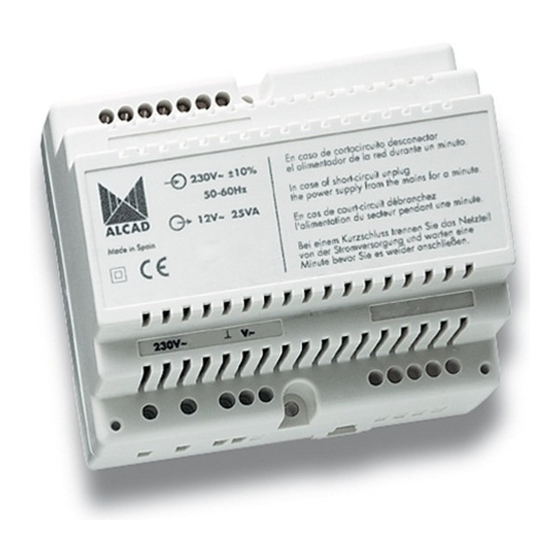
    Travail: 90 mA TEMPÉRATURE DE TRAVAIL: +5.. +55 TENSIONS USUELLES EN FONCTION DE L’ÉTAT DE L’ÉQUIPEMENT BORNES VEILLE TRAVAIL B2, B1 10 - 18 V ALIMENTATION ALS-020 ALS-020 Tension: 230 V~ ±15% 50/60Hz ALIMENTATION DE RÉSEAU: Courant: 350 mA (max.) Tension:...
  • Page 30: Problèmes De Fonctionnement

    PORTIER 2 FILS GROUPE PHONIQUE GRF-302 GRF-302 Tension: 12,5 - 18 V ALIMENTATION: Courant: 350 mA (max.) TEMPÉRATURE DE TRAVAIL: -10.. +55 TENSIONS USUELLES EN FONCTION DE L’ÉTAT DE L’ÉQUIPEMENT BORNES VEILLE TRAVAIL +,– 12,5 - 18 V B3, B2 12,5 - 18 V B5, B4 12,5 - 18 V...
  • Page 31: On N'entend Aucun Téléphone À La Plaque De Rue

    Especificaciones sujetas a modificación sin previo aviso Specifications subject to modifications without prior notice Les spécifications sont soumises à de possible modifications sans avis préalable ALCAD Electronics, S.L. Pol. Ind. Arreche-Ugalde, 1 Apdo. 455 | 20305 IRUN - Spain Tel. (+34) 943 63 96 60 www.alcadelectronics.com...

Ce manuel est également adapté pour:

Div-061Grf-302Rve-014Rve-017Rps-012Rps-011 ... Afficher tout

Table des Matières