Télécharger Imprimer la page
Masquer les pouces Voir aussi pour ALS-020:

Publicité

Les langues disponibles

Les langues disponibles

Liens rapides

VIDEO PORTERO 2 HILOS
KITS
ALS-020 GRF-302 MVC-130 SCM-150 TCB-072 RVE-014 RPS-011
*
REPETIDOR DE LLAMADA
CALL EXTENSION
SONNERIE DEPORTÉE
AAL-200
TABLA DE SECCIONES
SECTION TABLE
TABLEAU DE SECTIONS
CAB-207
CAT-001
2
1 mm
UTP
AWG:17
CAT 5E
A
250 m
40 m
125 m
20 m
B
C
125 m
20 m
-
2-WIRE VIDEO DOOR ENTRY SYSTEMS
*
CAB-007
CAB-004
CAB-032
2
2
2
1 mm
0.5 mm
0.25 mm
AWG:17
AWG:20
AWG:22
200 m
120 m
60 m
125 m
60 m
30 m
125 m
60 m
30 m
GRF-302
*
MVC-130
+
SCM-150
LLAMADA RELLANO
LANDING CALL
APPEL PALIER
* No incluido en el Kit
* Not included in the Kit
* Non inclus dans le Kit
11 12 12 c 18
+
15 V
500mA
MANUAL DE INSTALACIÓN
INSTALLATION DATA SHEET
FEUILLE D'INSTALLATION
-
VIDEO PORTIER 2 FILS
SW1
– +
B
230V
~
~
ALS-020
+ –
S
S
+
C
C
1
0
*
APERTURA DE PUERTA
EXIT BUTTON
OUVRE-PORTE LOCAL
A
16 – 20 V
C
A
B
12.5 – 20 V
...................2
..................12
..................22

Publicité

loading

Sommaire des Matières pour Alcad ALS-020

  • Page 1 VIDEO PORTERO 2 HILOS 2-WIRE VIDEO DOOR ENTRY SYSTEMS VIDEO PORTIER 2 FILS KITS ALS-020 GRF-302 MVC-130 SCM-150 TCB-072 RVE-014 RPS-011 – + REPETIDOR DE LLAMADA 16 – 20 V MVC-130 CALL EXTENSION SONNERIE DEPORTÉE SCM-150 AAL-200 LLAMADA RELLANO LANDING CALL...
  • Page 2: Table Des Matières

    VIDEO PORTERO 2 HILOS ÍNDICE ELEMENTOS Y DIMENSIONES ........................2 INSTALACIÓN DE ELEMENTOS ADICIONALES ..................3 CONEXIÓN ABREPUERTAS AC ......................3 CONEXIÓN ABREPUERTAS INVERSO ....................3 MONITORES O TELÉFONOS ADICIONALES..................4 PULSADORES AUXILIARES DEL MONITOR ..................... 4 INSTRUCCIONES DE INSTALACIÓN ......................6 ALIMENTADOR ............................
  • Page 3: Instalación De Elementos Adicionales

    VIDEO PORTERO 2 HILOS PLACA DE CALLE - MÓDULOS INTERIORES 9640017 Micrófono TCB-072 9610044 Telecámara GRF-302 color 9770035 RVE-014 Altavoz Grupo fónico 9770048 RPS-011 Grupo de pulsadores INSTALACIÓN DE ELEMENTOS ADICIONALES CONEXIÓN ABREPUERTAS AC + – – 11 12 12 GRF-302 230V ABR-001...
  • Page 4: Monitores O Teléfonos Adicionales

    TET-002 MVC-130 + SCM-150 230V ALS-020 * No incluido en el Kit PULSADORES AUXILIARES DEL MONITOR A. Conexión desde el monitor – + MVC-130 SCM-150...
  • Page 5 VIDEO PORTERO 2 HILOS PULSADORES AUXILIARES DEL MONITOR B. Conexión desde la placa de calle (mediante accesorio APX-012 no incluido en el Kit) – + MVC-130 SCM-150 230V ALS-020 + – – 11 12 12 GRF-302 + – APX-012 CONTACTO SECO...
  • Page 6: Instrucciones De Instalación

    VIDEO PORTERO 2 HILOS INSTRUCCIONES DE INSTALACIÓN INTERFACE ALIMENTADOR Consulte las instrucciones de seguridad al fi nal del presente documento. Proteja el alimentador, cumpliendo con la normativa vigente en materia de instalaciones eléctricas (magneto térmicos, diferenciales...). Montaje a pared Montaje en carril DIN SOPORTE DE CONEXIONES DE MONITOR Elija una zona de pared plana, uniforme y dura.
  • Page 7: Monitor

    VIDEO PORTERO 2 HILOS MONITOR Una vez realizadas las conexiones, conecte el latiguillo del monitor en el soporte de conexiones y fíjelo tal y como se muestra en la imagen. 20mm 20mm CAJA DE EMPOTRAR Rompa el tabique de las aberturas que requiera para pasar los cables, y coloque la caja de empotrar de modo que la parte superior quede a una altura de 1,7 m.
  • Page 8: Placa De Calle

    MR. SMITH TARJETAS IDENTIFICADORAS DE LOS PULSADORES: Puede utilizar las tarjetas preimpresas que se suministran o utilizar la plantilla que encontrará en la página Web de Alcad: www.alcad.net, dentro del apartado Soporte técnico. CLICK! ESP-8...
  • Page 9: Características Técnicas

    SENSOR: CCD Color 1/3” ILUMINACIÓN: Leds Blancos H: 60 ÁNGULO DE VISIÓN: V: 45 ORIENTACIÓN: TEMPERATURA DE FUNCIONAMIENTO: -10.. +55 INTERFACE ALIMENTADOR ALS-020 ALS-020 Tensión: 230 V~ ±15% 50/60Hz ALIMENTACIÓN DE RED: Corriente: 350 mA (máx.) Tensión: 18 V SALIDAS: Corriente: 2 A (máx.)
  • Page 10 VIDEO PORTERO 2 HILOS GRUPO FÓNICO GRF-302 GRF-302 Tensión: 12,5 - 18 V ALIMENTACIÓN: Corriente: 350 mA (máx.) TEMPERATURA DE FUNCIONAMIENTO: -10.. +55 TENSIONES USUALES SEGÚN EL ESTADO DEL EQUIPO BORNAS REPOSO TRABAJO +,– 12,5 - 18 V B3, B2 12,5 - 18 V B5, B4 12,5 - 18 V...
  • Page 11: Solución De Problemas

    VIDEO PORTERO 2 HILOS SOLUCIÓN DE PROBLEMAS No funciona nada La placa de calle no emite ningún sonido Compruebe si el led del interface-alimentador está al llamar apagado. Verifi que si suena la llamada en el monitor; en caso Con led apagado: a) verifi que la tensión de red, b) afi...
  • Page 12 2-WIRE VIDEO DOOR ENTRY SYSTEMS INDEX ELEMENTS AND DIMENSIONS ......................... 12 INSTALLATION OF ADDITIONAL ELEMENTS ................... 13 HOW TO CONNECT AC ELECTRIC LOCK ................... 13 HOW TO CONNECT INVERSE ELECTRIC LOCK ................... 13 ADDITIONAL MONITORS OR TELEPHONES ..................14 MONITOR AUXILIARY PUSH-BUTTONS ....................14 INSTALLING INSTRUCTIONS ........................
  • Page 13: Installation Of Additional Elements

    2-WIRE VIDEO DOOR ENTRY SYSTEMS ENTRANCE PANEL - INSIDE MODULES 9640017 Microphone TCB-072 9610044 Colour video GRF-302 unit 9770035 RVE-014 Speaker Audio unit 9770048 RPS-011 Push-button set INSTALLATION OF ADDITIONAL ELEMENTS HOW TO CONNECT AC ELECTRIC LOCK + – – 11 12 12 GRF-302 230V...
  • Page 14: Additional Monitors Or Telephones

    When the devices are connected, program them following the installation instructions which accompany devices. TET-002 MVC-130 + SCM-150 230V ALS-020 * Not included in the Kit MONITOR AUXILIARY PUSH-BUTTONS A. Connection from the monitor – + MVC-130 SCM-150 DRY CONTACT (AUX2) Max.
  • Page 15 2-WIRE VIDEO DOOR ENTRY SYSTEMS MONITOR AUXILIARY PUSH-BUTTONS B. Connection from the entrance panel (using accessory APX-012, not included in the kit) – + MVC-130 SCM-150 230V ALS-020 + – – 11 12 12 GRF-302 + – APX-012 DRY CONTACT...
  • Page 16: Installing Instructions

    2-WIRE VIDEO DOOR ENTRY SYSTEMS INSTALLING INSTRUCTIONS POWER SUPPLY UNIT See the safety instructions at the end of this booklet. Protect the power supply unit by complying with existing regulations governing electrical installations (avoid high-temperature locations and strong magnetic fi elds, ensure correct fusing, etc.).
  • Page 17: Monitor

    2-WIRE VIDEO DOOR ENTRY SYSTEMS MONITOR When the connections have been made, connect the short length of cable from the monitor to the connections bracket and attach it as shown in the illustration. 20mm 20mm FLUSH MOUNTED BOX Break off the perforated holes that you need to pass the cables through, and place the fl ush-mounted box in position so that the top is 1.7 m high.
  • Page 18: Entrance Panel

    Fit the audio unit inside the fl ush-mounted box. Then slide the pushbutton identifi cation cards of the entrance panel into place. MR. SMITH PUSHBUTTON IDENTIFICATION CARDS: You can use either the preprinted cards which are provided or print your own using the template available from the Technical Support section of the Alcad web site: www.alcad.net. CLICK! ENG-18...
  • Page 19: Technical Characteristics

    TCB-072 SENSOR: CCD Colour 1/3” LIGHTING: White leds H: 60 VIEW ANGLE: V: 45 ORIENTATION: OPERATING TEMPERATURE: -10.. +55 POWER SUPPLY UNIT ALS-020 ALS-020 Voltage: 230 V~ ±15% 50/60Hz MAINS SUPPLY: Current: 350 mA (max.) Voltage: 18 V OUTPUTS: Current: 2 A (max.)
  • Page 20 2-WIRE VIDEO DOOR ENTRY SYSTEMS AUDIO UNIT GRF-302 GRF-302 Voltage: 12,5 - 18 V POWER SUPPLY: Current: 350 mA (max.) OPERATING TEMPERATURE: -10.. +55 NORMAL VOLTAGES DEPENDING ON THE STATE OF THE EQUIPMENT TERMINALS AT REST WORKING +,– 12,5 - 18 V B3, B2 12,5 - 18 V B5, B4...
  • Page 21 2-WIRE VIDEO DOOR ENTRY SYSTEMS TROUBLE SHOOTING Nothing works The entrance panel does not emit any Check whether the LED of the power supply unit is sound when a call is made unlit Check whether the call rings on the monitor; if it With LED unlit: a) check the mains voltage, b) does, see the following paragraph.
  • Page 22: Éléments Et Mesures

    VIDEO PORTIER 2 FILS SOMMAIRE ÉLÉMENTS ET MESURES ..........................22 INSTALLATION D’ÉLÉMENTS ADDITIONNELS ..................23 BRANCHEMENT GÂCHES AC ......................23 BRANCHEMENT GÂCHE INVERSE ...................... 23 MONITEURS OU TÉLÉPHONES ADDITIONNELS................... 24 BOUTONS AUXILIAIRES DU MONITOR ....................24 INSTRUCTIONS D’INSTALLATION ......................26 ALIMENTATION ..........................
  • Page 23: Plaque De Rue - Modules Interieurs

    VIDEO PORTIER 2 FILS PLAQUE DE RUE - MODULES INTERIEURS 9640017 Micro TCB-072 9610044 Caméra GRF-302 couleur 9770035 RVE-014 Haut-parler Groupe phonique 9770048 RPS-011 Groupe avec bouton-poussoir INSTALLATION D’ÉLÉMENTS ADDITIONNELS BRANCHEMENT GÂCHES AC + – – 11 12 12 GRF-302 230V ABR-001 ALA-040...
  • Page 24: Moniteurs Ou Téléphones Additionnels

    Quand les dispositifs sont connectés, programmez-les suivant les instructions d’installation qui accompagnent les dispositifs. TET-002 MVC-130 + SCM-150 230V ALS-020 * Non inclus dans le Kit BOUTONS AUXILIAIRES DU MONITOR A. Connexion depuis le moniteur – + MVC-130 SCM-150 CONTACT SEC (AUX2) Max.
  • Page 25 VIDEO PORTIER 2 FILS BOUTONS AUXILIAIRES DU MONITOR B. Connexion depuis la plaque d’entrée (à l’aide de l’accessoire APX-012, non inclus dans le kit) – + MVC-130 SCM-150 230V ALS-020 + – – 11 12 12 GRF-302 + – APX-012...
  • Page 26: Instructions D'installation

    VIDEO PORTIER 2 FILS INSTRUCTIONS D’INSTALLATION ALIMENTATION Veuillez vous en référer aux instructions de sécurité à la fi n de ce document. Protéger l’alimentation, en accord avec la norme en matière d’installation électrique (magnéto thermiques, différentiels...) Montage sur le mur Montage sur rail DIN SUPPORT DE CONNEXIONS DU MONITEUR Choisissez une surface de mur plane, uniforme et dure.
  • Page 27: Moniteur

    VIDEO PORTIER 2 FILS MONITEUR Quand les connexions ont été faites, connectez le court câble de raccordement du moniteur au support de connexions et fi xez-le comme indiqué dans l’illustration. 20mm 20mm BOÎTIER ENCASTRABLE Cassez la cloison des ouvertures nécessaires pour faire passer les câbles, et Placez le boîtier encastrable de telle sorte que la partie supérieure soit placée à...
  • Page 28: Plaque De Rue

    MR. SMITH CARTES D’IDENTIFICATION DES BOUTONS-POUSSOIR : Vous pouvez utiliser les étiquettes pré-imprimées qui sont fournies ou imprimer les vôtres à partir du modèle qui se trouve dans la section Support Technique de la page Web d’Alcad: www.alcad.net. CLICK! FRA-28...
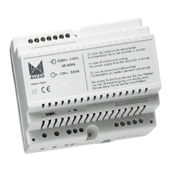
  • Page 29: Caractéristiques Techniques

    TCB-072 CAPTEUR: CCD Couleur 1/3” ILLUMINATION: Leds Blanches H: 60 ANGLE DE VISION: V: 45 ORIENTATION: TEMPÉRATURE DE TRAVAIL: -10.. +55 ALIMENTATION ALS-020 ALS-020 Tension: 230 V~ ±15% 50/60Hz ALIMENTATION DE RÉSEAU: Courant: 350 mA (max.) Tension: 18 V SORTIES: Courant: 2 A (max.)
  • Page 30 VIDEO PORTIER 2 FILS GROUPE PHONIQUE GRF-302 GRF-302 Tension: 12,5 - 18 V ALIMENTATION: Courant: 350 mA (max.) TEMPÉRATURE DE TRAVAIL: -10.. +55 TENSIONS USUELLES EN FONCTION DE L’ÉTAT DE L’ÉQUIPEMENT BORNES VEILLE TRAVAIL +,– 12,5 - 18 V B3, B2 12,5 - 18 V B5, B4 12,5 - 18 V...
  • Page 31 VIDEO PORTIER 2 FILS SOLUCIÓN DE PROBLEMAS Rien ne fonctionne La plaque de rue n’émet aucun son lors Vérifi ez si la LED de l’alimentation est éteinte. d’un appel Avec la LED éteinte : a) vérifi ez la tension du Vérifi...
  • Page 32: Declaration Of Conformity

    Manufacturer's Address: Pol. Ind. Arreche-Ugalde, 1 Apdo. 455 20305 IRÚN (Guipúzcoa) SPAIN declares that the product Model Number(s): ALS-020, GRF-302, MVC-130, SCM-150, TCB-072, RVE-014, RPS-011 Product Description: KITS Product Option(s): INCLUDING ALL OPTIONS is in conformity with: Safety: EN 60065:2002...

Ce manuel est également adapté pour:

Grf-302Mvc-130Scm-150Tcb-072Rve-014Rps-011