Alcad GRF-202 Mode D'emploi
Table des Matières
Liens rapides
D O O R
E N T R Y
S Y S T E M S
KITS SYSTEM WITH INTERNAL COMMUNICATION
ENTRANCE PANEL
TELEPHONE
INDEX
ELEMENTS AND DIMENSIONS..................................................................................................................................................2
GENERAL OPERATION OF THE DOOR ENTRY SYSTEM WITH INTERNAL COMMUNICATION.......................................................3
STANDARD INSTALLATION IN DETACHED HOUSE .....................................................................................................................5
STANDARD INSTALLATION IN SEMI-DETACHED HOUSE. INTERNAL COMMUNICATION BETWEEN DWELLINGS .........................7
INSTALLATION IN SEMI-DETACHED HOUSE. INTERNAL COMMUNICATION IN EACH DWELLING (KIT + 2 TELEPHONES) .............9
INSTALLATION OF ADDITIONAL ELEMENTS.............................................................................................................................11
INSTALLING INSTRUCTIONS ...................................................................................................................................................12
ADJUSTMENT INSTRUCTIONS.................................................................................................................................................17
TECHNICAL CHARACTERISTICS ...............................................................................................................................................18
TROUBLE SHOOTING .............................................................................................................................................................21
Table des Matières

Manuels Connexes pour Alcad GRF-202


Sommaire des Matières pour Alcad GRF-202
-
Page 1: Table Des Matières
D O O R E N T R Y S Y S T E M S KITS SYSTEM WITH INTERNAL COMMUNICATION ENTRANCE PANEL TELEPHONE INDEX ELEMENTS AND DIMENSIONS..............................2 GENERAL OPERATION OF THE DOOR ENTRY SYSTEM WITH INTERNAL COMMUNICATION............3 STANDARD INSTALLATION IN DETACHED HOUSE ........................5 STANDARD INSTALLATION IN SEMI-DETACHED HOUSE. -
Page 2: Elements And Dimensions
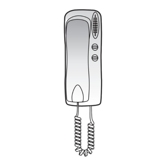
D O O R E N T R Y S Y S T E M S ELEMENTS AND DIMENSIONS Entrance panel Flush-mounted box. 1, 2 storeys. Surface box. 1, 2 storeys. Power supply Telephone for internal communication ENTRANCE PANEL - INSIDE MODULES Audio unit... -
Page 3: General Operation Of The Door Entry System With Internal Communication
D O O R E N T R Y S Y S T E M S GENERAL OPERATION OF THE DOOR ENTRY SYSTEM WITH INTERNAL COMMUNICATION MAKING A CALL FROM ONE TELEPHONE TO ANOTHER To call another telephone, pick up the receiver and press the second button on the telephone. MAKING A CALL TO A DWELLING FROM THE ENTRANCE PANEL Press the appropriate pushbutton on the entrance panel. - Page 4 D O O R E N T R Y S Y S T E M S RECEIVING A CALL FROM THE ENTRANCE PANEL TO A TELEPHONE WHICH IS COMMUNICATING WITH ANOTHER TELEPHONE If the telephone in the dwelling being called from the entrance panel is already communicating with another telephone, its receiver will emit several warning tones, allowing you to choose whether to speak to the visitor or to continue communicating with the other telephone.
-
Page 5: Standard Installation In Detached House
D O O R E N T R Y S Y S T E M S STANDARD INSTALLATION IN DETACHED HOUSE - SINGLE-WIRED DIAGRAM - SECTION TABLE Up to 50 m - Up to 25 m - Up to 100 m - Electric lock AC (Not included) Use separate cable hose Operation -... - Page 6 D O O R E N T R Y S Y S T E M S WIRED DIAGRAM - GRF-202 cod. 9610041 Electric lock AC (Not included) Use separate cable hose.
-
Page 7: Standard Installation In Semi-Detached House. Internal Communication Between Dwellings
D O O R E N T R Y S Y S T E M S STANDARD INSTALLATION IN SEMI-DETACHED HOUSE. INTERNAL COMMUNICATION BETWEEN DWELLINGS - SINGLE-WIRED DIAGRAM - Dwelling 1 Dwelling 2 SECTION TABLE Up to 50 m - Up to 25 m - Up to 100 m - Electric lock AC (Not included) - Page 8 D O O R E N T R Y S Y S T E M S WIRED DIAGRAM - Dwelling 1 Dwelling 2 GRF-202 cod. 9610041 Electric lock AC (Not included) Use separate cable hose.
-
Page 9: Installation In Semi-Detached House. Internal Communication In Each Dwelling (Kit + 2 Telephones)
D O O R E N T R Y S Y S T E M S INSTALLATION IN SEMI-DETACHED HOUSE. INTERNAL COMMUNICATION IN EACH DWELLING (KIT + 2 TELEPHONES) - SINGLE-WIRED DIAGRAM - Dwelling 1 Dwelling 2 SECTION TABLE Up to 50 m - Up to 25 m - Up to 100 m - Electric lock AC (Not included) - Page 10 D O O R E N T R Y S Y S T E M S WIRED DIAGRAM -...
-
Page 11: Installation Of Additional Elements
D O O R E N T R Y S Y S T E M S INSTALLATION OF ADDITIONAL ELEMENTS DOOR OPENING FROM INSIDE GRF-202 cod. 9610041 Push-button Push-button CONNECTION OF THE AUXILIARY PUSH-BUTTONS (TELEPHONE TIN-024) Terminals number 26, 27 and 28, 29 are potential-free contacts. To use them, take into account the following connection limitations: 50 mA - 12 Vdc. -
Page 12: Installing Instructions
D O O R E N T R Y S Y S T E M S I N S TA L L I N G I N S T R U C T I O N S RECOMMENDATIONS - When installing the entrance panel make sure that the sunrays or intense light sources do not fall directly on the video unit, avoiding nonwhished effects in picture display (backlight effect) and same way keeping the operational life of the equipment. - Page 13 D O O R E N T R Y S Y S T E M S ENTRANCE PANEL Lever open the cover of the card-holder and insert the card that identifies the pushbutton MOUNTING THE ENTRANCE PANEL IN A FLUSH-MOUNTED BOX Place the rings of the panel over the extracted fixing pins.
- Page 14 D O O R E N T R Y S Y S T E M S Make the electrical connections. See wired diagrams. Once the connection of the other components of the installation have been made, you will be able to make calls.
- Page 15 D O O R E N T R Y S Y S T E M S POWER SUPPLY Install the power supply unit in a dry, well-ventilated place away from direct sources of heat. Avoid blocking the ventilation slots. Protect the power supply unit by complying with existing regulations governing electrical installations (avoid high-temperature locations and strong magnetic fields, ensure correct fusing, etc.).
- Page 16 D O O R E N T R Y S Y S T E M S Cut the required perforated openings of the terminal cover. Fix it to the power supply unit using the fixing screws. TELEPHONE Remove the cover from D i s c o n e c t t h e c o r d the base of the telephone.
-
Page 17: Adjustment Instructions
D O O R E N T R Y S Y S T E M S ADJUSTMENT INSTRUCTIONS ENTRANCE PANEL Adjust the volume level on the entrance panel and Separate the upper and lower decorative fittings, on the telephones (1). by loosening the clamping screws. -
Page 18: Technical Characteristics
Note: Reference values are provided only to enable the checking of equipments and are reliable. Do not use the terminals of the equipments to feed additional devices without first consulting the manufacturer. ENTRANCE PANEL - AUDIO UNIT GRF-202 - Voltage Power supply... - Page 19 D O O R E N T R Y S Y S T E M S POWER SUPPLY ALA-020 Voltage Mains supply Power Voltage Output Current Operating temperature - TELEPHONE Internal communication TERMINALS AT REST WORKING Door entry system TERMINALS AT REST WORKING Audio max.
- Page 20 D O O R E N T R Y S Y S T E M S...
-
Page 21: Trouble Shooting
D O O R E N T R Y S Y S T E M S TROUBLE SHOOTING Check the connections between the different elements. Check The card holders don't light up. Check that the voltage between and V of the power the voltages in the different terminals (see “Technical supply is 12 ±... - Page 22 D O O R E N T R Y S Y S T E M S...
- Page 23 D O O R E N T R Y S Y S T E M S...
- Page 24 D O O R E N T R Y S Y S T E M S 06-02-07 Specifications subject to modifications without prior notice...