Table des Matières
Publicité
Les langues disponibles
Les langues disponibles
Liens rapides
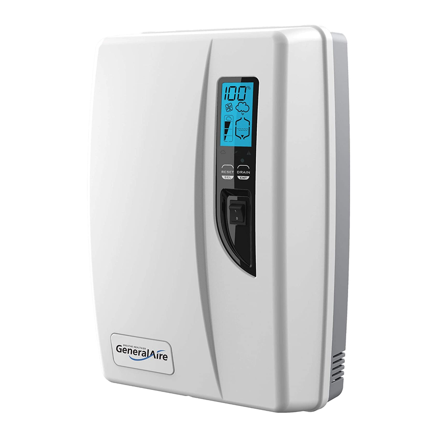
GeneralAire® 5500 Steam Humidifier
Installation & User Manual
Manuel d'installation et d'utilisation
Installation Kit and Mounting Straps are included.
Le kit d'installation et les sangles de fixation sont inclus.
Before installing or handling the humidifier, please carefully read and follow the instructions and safety
standards described within this manual and on the labels attached to the Model 5500 Steam Humidifier.
Test water conductivity before installing the Model 5500 Steam Humidifier.
Avant d'installer ou de manipuler l'humidificateur, veuillez lire attentivement et respecter les instructions et les
normes de sécurité décrites dans ce manuel et sur les étiquettes apposées sur l'humidificateur à vapeur modèle
5500. Testez la conductivité de l' e au avant d'installer l'humidificateur à vapeur modèle 5500.
User manual
Mode d'emploi
1
ENG
Form No. 5500-32 Rev C
Code: +0700092EN REV 3.2 04APR2022
READ AND SAVE
THESE INSTRUCTIONS
LISEZ ET ENREGISTREZ
CES INSTRUCTIONS
Publicité
Chapitres
Table des Matières
Dépannage

Manuels Connexes pour GeneralAire 5500


Sommaire des Matières pour GeneralAire 5500
- Page 1 Before installing or handling the humidifier, please carefully read and follow the instructions and safety standards described within this manual and on the labels attached to the Model 5500 Steam Humidifier. Test water conductivity before installing the Model 5500 Steam Humidifier.
-
Page 2: Before You Start
NTERNAL SWITCH: THE FACTORY DEFAULT SETTING IS 230 VAC; however, the humidifier can also be powered at a nominal voltage of 115 VAC 50/60 Hertz. Ensure the 5500’s internal power selection switch matches the power supplied to the 5500 (also described in this manual). - Page 3 Check packing slip to ensure all items have been received. Notify General Filters of any shortages or damaged parts. You must notify General Filters Form No. 5500-32 Rev C within 5 working days of any shortages. Code: +0700092EN REV 3.2 04APR2022...
-
Page 4: Table Des Matières
Contents 1. HOW IT WORKS Operating Stages ....................... 1 Cylinder Life ..........................2 Calculating Humidity Load.................... 3 2. MODEL INFORMATION 3. INSTALLATION Positioning ..........................5 Mounting / Dimensions and Weight ..............5 Fastening to the Wall......................6 Characteristics of the Supply Water ................. 7 Water Connections ...................... - Page 5 6. TROUBLESHOOTING 7. MAINTENANCE Periodic Checks ......................... 27 Cylinder Maintenance ....................27 Maintenance of Other Plumbing Components ........... 28 Replacement Parts......................28 8. TECHNICAL SPECIFICATIONS 9. LIMITED WARRANTY Form No. 5500-32 Rev C Code: +0700092EN REV 3.2 04APR2022...
-
Page 7: How It Works
NOTE: Any time the drain pump is activated, the OPERATING STAGES tempering valve ❾ will be opened for tempering the On a call for humidity, the 5500 Steam Humidifier (See Fig. 1.a.) hot drained water down to less than 140°F / 60°C in controller will: accordance to local and national standards. -
Page 8: Cylinder Life
Use only cold water since the supply water is used to temper the hot drain water. Water quality affects the operation of this unit, so the 5500 Steam Humidifier should be supplied with water that is untreated, drinkable, not softened, and not demineralized. -
Page 9: Calculating Humidity Load
* Based on .5 air charges per hour 5500 Steam humidifiers may be operated while construction Tab. 1.b is underway, but reduced cylinder life is to be expected. Good... -
Page 10: Model Information
CGF# DESCRIPTION PARTS INCLUDED 5580 GF-5500 Model 5500 steam unit features: Includes humidifier and duct steam mounting • 115V – 230V dual voltage kit components: 6 ft. steam hose, 8 inch steam • 125 – 1250 µS/cm water conductivity manifold, GFX4 humidistat, 10 ft. drain hose,... -
Page 11: Installation
MOUNTING / DIMENSIONS AND WEIGHT POSITIONING Removing the Front Cover The 5500 Steam Humidifier has been designed for wall The front cover is fastened by two tabs at the top and one mounting and since it is an electrode steam humidifier, screw located at the bottom center of the unit. -
Page 12: Fastening To The Wall
FASTENING TO THE WALL The 5500 Steam Humidifier can be installed on a finished wall or exposed studs per the following options: • Option 1: Attach directly to a wall using the supplied screws and anchors. Use the two inner holes of the supplied mounting strap as a template for the humidifier mounting holes (marked by “A”... -
Page 13: Characteristics Of The Supply Water
Softened water (will lead to foam, electrode corrosion and greatly shortened cylinder life) • Water containing disinfectants or corrosion inhibiters (potential irritants) • Industrial water, boiler water or water from cooling circuits • Any potentially chemically or bacteriologically-contaminated water • Heated water Form No. 5500-32 Rev C Code: +0700092EN REV 3.2 04APR2022... -
Page 14: Water Connections
Water Drain and Drain Hose The maximum allowed duct static pressure is 2 in. WC. The 5500 Steam Humidifier requires a connection to an open drain. A 10’ length of ¾” ID drain hose is included with unit. IMPORTANT: Allow 5 feet (1-1/2 M) of straight return duct... - Page 15 0 8 mm Important: DO NOT introduce steam 0 0.86” 0 22 mm 0 1.18 “ 0 30 mm into a duct that has interior insulation. Form No. 5500-32 Rev C Code: +0700092EN REV 3.2 04APR2022 0.87” 22 mm Tab. 3.d...
-
Page 16: Steam Manifold
Bottom Installation Side Installation Side Installation Horizontal Duct Horizontal Duct Vertical Duct min 8” 200 mm Air ow 1000 cfm min. Air ow min 8” 200 mm H > 8” Air ow 1000 cfm. min 24” min Upstream 36” min 1/3 height Downstream Air ow... -
Page 17: Steam Hoses
Use two 45° elbows instead of one 90° elbow. Hose inner diameter 7/8” (22 mm); Hose outer diameter 1¼” (30 mm). Additional steam hose is available GFI #7513 / CGF #GF-20-2. Form No. 5500-32 Rev C ROOM STEAM KIT Code: +0700092EN REV 3.2 04APR2022... -
Page 18: Power Supply Voltage Selection
3.10 POWER SUPPLY VOLTAGE SELECTION NOTE: Tolerance allowed on main voltage = - 15% to + 10%. The humidifier can be powered at either a nominal voltage of 115 Vac 50/60 Hertz or a nominal voltage of 230 Vac 50/60 Connect the ground wire to the unit’s chassis ground, located Hz. -
Page 19: Control Wiring
4.9 @ 115V 2.1@115V Tab. 3.e 3.12 CONTROL WIRING 5500 Steam Humidifiers allow for the connection of any simple G ND or automatic humidistat, safety devices such as a high limit humidistat, air flow proving switch, or remote ON/OFF switch). -
Page 20: Connect The Gfx4 Humidistat For On/Off Operation
Contact AB-AB: • Closed: humidifier enabled to produce steam (production starts when humidistat closes). JUMPER • Open: steam production is immediately stopped. G ND • The remote ON/OFF contact is usually a series of external potential-free contacts that enable the humidifier to produce G ND steam when all of them are closed, indicating the duct/AHU is ready to accept steam. -
Page 21: Furnace Blower Operation / Air Conditioner Relay Interlock
(FIELD SUPPLIED) 120V TRANSFORMER 24V, 10VA R W G Y HUMIDISTAT (FIELD SUPPLIED) NOTE: External transformer necessary because onboard transformer is not su cient to power auxiliary relay. Fig. 3.v Form No. 5500-32 Rev C Code: +0700092EN REV 3.2 04APR2022... -
Page 22: Wiring Connections
3.17 WIRING CONNECTIONS Terminals Functions Electrical Specifications L1-L2 Power supply and ground Power supply 115 VAC 1-phase 50-60Hz 1.86kW -GROUND connections or 230 VAC 1-phase 50-60Hz 4.05kW Programming port Connecting to programming port or supervisor Imposes an external NO contact; Rmax=300 Ohm; Vmax=33 Vdc; Imax=6mAdc; AB-AB Remote enabling input humidifier enabled = contact closed... -
Page 23: Wiring Diagram Of Controller
3.18 WIRING DIAGRAM OF CONTROLLER Always use AWG12 wires and dedicated 20A breaker for power supply connections to L1 / 2 in Fig. 3.w. Form No. 5500-32 Rev C Code: +0700092EN REV 3.2 04APR2022 Fig. 3.w... -
Page 24: Start Up
The 5500 Steam Humidifier is now ready to operate. When installation is completed, flush the supply pipe for • When there is a call for humidity, the 5500 Steam Humidifier 10 minutes by piping water directly into the drain without will close its power relays and send power to the electrodes sending it into the humidifier. -
Page 25: Controller Display
CONTROLLER DISPLAY The 5500 Steam Humidifier Controller features a comprehensive information display that shows the operation of the system at a glance: Location Description Display is % of nominal capacity Maintenance alarm Display is amperage (default) Steam is being produced... -
Page 26: Initial Configuration
2. Press and hold both buttons, “RESET/SEL” and “DRAIN/ • The unit can produce steam even if not config.d, but the ENTER”, and switch the 5500 Steam Humidifier back on. warning ‘EH’ will be shown on the display. When the wrench blinks then release the two buttons. - Page 27 Press and hold the “RESET/SEL” button until the value is 03 as shown on the display. Press “drain” for a minimum of 1 second to confirm. The hour counter will be reset once the unit resumes normal operation. Form No. 5500-32 Rev C Code: +0700092EN REV 3.2 04APR2022...
-
Page 28: Operating The Humidifier
2. Press and hold both “RESET/SEL” and “DRAIN/ENT” and and 139 hours. Once 1990 hours have elapsed (199 on the switch the 5500 Steam Humidifier back on. When the display), the hours are displayed in hundreds. Example: 21 wrench blinks, release the two buttons. -
Page 29: Changing The Maximum Production
5. Press “RESET/SEL” to change signal type between 0 and 1: AUTO mode: 0 = On-Off humidistat such as the GeneralAire® “M” or The GFX4 will automatically raise the humidity as the outdoor “GFX” series humidistat. temperature increases to provide the highest possible 1 = external 0...10 Vdc modulating signal such as the... - Page 30 To change the temperature unit: Press °C / °F. To set the temperature / humidity offset in MANUAL or AUTO mode: ▲ ▼ 1. Simultaneously press when viewing the temperature or humidity reading. ▲ ▼ 2. Use to change the setting to be -5 to 5. ▲...
-
Page 31: Alarms
High controller tem- The warning is automatically Check the ambient temperature, replace perature (above 176°F reset if the temperature de- the controller / 80°C) creases below 176 °F / 80 °C Form No. 5500-32 Rev C Code: +0700092EN REV 3.2 04APR2022... -
Page 32: Troubleshooting
Tab. 5.d 6. TROUBLESHOOTING PROBLEM CAUSE SOLUTION No electrical power Check the safety devices upstream from the humidifier and the ON/OFF switch of the humidifier presence of power The humidifier in position 0 (open) Close the switch on the panel: position I does not turn on Control connectors improperly connected Check that connectors are properly inserted in terminal block... -
Page 33: Maintenance
The life of the cylinder depends on a number of factors, as operation and void the warranty. previously described. As previously mention in this manual, maximum production can shorten cylinder life. Since the 5500 To Replace the Cylinder: is pre-set from the factory at 100%, reducing the factory setting 1. -
Page 34: Maintenance Of Other Plumbing Components
7. Install the new cylinder in the humidifier by performing Cleaning the Drain Pump the previous operations in reverse. • Remove the valve body, clean if necessary, using the same • Connect the power cables to the electrodes in the cleaning solution as for the steam cylinder and a soft brush. -
Page 35: On/Off Switch
7747 GF-5500-03 5500-03 CONTROL MODULE ASSEMBLY 115V/230V 7551 GF-35-18 35-18 ON/OFF SWITCH 7753 GF-5500-08 5500-08 FILL & DRAIN TEMPERING VALVE 230V 7805 GF-25-7 25-7 KIT FOR DRAIN PUMP 230V 7806 GF-25-2 25-2 FILL TANK + PLUG FOR DRAIN PUMP 7810... -
Page 36: Technical Specifications
8. TECHNICAL SPECIFICATIONS SPECIFICATION DESCRIPTION NOTES 4.9 lbs/hr (2.2 kg/h) / 115 VAC 1-phase 50-60 Hz / 1.86 kW Capacity / VAC / kW 9.9 lbs/hr (4.5 kg/h) / 230 VAC 1-phase 50-60 Hz / 4.05 kW Steam pressure 3.81 in WC / 950 Pa (.137 PSI) Dimensions (inches / mm) 21”... - Page 37 Form No. 5500-32 Rev C Code: +0700092EN REV 3.2 04APR2022...
- Page 38 NOTES:...
- Page 39 Form No. 5500-32 Rev C Code: +0700092EN REV 3.2 04APR2022...
-
Page 40: Limited Warranty
9. LIMITED WARRANTY GeneralAire® Model 5500 Steam Humidifiers, if properly registered on www.generalfilters.com/support/warranty-registration, are warranted to the consumer against defects in materials and workmanship for a period of five years from the date of installation, so long as the product has been installed by a qualified contractor and operated in accordance with all appropriate manuals and wiring diagrams in a residential structure. - Page 41 Form No. 5500-32 Rev C Code: +0700092EN REV 3.2 04APR2022 400 Midwest Rd. Toronto, ON M1P 3A9 Our Brands Canada Toll Free: (888) 216-9184 ® www.generalaireiaq.ca sales@generalaireiaq.ca Last Updated: 04-2022...
- Page 43 Mode d’emploi Form No. 5500-32 Rev C Code: +0700092EN REV 3.2 04APR2022...
-
Page 44: Avant De Commencer
également être alimenté à une tension nominale de 115 VCA 50/60 Hertz. Assurez-vous que le commutateur de sélection d’alimentation interne du 5500 correspond à l’alimentation fournie au 5500 (également décrit dans ce manuel). 2. PANNEAU DE COMMANDE - AU DÉMARRAGE INITIAL : LE RÉGLAGE D’USINE PAR DÉFAUT EST LE RÉGLAGE N° 3 (230V/11A), si aucune sélection n‘est effectuée. -
Page 45: Avertissements
Ouvrez les cartons et vérifiez s’il y a des dommages pièces doivent être éliminées conformément aux normes locales cachés. Marquez le bordereau d’expédition en d’élimination des déchets. conséquence. • Vérifiez le bordereau d’expédition pour vous assurer Formulaire n . 5500-32 Rev C Code: +0700092EN REV 3.2 04APR2022... - Page 46 Contents 1. COMMENT CELA FONCTIONNE Étapes de fonctionnement ..................1 Durée de vie du cylindre ....................2 Calcul de la charge d'humidité ................... 3 2. INFORMATIONS SUR LE MODÈLE 3. INSTALLATION Positionnement ........................5 Montage / Dimensions et poids ................5 Fixation au mur ........................
- Page 47 7. MAINTENANCE Contrôles périodiques ....................27 Maintenance du cylindre .................... 27 Maintenance des autres éléments de plomberie ........28 Pièces de rechange ......................29 8. SPÉCIFICATIONS TECHNIQUES 9. GARANTIE LIMITÉE Formulaire n . 5500-32 Rev C Code: +0700092EN REV 3.2 04APR2022...
-
Page 49: Comment Cela Fonctionne
à vapeur ❺. Tout reflux ou débordement d'eau passe par le tuyau de Si l’humidificateur à vapeur 5500 reste sous tension mais ⓫ débordement jusqu’à... -
Page 50: Durée De Vie Du Cylindre
La qualité de l’eau a une incidence sur le fonctionnement de cet appareil. L’humidificateur à vapeur 5500 doit donc être alimenté en eau non traitée, potable, non adoucie et non déminéralisée. L’eau transformée en vapeur est automatiquement remplacée via une vanne de remplissage électrique. -
Page 51: Calcul De La Charge D'humidité
• Maison de 2 500 pi2 avec sous-sol de 1 000 pi2 (superficie être cinq à huit fois plus élevée que lorsqu’elle est finie. Les totale de 3 500 pi2) humidificateurs à vapeur 5500 peuvent être utilisés pendant • Plafond de 9 pi les travaux de construction, mais il faut s’attendre à une •... -
Page 52: Informations Sur Le Modèle
2. INFORMATIONS SUR LE MODÈLE Modèle 5500 Ensemble d’installation (fourni) Fig. 2.b Ensemble d’humidification d’ambiance RMB15/RMB35 (En option et vendus séparément) Fig. 2.a Fig. 2.c N° GFI CGF# DESCRIPTION PIÈCES INCLUSES 5580 GF-5500 Caractéristiques de l’humidificateur Comprend les composants du kit de montage de modèle 5500 :... -
Page 53: Installation
MONTAGE / DIMENSIONS ET POIDS Retrait du capot frontal L’humidificateur à vapeur 5500 a été conçu pour être installé au mur et, puisqu’il s’agit d’un humidificateur à vapeur à Le capot avant est fixé par deux languettes en haut et une électrode, il doit être placé... -
Page 54: Fixation Au Mur
FIXATION AU MUR L’humidificateur à vapeur 5500 peut être installé sur un mur fini ou sur des montants exposés selon les options suivantes : • Option 1 Fixez directement à un mur à l’aide des vis et des ancrages fournis. Utilisez les deux trous intérieurs de la sangle de montage fournie comme modèle pour les trous de montage de l’humidificateur (marqués « A »... -
Page 55: Caractéristiques De L'eau D'alimentation
Eau contenant des désinfectants ou des inhibiteurs de corrosion (irritants potentiels) • Eau industrielle, eau de chaudière ou eau des circuits de refroidissement • Toute eau potentiellement contaminée chimiquement ou bactériologiquement. • Eau chauffée Formulaire n . 5500-32 Rev C Code: +0700092EN REV 3.2 04APR2022... -
Page 56: Raccordements D'eau
Collecteur de vapeur de 8 po (compris) constante (ne peut être plié, bloqué ou créer un piège) et peut L’humidificateur à vapeur modèle 5500 est fourni en standard être acheminé directement vers un siphon de sol, une pompe à avec un collecteur de vapeur de 8 po. Une buse à vapeur et des condensat ou une canalisation d’évacuation. - Page 57 Important: N’introduisez PAS de vapeur dans un conduit 0 0,31 0 8 mm doté d’un isolant intérieur. 0 0,86 po 0 22 mm 0 1,18 po 0 30 mm 0,87 po 22 mm Tab. 3.d Formulaire n . 5500-32 Rev C Code: +0700092EN REV 3.2 04APR2022...
-
Page 58: Collecteur À Vapeur (Options De 12 Et 17,5 Pouces Disponibles)
Bottom Installation Side Installation Side Installation Horizontal Duct Horizontal Duct Vertical Duct min 8” 200 mm Air ow 1000 cfm min. Air ow min 8” 200 mm H > 8” Air ow 1000 cfm. min 24” min Upstream 36” min 1/3 height Downstream Air ow... -
Page 59: Tuyau À Vapeur
7/8 po (22 mm); diamètre extérieur du tuyau 1 ¼ po (30 mm). Un tuyau à vapeur supplémentaire est disponible GFI #7513 / CGF #GF-20-2. ENSEMBLE D'HUMIDIFICATION D'AMBIANCE Référez-vous aux instructions incluses dans l’ensemble d'humidification d'ambiance RMB15 (115 V) / RMB35 (230 V). Formulaire n . 5500-32 Rev C Code: +0700092EN REV 3.2 04APR2022... -
Page 60: Sélection De La Tension D'alimentation
3.10 SÉLECTION DE LA TENSION REMARQUE : Tolérance autorisée sur la tension principale = - D'ALIMENTATION 15 % à + 10 %. L’humidificateur peut être alimenté soit par une tension Connectez le fil de terre à la masse du châssis de l'appareil, nominale de 115 V CA 50/60 Hertz, soit par une tension située juste derrière le bloc de raccordement du câblage nominale de 230 V CA 50/60 ... -
Page 61: Câblage De Commande
4,9 @ 115 V 2,1 @ 115 V Tab. 3.e 3.12 CÂBLAGE DE COMMANDE Les humidificateurs à vapeur 5500 permettent le raccordement G ND de n’importe quel hygrostat simple ou automatique, de dispositifs de sécurité tels qu’un hygrostat à limite élevée, un interrupteur de contrôle du débit d’air ou un interrupteur ON/... -
Page 62: Connecter L'hygrostat Gfx4 Pour L'opération On/Off
Contact AB-AB : • Fermé : humidificateur permettant de produire de la vapeur JUMPER (la production commence lorsque l’hygrostat se ferme). • Ouvert : la production de vapeur s’arrête immédiatement. G ND • Le contact ON/OFF à distance est habituellement une série de contacts externes sans potentiel qui permettent à G ND l’humidificateur de produire de la vapeur lorsqu’ils sont tous fermés, ce qui indique que le conduit est prêt à... -
Page 63: Fonctionnement Du Ventilateur De L'appareil De Chauffage / Verrouillage Du Relais Du Climatiseur
(FIELD SUPPLIED) 120V TRANSFORMER 24V, 10VA R W G Y HUMIDISTAT (FIELD SUPPLIED) NOTE: External transformer necessary because onboard transformer is not su cient to power auxiliary relay. Fig. 3.v Formulaire n . 5500-32 Rev C Code: +0700092EN REV 3.2 04APR2022... -
Page 64: Branchements Des Câbles
3.17 BRANCHEMENTS DES CÂBLES Bornes Fonctions Spécifications électriques L1-L2-MISE Connexions d’alimentation Alimentation électrique 110 V CA monophasée 50-60 Hz À TERRE électrique et de mise à terre 1,86 kW ou 230 V CA monophasée 50-60 Hz 4,05 kW TOUCHE Porte de programmation Connexion à la porte de Programmation ou superviseur Imposer un contact NO externe ;... -
Page 65: Schéma De Câblage Du Contrôleur
3.18 SCHÉMA DE CÂBLAGE DU CONTRÔLEUR Utilisez toujours des fils AWG12 et un disjoncteur 20 A dédié pour les connexions d’alimentation à L1 / 2 dans la Fig. 3.w. Fig. 3.w Formulaire n . 5500-32 Rev C Code: +0700092EN REV 3.2 04APR2022... -
Page 66: Mise En Marche
• Lors d’une demande d’humidité, l’humidificateur à vapeur pendant 10 minutes environ en faisant couler l’eau 5500 fermera ses relais d’alimentation et enverra du courant directement dans l’évacuation, sans raccorder la tuyauterie à aux électrodes dans le générateur de vapeur en plastique. -
Page 67: Affichage Du Contrôleur
AFFICHAGE DU CONTRÔLEUR Le contrôleur d’humidificateur à vapeur 5500 est doté d’un écran d’information complet qui permet de visualiser le fonctionnement du système d’un seul coup d'œil : Emplacement Description Affiche la capacité nominale en % Alarme de maintenance Affiche l’ampérage (par défaut) -
Page 68: Configuration Initiale
• Si aucune sélection n'est effectuée dans les 10 secondes, “DRAIN/ENTER”, et remettez l’humidificateur à vapeur l’unité commencera à utiliser le réglage par défaut de 5500 en marche. Lorsque la clé à molette clignote, l’Option 3. L’unité peut être configurée à nouveau lors relâchez les deux boutons. - Page 69 03 comme indiqué sur l’écran. Appuyez sur « drainer » pendant au moins 1 seconde pour confirmer. Le compteur horaire sera réinitialisé une fois que l’unité reprendra son fonctionnement normal. Formulaire n . 5500-32 Rev C Code: +0700092EN REV 3.2 04APR2022...
-
Page 70: Utilisation De L'humidificateur
2. Maintenez enfoncés les deux boutons, « RESET/SEL » et (il doit être remis à zéro à chaque remplacement du « DRAIN/ENT », et remettez l’humidificateur à vapeur 5500 cylindre). Par exemple, si le cylindre a fonctionné pendant en marche. Lorsque la clé à molette clignote, relâchez les 100 heures à... -
Page 71: Modification De La Production Maximale
. L’indice d’humidité est basé sur la 5 %, afin de s’adapter aux caractéristiques environnementales. température extérieure et l’humidité intérieure. L’humidificateur à vapeur 5500 est réglé à 100 % en usine. L’humidificateur s’allume/s’éteint selon le point de consigne 1. Mettre l’humidificateur à vapeur hors tension. - Page 72 PARAMÈTRE SUGGÉRÉ TEMPÉRATURE EXTÉRIEURE -20˚ F / -29˚ C -10˚ F / -23˚ C 0˚ F / -18˚ C +10˚ F / -12˚ C 35 % +20˚ F / -7˚ C +30˚ F / -1˚ C Tab. 5.c REMARQUE : Si le capteur de température extérieure échoue, clignote et l’unité passera en mode MANUEL. Pour basculer entre température extérieure / intérieure et humidité...
-
Page 73: Alarmes
Température du contrôl- tiquement si la température Contrôlez la température am- eur élevée (supérieure à descend en dessous de 80 °C / biante, remplacez le contrôleur 176 °F / 80 °C) 176 °F. Tab. 5.d Formulaire n . 5500-32 Rev C Code: +0700092EN REV 3.2 04APR2022... -
Page 74: Dépannage
6. DÉPANNAGE PROBLÈME CAUSE SOLUTION Contrôler les dispositifs de sécurité en amont de l’humidificateur Absence d’alimentation électrique et la présence d’électricité L’interrupteur On/off de l’humidificateur Fermer l’interrupteur sur le Tableau : position I L’humidificateur est sur 0 (ouvert) Contrôler que les connecteurs sont bien insérés dans les ne s’allume pas. -
Page 75: Contrôles Périodiques
Étant donné que 1. Vidangez complètement le ballon en maintenant enfoncée le 5500 est préréglé en usine à 100 %, la réduction du réglage la touche « DRAIN » jusqu’à ce que le ballon soit vide;... -
Page 76: Maintenance Des Autres Éléments De Plomberie
remplacement du joint torique, retirez-le avec précaution à et une brosse douce, puis en rinçant abondamment à l'eau l’aide d’un petit tournevis. N’essayez pas de retirer la bague douce les éléments de la plomberie (pompe de vidange, du joint torique en plastique ou elle sera endommagée et vanne remplissage/température, connecteur... -
Page 77: Pièces De Rechange
MODULE DE COMMANDE 115 V/230 V 5500-03 7551 GF-35-18 BOUTON MARCHE/ARRÊT 35-18 7753 GF-5500-08 VANNE DE RÉGULATION DE REMPLISSAGE ET DE VIDANGE 230 V 5500-08 7805 GF-25-7 KIT POUR POMPE DE VIDANGE 230 V 25-7 7806 GF-25-2 RÉSERVOIR DE REMPLISSAGE + BOUCHON POUR POMPE DE VIDANGE 25-2... -
Page 78: Spécifications Techniques
8. SPÉCIFICATIONS TECHNIQUES SPÉCIFICATIONS DESCRIPTION NOTES 4,9 lbs/hr (2,2 kg/h) / 115 VCA monophasé 50-60 Hz / 1,86 kW Capacité / VCA / kW 9,9 lbs/hr (4,5 kg/h) / 230 VCA monophasé 50-60 Hz / 4,05 kW Pression vapeur 3,81 in WC / 950 Pa (.137 PSI) Dimensions (pouces / mm) 21 po H x 13 po L x 8,25 po P / 533 mm H x 343 mm L x 210 mm P Poids à... - Page 79 Formulaire n . 5500-32 Rev C Code: +0700092EN REV 3.2 04APR2022...
-
Page 80: Garantie Limitée
9. GARANTIE LIMITÉE Les humidificateurs à vapeur GeneralAire® modèle 5500, s’ils sont correctement enregistrés sur www.generalfilters.com/support/ warranty-registration, sont garantis au consommateur contre tout défaut de matériaux et de fabrication pour une période de cinq ans à compter de la date d'installation, à condition que le produit ait été installé par un entrepreneur qualifié et utilisé... - Page 81 NOTES : Formulaire n . 5500-32 Rev C Code: +0700092EN REV 3.2 04APR2022...
- Page 82 400 Midwest Rd. Toronto, ON M1P 3A9 Our Brands Canada Toll Free: (888) 216-9184 ® www.generalaireiaq.ca sales@generalaireiaq.ca Last Updated: 04-2022...