Table des Matières
Publicité
Les langues disponibles
Les langues disponibles
Liens rapides
M
ANUALE UTENTE
C
USTOMER MANUAL
M
ANUAL DEL CLIENTE
M
ANUEL DU CLIENT
B
ENUTZERHANDBUCH
G
EBRUIKERS HANDBOEK
Nome file:
7528001 - ISTRUZIONI WP - IT-EN-ES-FR-DE-NL-ES
File name:
WP14000 – WP14000-T
WP16000 – WP16000-T
WP19000 – WP19000-T
WP21000 – WP21000-T
(IT)
(EN)
(ES)
(FR)
(DE)
(NL)
1-102
M
ANUALE INSTALLATORE
I
NSTALLATION MANUAL
M
ANUAL DE LA INSTALACIÓN
M
'
ANUEL D
INSTALLATION
I
NSTALLATION HANDBUCH
I
NSTALLATIE HANDBOEK
(IT)
(EN)
(ES)
(FR)
(DE)
(NL)
Rev. 0 05/10/2015
Publicité
Table des Matières
Dépannage

Manuels Connexes pour Steinbach WP 14000


Sommaire des Matières pour Steinbach WP 14000
- Page 1 WP14000 – WP14000-T WP16000 – WP16000-T WP19000 – WP19000-T WP21000 – WP21000-T (IT) (IT) ANUALE UTENTE ANUALE INSTALLATORE (EN) (EN) USTOMER MANUAL NSTALLATION MANUAL (ES) (ES) ANUAL DEL CLIENTE ANUAL DE LA INSTALACIÓN (FR) (FR) ANUEL DU CLIENT ANUEL D INSTALLATION (DE) (DE)
- Page 2 Nome file: 7528001 - ISTRUZIONI WP - IT-EN-ES-FR-DE-NL-ES Rev. 0 05/10/2015 File name: 2-102...
-
Page 3: Table Des Matières
I N D E X Presentazione dell’organizzazione del contenuto e modalità di consultazione........9 Simbologia............................. 9 Note sull’esposizione grafica......................9 Glossario............................9 Avvertenze generali e informazioni al destinatario................10 Garanzia............................10 2.1.1 Aspetti generali........................10 2.1.2 Condizioni particolari. - Page 4 I N D E X Glossary............................24 General warnings and user information....................24 Warranty............................24 2.1.1 General aspects........................24 2.1.2 Special conditions......................... 25 2.1.3 Restrictions........................... 25 Returns............................25 General and safety warnings......................25 2.3.1 General warnings.
- Page 5 I N D E X 2.1.2 Condiciones especiales......................40 2.1.3 Limitaciones.......................... 40 Modalidad de entrega........................41 Advertencias generales y de seguridad..................41 2.3.1 Advertencias generales......................41 2.3.2 Advertencias de seguridad....................41 Contactos y direcciones útiles...................... 42 Presentación del producto.
- Page 6 I N D E X 2.3.1 Avertissements généraux...................... 56 2.3.2 Consignes de sécurité......................56 Contacts et adresses utiles......................57 Présentation de l’appareil........................57 Emploi de l’appareil........................57 Composition..........................57 Données et caractéristiques techniques....................57 Montage.
- Page 7 I N D E X Zweck des Produkts........................73 Zusammensetzung........................73 Technische Daten und Eigenschaften....................73 Installation............................74 Notwendige Werkzeuge....................... 74 Eigenschaften und Bedingungen der Lagerung................74 Transport............................74 Bewegung............................ 74 Aufstellung........................... 75 Anschluss und Inbetriebnahme.
- Page 8 I N D E X Noodzakelijk gereedschap......................90 Eigenschappen en opslagvoorwaarden..................90 Transport............................90 Verplaatsing..........................90 Plaatsing............................91 Aansluiting en inbedrijfstelling...................... 92 5.6.1 Installatie van de batterij....................... 93 5.6.2 De verbinding van de slang....................94 5.6.3 Aanzuigen.
-
Page 9: Presentazione Dell'organizzazione Del Contenuto E Modalità Di Consultazione
( V E R S I O N E O R I G I N A L E / O R I G I N A L V E R S I O N ) Presentazione dell’organizzazione del contenuto e modalità di consultazione. 1.1 Simbologia. -
Page 10: Avvertenze Generali E Informazioni Al Destinatario
( V E R S I O N E O R I G I N A L E / O R I G I N A L V E R S I O N ) 26. Spazio libero necessario: dimensioni minime dello spazio di installazione del prodotto. Avvertenze generali e informazioni al destinatario. -
Page 11: Avvertenze Di Sicurezza
( V E R S I O N E O R I G I N A L E / O R I G I N A L V E R S I O N ) SHOTT International srl declina ogni responsabilità per qualsiasi danno derivante da un uso improprio del prodotto. -
Page 12: Presentazione Del Prodotto
( V E R S I O N E O R I G I N A L E / O R I G I N A L V E R S I O N ) Presentazione del prodotto. 3.1 Finalità del prodotto. Il prodotto che avete acquista è... -
Page 13: Installazione
( V E R S I O N E O R I G I N A L E / O R I G I N A L V E R S I O N ) n=2850 [min WP21000 WP21000-T WP19000 WP16000 WP14000 WP19000-T... -
Page 14: Posizionamento
( V E R S I O N E O R I G I N A L E / O R I G I N A L V E R S I O N ) 5.5 Posizionamento. Il prodotto deve essere posizionato sottobattente. Fig. -
Page 15: Allacciamento E Messa In Servizio
( V E R S I O N E O R I G I N A L E / O R I G I N A L V E R S I O N ) Fig. 14 • Supporto e sua ubicazione. Nel caso di utilizzo del prodotto con un filtro è... -
Page 16: Installazione Della Batteria
( V E R S I O N E O R I G I N A L E / O R I G I N A L V E R S I O N ) Il prodotto va collegato ad una presa elettrica dotata di interruttore differenziale di sicurezza, con sensibilità... -
Page 17: Connessione Dei Tubi
( V E R S I O N E O R I G I N A L E / O R I G I N A L V E R S I O N ) Fig. 22 5.6.2 Connessione dei tubi. Procedere come segue: 1. -
Page 18: Reinstallazione E Riutilizzazione
( V E R S I O N E O R I G I N A L E / O R I G I N A L V E R S I O N ) Fig. 25 Fig. 26 5.7 Reinstallazione e riutilizzazione. Pulire accuratamente il prodotto e le parti in movimento prima di un periodo di inattività... -
Page 19: Descrizione Del Funzionamento
( V E R S I O N E O R I G I N A L E / O R I G I N A L V E R S I O N ) Per scollegare il prodotto dalla rete elettrica, estrarre la spina elettrica dalla presa elettrica, non tirare il cavo di alimentazione. -
Page 20: Verifica Di Funzionamento Della Spina Elettrica Con Interruttore Differenziale
( V E R S I O N E O R I G I N A L E / O R I G I N A L V E R S I O N ) La spina elettrica con interruttore differenziale non sostituisce i componenti di sicurezza elettrica obbligatori: l’impianto elettrico deve essere conforme alle norme internazionali e/o nazionali vigenti, se necessario rivolgersi a personale tecnico specializzato. -
Page 21: Manutenzione Ordinaria
( V E R S I O N E O R I G I N A L E / O R I G I N A L V E R S I O N ) • Le vibrazioni del prodotto. In caso di anomalia, arrestare immediatamente il prodotto e rivolgersi a personale tecnico specializzato. - Page 22 ( V E R S I O N E O R I G I N A L E / O R I G I N A L V E R S I O N ) PROBLEMA POSSIBILE CAUSA 1° SOLUZIONE 2°...
-
Page 23: Componenti Commerciali, Ricambi E Relativa Documentazione
( V E R S I O N E O R I G I N A L E / O R I G I N A L V E R S I O N ) 10 Componenti commerciali, ricambi e relativa documentazione. Sostituire i componenti danneggiati e/o deteriorati nel più... -
Page 24: Content Organisation And Consultation Methods
Content organisation and consultation methods. 1.1 Symbols. Indicates hazardous situations and warnings. Carefully read the parts of the user manual marked with this symbol. Indicates that work must not be performed on live electrical devices. This work may only begin after all suitable safety measures required by current international and/or national regulations are taken. -
Page 25: Special Conditions
iii. If a product compliance defect is found and the purchaser informs the dealer during the warranty period, the dealer must repair or replace the product at his own expense and where he deems most suitable, unless impossible or incommensurate. iv. -
Page 26: Safety Warnings
2.3.2 Safety warnings. This product can be used by children aged from 8 years and above and person with reduced physical, sensory or mental capabilities or lack of experience and knowledge if they have been given supervision or instruction concerning use of the product in a safe way and understand the hazards involved. -
Page 27: Product Presentation
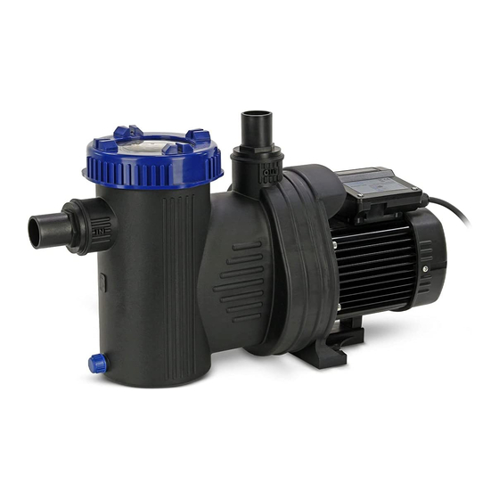
Product presentation. 3.1 Product scope. product purchased centrifugal pool pump designed to pump fresh and salt water. 3.2 Composition. Hosetail O-ring Draining tap Frame Lock nut Cover Prefilter Impeller Rubber Flange Carter Power cord Capacitor Fig. 42 Cover Technical specifications and features. The hydraulic parts used for the building of the system which shall include the product modify the performance (head and flowrate) of the product. -
Page 28: Installation
n=2850 [min WP21000 WP21000-T WP19000 WP16000 WP14000 WP19000-T WP16000-T WP14000-T Q [m Fig. 43 WP14000-T WP14000 WP16000-T WP16000 WP19000-T WP19000 WP21000-T WP21000 Fig. 44 Installation. 5.1 Necessary tools. Phillips Fig. 45 5.2 Storage features and conditions. Store the product in a dry place and keep away from the elements. Storage temperature: -10 [°C] (+14 [°F]) to +60 [°C] (+140 [°F]). -
Page 29: Positioning
5.5 Positioning. The product must be positioned under head. Fig. 46 The product must be placed in an area not subject to flooding. Fig. 47 The product cannot be used on the water surface. The product must always be located at least 3.5 [m] from the edge of the swimming pool from which water is drawn. -
Page 30: Connections And Start-Up
Fig. 50 • Support and its location. If the product is used with a filter, the latter must be downstream from the product. Fig. 51 If the product is placed outside it is advisable to put a simple cover to protect it from rain. Make sure the product is positioned in a place where noise generated during normal operations does not create disturbances. -
Page 31: Battery Installation
Make sure the product complies with your electrical system. The power outlet must be at a suitable distance from the water but easily accessible in order to be able to easily turn off the product in the event of fault (electrical socket, at least 3,5 [m] from the edge of the pool). -
Page 32: Hose Connection
Fig. 58 5.6.2 Hose connection. Proceed as follows: 1. Position the O-rings (Fig. 59, # A) on the rubber holder (Fig. 59, # B). 2. Screw the two rubber holders in (Fig. 59) on the inlet and outlet side of the pump. 32 mm 38 mm 38 mm... -
Page 33: Reinstallation And Reuse
5.7 Reinstallation and reuse. Clean the product and the moving parts accurately before stopping the product for a while, such as, for instance, during the winter months. Do not lubricate and/or use detergents and chemical cleaning products. If there is the risk of freezing, the product must be carefully emptied from the liquids in its hydraulic circuit. -
Page 34: Hazards And Risks
6.6 Hazards and risks. Attention to the inlet/outlet points because they can trap parts of the body and/or hair and cause serious personal injuries and even death. Pumps, filters, and other equipment/components of a pool filtration system can operate under pressure. If not correctly installed they can cause serious personal injuries and even death. -
Page 35: Routine, Scheduled And Extraordinary Maintenance
7.2.1.1 Timer settings. Proceed as follows: 1. Turn the product off by pressing the ON/OFF button. 2. Press TIMER to select the operating time (2, 4, 6, 8, 10, 12, 16, 24 operating hours). 3. Press the ON/OFF button to turn the product on. Example: set 8 operating hours, if the product is turned on at 8 AM: the product will operate until 4 PM. - Page 36 ROBLEM AUSE OLUTION OLUTION Contact specialised 5. Power cord damaged. Wear and/or negligence. technicians. 6. Plastic components Contact specialised Wear. Replace. damaged. technicians. 7. Low flowrate from Contact specialised The product is dirty Clean the product. outlet technicians. 8. Low flowrate from Hydraulic components Clean and adjust Contact specialised...
- Page 37 Fig. 71 Nome file: 7528001 - ISTRUZIONI WP - IT-EN-ES-FR-DE-NL-ES Rev. 0 05/10/2015 File name: 37-102...
-
Page 38: Retail And Spare Parts And Relevant Documentation
10 Retail and spare parts and relevant documentation. Replace any damaged and/or worn components as quickly as possible; use only original spare parts. Battery: CR2032 Fig. 72 XQ708I13 XQ710I13 XQ700I13 XQ709I13 XQ711I10 (Ø 32/38[mm]) XQ711I20 (Ø 38[mm]) XQ712I13 XQ713I13 XQ714I13 XQ714I23 XQ714I33 XQ714I43... -
Page 39: Presentación De La Organización Del Contenido Y Modalidad De Consulta
Presentación de la organización del contenido y modalidad de consulta. Indica situaciones de peligro y advertencias. Es necesario leer con la máxima atención las partes del manual del cliente marcadas con este símbolo. Indica que no deben efectuarse trabajos en aparatos eléctricos bajo tensión. Dichos trabajos pueden comenzar solo cuando se hayan tomado las medidas de seguridad adecuadas, prescritas por las normas internacionales y/o nacionales vigentes. -
Page 40: Advertencias Generales E Informaciones Para El Destinatario
22. Presión de funcionamiento máxima: presión máxima que el producto es capaz de sostener durante el funcionamiento. 23. Herramienta: destonillador, moneda u otro objeto, que se pueda usar para manipular un tornillo o un dispositivo de fijación similar. 24. Espacio libre necesario: dimensiones mínimas del espacio de instalación del producto. -
Page 41: Modalidad De Entrega
2.2 Modalidad de entrega. En caso de defectos, problemas y mal funcionamiento el producto debe entregarse al vendedor con un cartel que indique la falta de conformidad, cuando esté presente, adecuadamente rellenado. 2.3 Advertencias generales y de seguridad. 2.3.1 Advertencias generales. SHOTT International srl trabaja continuamente para mejorar los productos. -
Page 42: Contactos Y Direcciones Útiles
graves o incluso la muerte. Los materiales de embalaje no son juguetes para niños, las películas de protección pueden ser peligrosas y causar un ahogamiento. No utilizar la piscina en caso en que el producto (filtro/bomba) sea inutilizable. Si el cable de alimentación está dañado, el mismo debe ser sustituido por el revendedor o por su servicio de asistencia técnica o, en todo caso, por una persona con cargo similar, de manera tal de prevenir cualquier riesgo (personal técnico especializado). -
Page 43: Instalación
n=2850 [min WP21000 WP21000-T WP19000 WP16000 WP14000 WP19000-T WP16000-T WP14000-T Q [m Fig. 79 WP14000-T WP14000 WP16000-T WP16000 WP19000-T WP19000 WP21000-T WP21000 Fig. 80 Instalación. 5.1 Utensilios necesarios. Phillips Fig. 81 5.2 Características y condiciones de almacenamiento. Durante el almacenamiento guardar el producto en un lugar seco y al resguardo de la intemperie. Temperatura de almacenamiento: -10 [°C] (+14 [°F]) a +60 [°C] (+140 [°F]). -
Page 44: Posicionamiento
5.5 Posicionamiento. El producto debe ser posicionado inundado. Fig. 82 El producto debe ser colocado en una zona no sujeta a inundaciones. Fig. 83 No se puede utilizar el producto sobre la superficie del agua. El producto debe ser colocada siempre a por lo menos 3,5 [m] del borde de la piscina de donde se toma el agua. -
Page 45: Conexión Y Puesta En Servicio
Fig. 86 • Soporte y su ubicación. En el caso de uso del producto con un filtro es necesario que éste último esté después producto. Fig. 87 En el caso que el producto se coloque externamente aconsejamos predisponer una protección simple contra la lluvia. -
Page 46: Instalación De La Batería
El producto se conecta a una enchufe hembra dotada de dispositivo diferencial residualde seguridad, con sensibilidad no inferior a 30 [mA]. Antes de poner en marcha el producto asegúrese de que la instalación eléctrica disponga de este dispositivo, si es necesario consulte con un técnico. Compruebe que el producto sea compatible con la instalación eléctrica al que se conecta. -
Page 47: Conexión De La Tubería
4. Colocar nuevamente la tapa y enroscar los tornillos de fijación. Fig. 94 5.6.2 Conexión de la tubería. Proceder de la siguiente manera: 1. Colocar las juntas tóricas (Fig. 95, # A) en los portagoma (Fig. 95, # B). 2. Enroscar los dos portagoma (Fig. 95) a la aspiración y a la impulsión de la bomba. 32 mm 38 mm 38 mm... -
Page 48: Reinstalación Y Reutilización
Fig. 97 Fig. 98 5.7 Reinstalación y reutilización. Limpiar bien el producto y las piezas en movimiento antes de un periodo de inactivdad del producto, por ejemplo la estación invernal. No lubricar ni/o utilizar detergentes y productos químicos para la limpieza. Si existe el riesgo de heladas, el producto debe ser vaciada cuidadosamente de todo líquido presente en el . -
Page 49: Límites De Funcionamiento Y Límites Ambientales
El producto no puede ser utilizado en ámbito médico/terapéutico. No se permite la marcha en seco. 6.4 Límites de funcionamiento y límites ambientales. • Máxima temperatura del agua: +35 [°C]. • Mínima temperatura del agua: +4 [°C]. 6.5 Dispositivos de seguridad y señalizaciones. El producto está... -
Page 50: Control De Funcionamiento De El Dispositivo Diferencial Residual
7.1.2 Control de funcionamiento de el dispositivo diferencial residual. Introducir el enchufe macho con dispositivo diferencial residual en la enchufe hembra de alimentación: 1. pulsar la tecla RESET para habilitar el producto para su puesta en funcionamiento. el indicador se pone rojo. -
Page 51: Mantenimiento Extraordinario
Junta de estanqueidad 1 año Rodamiento 1 año Batería 1 año Tab. 10 8.2 Mantenimiento extraordinario. El mantenimiento extraordinario del producto debe ser realizado por personal técnico especializado. Consiste en sustituir las piezas desgastadas o dañadas (cable de alimentación, rodamiento, rotor, turbinas, etc.). - Page 52 ROBLEMA OSIBLE CAUSA ª OLUCIÓN ª OLUCIÓN Tuercas o tapa no Enroscar las tuercas y la Dirigirse a personal 14. Pérdidas de agua. enroscadas los tapa. técnico especializado. suficiente. Para aislar el cuerpo bomba y el cuerpo motor se utiliza una junta mecánica.
-
Page 53: Componentes Comerciales, Recambios Y Relativa Documentación
10 Componentes comerciales, recambios y relativa documentación. Sustituir los componentes dañados y/o deteriorados lo antes posible, utilizando sólo piezas de repuesto originales. Battery: CR2032 Fig. 108 XQ708I13 XQ710I13 XQ700I13 XQ709I13 XQ711I10 (Ø 32/38[mm]) XQ711I20 (Ø 38[mm]) XQ712I13 XQ713I13 XQ714I13 XQ714I23 XQ714I33 XQ714I43 XQ715I13... -
Page 54: Présentation De L'organisation Du Contenu Et Modes De Consultation
Présentation de l’organisation du contenu et modes de consultation. 1.1 Symboles. Indique les situations dangereuses et les avertissements. Il est nécessaire de lire attentivement les sections du manuel du client qui reportent ce symbole. Indique qu’aucune opération ne doit être effectuée sur les appareils électriques sous tension. Ces opérations ne peuvent commencer qu’après avoir adopté... -
Page 55: Avertissements Généraux Et Informations Pour Le Client
Avertissements généraux et informations pour le client. 2.1 Garantie. 2.1.1 Aspects généraux. i. Suite à ces dispositions, le revendeur garantit que l’appareil correspondant à cette garantie (“l’appareil”) ne présente aucun défaut de conformité lors de sa livraison. ii. La période de garantie pour l’appareil est de deux (2) ans, calculée à compter de la livraison de ce dernier au client. -
Page 56: Avertissements Généraux Et Consignes De Sécurité
2.3 Avertissements généraux et consignes de sécurité. 2.3.1 Avertissements généraux. SHOTT International srl s’efforce constamment d’améliorer ses appareils. SHOTT International srl compte sur la compréhension du client pour les modifications techniques qu’elle se réserve d’apporter à la forme et aux caractéristiques des appareils. SHOTT International srl décline toute responsabilité... -
Page 57: Contacts Et Adresses Utiles
Si le câble de l’alimentation est endommagé, il devra être remplacé par le revendeur ou par le service après-vente ou dans tous les cas par une personne tout aussi qualifiée, de manière à prévenir tout risque (personnel technique spécialisé). 2.4 Contacts et adresses utiles. Renseignements au: •... -
Page 58: Montage
n=2850 [min WP21000 WP21000-T WP19000 WP16000 WP14000 WP19000-T WP16000-T WP14000-T Q [m Fig. 115 WP14000-T WP14000 WP16000-T WP16000 WP19000-T WP19000 WP21000-T WP21000 Fig. 116 Montage. 5.1 Outils nécessaires. Phillips Fig. 117 5.2 Caractéristiques et conditions de stockage. Si l’appareil doit être stocké, le conserver dans un endroit sec et à l’abri des intempéries. Température de stockage: -10 [°C] (+14 [°F]) a +60 [°C] (+140 [°F]). -
Page 59: Positionnement
5.5 Positionnement. L’appareil doit être positionné en dessous du niveau de l’eau à aspirer. Fig. 118 L’appareil doit être placé dans une zone qui n’est sujette aux inondations. Fig. 119 Il n’est pas possible d’utiliser l’appareil sur la surface de l’eau. L’appareil doit toujours être placée à... -
Page 60: Branchement Et Mise En Service
• Emplacement de l’alimentation électrique (prise de courant, au moins 3,5 [m] du bord de la piscine). Fig. 122 • Support et son emplacement. En cas d’utilisation de l’appareil avec un filtre, il est nécessaire que ce dernier soit placé en aval de l’appareil. -
Page 61: Installation De La Batterie
L’appareil doit être branché à une prise munie d’un interrupteur différentiel de sécurité, avec une sensibilité non inférieure à 30 [mA]. Avant de mettre l’appareil en marche, s’assurer que ce dispositif est prévu sur l’installation électrique, consulter éventuellement un technicien. Vérifier si l’appareil est compatible avec l’installation électrique à... -
Page 62: Raccordement De Tuyau
Fig. 130 5.6.2 Raccordement de tuyau. Procéder comme suit: 1. Positionner les bagues toriques (Fig. 131, # A) sur les embouts (Fig. 131, # B). 2. Visser les deux embouts (Fig. 131) à l’aspiration et au refoulement de la pompe. 32 mm 38 mm 38 mm... -
Page 63: Réutilisation Après Un Long Arrêt
Fig. 133 Fig. 134 5.7 Réutilisation après un long arrêt. Nettoyer soigneusement l’appareil et les organes en mouvement après une période d’inactivité, par exemple en hiver. Ne pas lubrifier l’appareil ni utiliser de détergents ou de produits chimiques pour le nettoyer. En cas de risque de gelée, l’appareil doit être vidée soigneusement de tout liquide présent dans le composants hydrauliques. -
Page 64: Fonctionnement Et Utilisation
Fonctionnement et utilisation. Ne pas utiliser de colle, de mastic ou d’autres produits chimiques sur les filets ou autre partie de l’appareil. Pour débrancher l’appareil, enlever la fiche de la prise de courant, ne pas tirer le câble d’alimentation. 6.1 Description du fonctionnement. Cet appareil est conçu pour faire couler l’eau dans les piscine. -
Page 65: Instructions Pour L'utilisateur
Instructions pour l’utilisateur. 7.1 Description des dispositifs de commande/contrôle. 7.1.1 Fiche électrique avec interrupteur différentiel (RCD, quand elle est prévue). Avant de mettre l’appareil en marche, toujours appuyer sur la touche RESET RESET. Vérifier le fonctionnement de la fiche électrique avec interrupteur TEST (T) différentiel en appuyant sur la touche TEST (T). -
Page 66: Entretien Courant
Ne pas lubrifier l’appareil ni utiliser de détergents ou de produits chimiques pour le nettoyer. Les opérations d’entretien supplémentaire (remplacement du câble d’alimentation, etc.) ne doivent être effectuées que par du technicien spécialisé. Remplacer les composants usés et/ou abîmés le plus vite possible, n’utiliser que des pièces détachées d’origine. - Page 67 NOMALIE AUSE POSSIBLE OLUTION OLUTION Vérifier si la température de l’eau ne dépasse pas +35 [°C], rajouter 11. L’appareil ne Activation de la S’adresser à un éventuellement de l’eau fonctionne pas. protection thermique. technicien spécialisé. froide pour réduire la température de l’eau du piscine.
- Page 68 Fig. 143 Nome file: 7528001 - ISTRUZIONI WP - IT-EN-ES-FR-DE-NL-ES Rev. 0 05/10/2015 File name: 68-102...
-
Page 69: Composants Commerciaux, Pièces Détachées Et Documentation Correspondante
10 Composants commerciaux, pièces détachées et documentation correspondante. Remplacer les composants usés et/ou abîmés le plus vite possible, n’utiliser que des pièces détachées d’origine. Battery: CR2032 Fig. 144 XQ708I13 XQ710I13 XQ700I13 XQ709I13 XQ711I10 (Ø 32/38[mm]) XQ711I20 (Ø 38[mm]) XQ712I13 XQ713I13 XQ714I13 XQ714I23 XQ714I33... -
Page 70: Präsentation Der Organisation Des Inhalts Und Der Art Und Weise Der Konsultation
Präsentation der Organisation des Inhalts und der Art und Weise der Konsultation. 1.1 Symbole. Weist auf Gefahrensituationen und Hinweise hin. Die Teile des Benutzerhandbuches, die mit diesem Symbol gekennzeichnet sind, müssen mit der größtmöglichen Sorgfalt gelesen werden. Weist auf die Tatsache hin, dass keine Arbeiten an spannungführenden elektrischen Vorrichtungen des Produkts vorgenommen werden dürfen. -
Page 71: Allgemeine Hinweise Und Informationen Für Den Empfänger
Allgemeine Hinweise und Informationen für den Empfänger. 2.1 Garantie. 2.1.1 Allgemeine Aspekte.. i. Gemäß den vorliegenden Bestimmungen garantiert der Händler, dass das Produkt, das den Gegenstand der vorliegenden Garantie darstellt (“das Produkt”), zum Zeitpunkt der Lieferung frei von Mängeln ist. ii. -
Page 72: Allgemeine Hinweise Und Sicherheitshinweise
2.3 Allgemeine Hinweise und Sicherheitshinweise. 2.3.1 Allgemeine Hinweise. SHOTT International srl arbeitet ständig an der Verbesserung der Produkte. Der Benutzer wird dafür Verständnis haben, dass sich die Gesellschaft SHOTT International srl das Recht vorbehält, jederzeit Änderungen an der Form und der Ausstattung der Produkte vorzunehmen. Die Gesellschaft SHOTT International srl haftet nicht für Schäden aller Art, die auf die Zweckentfremdung des produkts zurückzuführen sind. -
Page 73: Nützliche Adressen Und Kontakte
Benutzen Sie das Wasserbecken nicht, falls das Produkt (Filter/Pumpe) nicht benutzbar ist. Falls das Netzkabel beschädigt ist, muss es vom Händler, vom Kundendienst oder von einer ähnlich qualifizierten Person so ausgewechselt werden, dass alle Risiken vermieden werden (technisches Fachpersonal). 2.4 Nützliche Adressen und Kontakte. Informationen unter: •... -
Page 74: Installation
n=2850 [min WP21000 WP21000-T WP19000 WP16000 WP14000 WP19000-T WP16000-T WP14000-T Q [m Fig. 151 WP14000-T WP14000 WP16000-T WP16000 WP19000-T WP19000 WP21000-T WP21000 Fig. 152 Installation. 5.1 Notwendige Werkzeuge. Phillips Fig. 153 5.2 Eigenschaften und Bedingungen der Lagerung. Das Produkt muss an einem trockenen und vor Witterungseinwirkungen geschützten Ort gelagert werden. Lagerungstemperatur: -10 [°C] (+14 [°F]) bis +60 [°C] (+140 [°F]). -
Page 75: Aufstellung
5.5 Aufstellung. Das Produkt muss unter der Wasseroberfläche positioniert werden. Fig. 154 Das Produkt darf nicht in Bereichen positioniert werden, die einer Überschwemmungsgefahr ausgesetzt sind. Fig. 155 Es ist möglich, das Produkt über der Wasseroberfläche zu positionieren. Das produkt muss immer mindestens 3,5 [m] vom Schwimmbeckenrand aus dem man das Wasser entnimmt, gestellt werden. -
Page 76: Anschluss Und Inbetriebnahme
Fig. 158 • Halterung und ihre Position. Bei Benutzung des Produkts mit einem Filter muss dieser hinter dem Produkt installiert werden. Fig. 159 Falls das Produkt im Außenbereich installiert wird, muss es gegen Regen geschützt werden. Stellen Sie sicher, dass das Produkt an einem Ort aufgestellt wird, an dem die Geräusche während des normalen Betriebs nicht zu Störungen führen. -
Page 77: Installation Der Batterie
elektrische Anlage - mit einer solchen Vorrichtung ausgestattet ist und konsultieren Sie falls erforderlich einen Techniker. Stellen Sie sicher, dass das Produkt mit der elektrischen Anlage kompatibel ist, an die es angeschlossen wird. Die Netzsteckdose muss eine ausreichende Entfernung vom Wasser aufweisen, aber leicht zu erreichen sein, um den Betrieb des Produkts bei einem Defekt schnell anzuhalten (Netzsteckdose, zumindest 3,5 [m] vom Rand des Schwimmbeckens). -
Page 78: Anschluss Der Rohre
4. Bringen Sie den Deckel wieder an und ziehen Sie die Befestigungsschrauben wieder an. Fig. 166 5.6.2 Anschluss der Rohre. Gehen Sie wie folgt vor: 1. Setzen Sie den O-Ring (Fig. 167, # A) in die Schlauchhalterungen ein (Fig. 167, # B). 2. -
Page 79: Erneute Installation Und Benutzung
Fig. 169 Fig. 170 5.7 Erneute Installation und Benutzung. Reinigen Sie das produkt und die beweglichen Bauteile nach einer längeren Nichtbenutzung des produkts, zum Beispiel während des Winters. Nicht schmieren und/oder für die Reinigung keine Reinigungsmittel und Chemikalien verwenden. Sollte es die Möglichkeit von Frost geben, muss die produkt sorgfältig von jeglicher Flüssigkeit im entleert werden. -
Page 80: Einsatz
Das leistungsstarke und zuverlässige Produkt findet Anwendung in schwimmbecken, in Kombination mit einem Filter, für Wasseraufbereitung. 6.3 Einsatz. Es ist strengstens untersagt, das Netzkabel abzuschneiden und/oder abzuändern. Das Produkt kann nicht für die Trinkwasseraufbereitung eingesetzt werden. Das Produkt darf nicht für ärztliche/therapeutischen Anwendungen verwendet werden. -
Page 81: Überprüfung Des Betriebs Des Differentialschalters
Der Netzstecker mit Differentialschalter ist eine zusätzliche elektrische Sicherheitskomponente, die in der Lage ist, die Schaltung bei Defekten zu unterbrechen. Für ihren ordnungsgemäßen Betrieb ist erforderlich: • dass sie sich immer in vertikaler Lage befindet, • dass sie immer sauber und frei von Staub oder Wasser ist, •... -
Page 82: Ordentliche Wartung
• Die Temperatur des Produkts und des Elektromotors. Bei Störungen die Produkt sofort ausschalten und wenden Sie sich spezialisiertes Fachpersonal. • Vibrationen an der Produkt. Bei Störungen die Produkt sofort ausschalten und wenden Sie sich spezialisiertes Fachpersonal. 8.1 Ordentliche Wartung. Zumindest einmal pro Jahr oder falls erforderlich häufiger durchführen. -
Page 83: Diagnose Und Fehlersuche
Diagnose und Fehlersuche. 1. L 2. L ROBLEM ÖGLICHE RSACHE ÖSUNG ÖSUNG Wenden Sie sich 1. Das produkt Keine oder falsche Überprüfen Sie die spezialisiertes funktioniert nicht. Stromversorgung. Stromversorgung. Fachpersonal. Der Netzstecker ist nicht Stecken Sie den Wenden Sie sich 2. - Page 84 1. L 2. L ROBLEM ÖGLICHE RSACHE ÖSUNG ÖSUNG Zur Trennung des Körpers der Pumpe vom Körper des Motors wird eine mechanische Wenden Sie sich 15. Wasseraustritt an der Dichtung verwendet. Es spezialisiertes mechanischen ist normal, dass Fachpersonal, falls Dichtung. gelegentlich einige größere Menge Wasser Tropfen Wasser...
-
Page 85: Handelsübliche Komponenten, Ersatzteile Und Die Entsprechende Dokumentation
10 Handelsübliche Komponenten, Ersatzteile und die entsprechende Dokumentation. Die beschädigten und/oder abgenutzten Komponenten so schnell wie möglich auswechseln und dabei ausschließlich Originalersatzteile verwenden. Battery: CR2032 Fig. 180 XQ708I13 XQ710I13 XQ700I13 XQ709I13 XQ711I10 (Ø 32/38[mm]) XQ711I20 (Ø 38[mm]) XQ712I13 XQ713I13 XQ714I13 XQ714I23 XQ714I33 XQ714I43... -
Page 86: Presentatie Van De Organisatie Van De Inhoud En Raadpleging
Presentatie van de organisatie van de inhoud en raadpleging. 1.1 Symbolen. Geeft gevaarlijke situaties en waarschuwingen aan. Lees de delen van de gebruikers handboek, die met dit symbool aangeduid worden, aandachtig door. Geeft aan dat het niet toegestaan is werkzaamheden te verrichten aan onderdelen onder spanning. Deze ingrepen kunnen uitsluitend worden uitgevoerd nadat adequate veiligheidsmaatregelen, die door de van kracht zijnde internationale en/of nationale wetgeving voorgeschreven worden, getroffen zijn. -
Page 87: Algemene Mededelingen En Informatie Voor De Afnemer
Algemene mededelingen en informatie voor de afnemer. 2.1 Garantie. 2.1.1 Algemene aspecten. i. In overeenstemming met deze bepalingen garandeert de winkelier dat het product, waar deze garantie op gericht is ("het product"), op het moment van de levering geen defecten vertoont. ii. -
Page 88: Veiligheidsmededelingen
SHOTT International wijst elke verantwoordelijkheid af voor schade veroorzaakt door een onjuist gebruik van het product. Lees de gebruikershandleiding aandachtig door en bewaar hem. We raden u aan het product uitsluitend indien noodzakelijk te gebruiken, teneinde energiebesparing te bevorderen. Controleer tijdens de ontvangst en/of aankoop van het product of de verpakking heel is. Het product moet vergezeld zijn van de gebruikershandleiding. -
Page 89: Presentatie Van Het Product
Presentatie van het product. 3.1 Doel van het product. Het product dat jullie aangeschaft hebben is een centrifugepomp voor zwembaden bestemd voor de beweging van zoet en zout water. 3.2 Samenstelling. Rubberdragers O-ring Ontladingstap Trommel. Deksel Slot noot Prefiltro Waaier Rubbertje Flens Ventiel... -
Page 90: Installatie
n=2850 [min WP21000 WP21000-T WP19000 WP16000 WP14000 WP19000-T WP16000-T WP14000-T Q [m Fig. 187 WP14000-T WP14000 WP16000-T WP16000 WP19000-T WP19000 WP21000-T WP21000 Fig. 188 Installatie. 5.1 Noodzakelijk gereedschap. Phillips Fig. 189 5.2 Eigenschappen en opslagvoorwaarden. Bewaar het product tijdens de opslag op een droge en tegen weersomstandigheden beschermde plaats. Opslagtemperatuur: -10 [°C] (+14 [°F]) tot +60 [°C] (+140 [°F]). -
Page 91: Plaatsing
5.5 Plaatsing. Installeer het product overstroomd. Fig. 190 Plaats het product in een zone die niet overstroomt. Fig. 191 Het product kan niet aan het oppervlak van het water gebruikt worden. Het product dient te allen tijde en hoe dan ook op minstens 3,5 [m] afstand van de Zwembadrand van de watertoevoer geplaatst te worden. -
Page 92: Aansluiting En Inbedrijfstelling
Fig. 194 • Steun en plaats. In het geval van gebruik van het product met een filter is het nodig dat deze zich stroomafwaarts bevindt van het product. Fig. 195 Bescherm het product tegen regen als u het buiten installeert. Controleer of het product op een plaats geïnstalleerd wordt waar het geproduceerde geluid tijdens de normale functionering niet stoort. -
Page 93: Installatie Van De Batterij
elektrische circuit voorzien is van een dergelijke installatie. Neem in het geval van twijfel contact op met een elektricien. Controleer of het product compatibel is met het elektrische circuit waarop het aangesloten wordt. Het stopcontact moet op voldoende afstand van het water aangebracht zijn, maar moet desondanks goed bereikbaar blijven, teneinde het product in het geval van een defect onmiddellijk uit te kunnen zetten (stopcontact, minstens 3,5 [m] van de rand buiten het zwembad). -
Page 94: De Verbinding Van De Slang
26. De deksel er weer opdoen en de bevestigingschroeven aandraaien. Fig. 202 5.6.2 De verbinding van de slang. Voer de volgende procedure uit: 1. Plaats de o-ringen (Fig. 203, # A) in de zittingen (Fig. 203, # B). 27. Draai de twee zittingen (Fig. 203) op de aanzuiging en de terugvoer van de pomp aan. 32 mm 38 mm 38 mm... -
Page 95: Herinstallatie En Hergebruik
Fig. 205 Fig. 206 5.7 Herinstallatie en hergebruik. Reinig het product en de bewegende onderdelen zorgvuldig alvorens u het product een lange tijd niet zult gebruiken, bijvoorbeeld in de winter. Niet smeren en/of geen (chemische) reinigingen gebruiken. Als er een risico op bevriezing is, dient de product nauwkeurig te worden ontdaan van alle vloeistof aanwezig in de . -
Page 96: Gebruik
6.3 Gebruik. Het is verboden de voedingskabel door te snijden en/of te wijzigen. Het product is niet geschikt voor het behandelen van drinkwater. Het product mag niet gebruikt worden voor medische/therapeutische doeleinden. De functionering drooglopen is niet toegestaan. 6.4 Functioneringslimieten en omgevingsbeperkingen. •... -
Page 97: De Functionering Van De Differentieelschakelaar Controleren
7.1.2 De functionering van de differentieelschakelaar controleren. Steek de stekker met differentieelschakelaar in het stopcontact. 1. druk op de RESET toets om het product op te starten: het controlelampje kleurt rood. 2. druk op de TEST toets (T) om de differentieelschakelaar te laten functioneren: het controlelampje gaat uit en de differentieelschakelaar onderbreekt de stroomvoorziening. -
Page 98: Buitengewoon Onderhoud
Batterij 1 jaar Tab. 22 8.2 Buitengewoon onderhoud. Laat het buitengewone onderhoud aan het product door gespecialiseerd technisch personeel verrichten. Bestaat uit het vervangen van beschadigde of versleten onderdelen (voedingskabel, lagers, rotor, waaier, etc.). Diagnostiek en storingen of defecten opsporen. ROBLEEM OGELIJKE OORZAAK PLOSSING... - Page 99 ROBLEEM OGELIJKE OORZAAK PLOSSING PLOSSING Borgringen of deksel niet Draai de borgringen en 14. Waterlekkage. voldoende aangedraaid. deksel aan. Voor de isolatie van de pomp en de motor is een Als de lekkages mechanische pakking 15. De mechanische aanhouden raadpleeg gebruikt.
-
Page 100: Verkrijgbare Componenten, Reserveonderdelen En Desbetreffende Documenten
10 Verkrijgbare componenten, reserveonderdelen en desbetreffende documenten. Vervang de beschadigde en/of verouderde onderdelen zo snel mogelijk. Gebruik uitsluitend originele reserveonderdelen. Battery: CR2032 Fig. 216 XQ708I13 XQ710I13 XQ700I13 XQ709I13 XQ711I10 (Ø 32/38[mm]) XQ711I20 (Ø 38[mm]) XQ712I13 XQ713I13 XQ714I13 XQ714I23 XQ714I33 XQ714I43 XQ715I13 XQ716I13 XQ716I23... - Page 101 Nome file: 7528001 - ISTRUZIONI WP - IT-EN-ES-FR-DE-NL-ES Rev. 0 05/10/2015 File name: 101-102...
- Page 102 HOTT NTERNATIONAL , 35 IA DELLE EZZE 35013 C (PD) - I ITTADELLA TALY . +39 049-9401150 . +39 049-9409140 MAIL info@shott.it www.shott.it Nome file: 7528001 - ISTRUZIONI WP - IT-EN-ES-FR-DE-NL-ES Rev. 0 05/10/2015 File name: 102-102...