Publicité

Les langues disponibles
  • FR

Les langues disponibles

Liens rapides

GUIDA ALL'INSTALLAZIONE
INSTALLATION GUIDE
INSTALLATIONSANLEITUNG
NOTICE D'INSTALLATION
GUÍA PARA LA INSTALACIÓN
K125M
IT - Istruzioni originali

Publicité

Table des Matières
loading

Sommaire des Matières pour tau K125M

  • Page 1 GUIDA ALL’INSTALLAZIONE INSTALLATION GUIDE INSTALLATIONSANLEITUNG NOTICE D’INSTALLATION GUÍA PARA LA INSTALACIÓN K125M IT - Istruzioni originali...
  • Page 2 SCHEMA CABLAGGIO K125M / K125M WIRING DIAGRAM / SCHALTPLAN DER Dip-switches 9 10 RALL 9 10 RALL PEDESTRIAN PROG OPEN/CLOSE STOP PHOTO SENSITIVE EDGE ERROR K125M TENSION...
  • Page 3 K125M / SCHÉMA CÂBLAGE K125M / ESQUEMA DEL CABLEADO K125M Antenna Gate open warning light max. 3W 2nd radio Flashing channel light Photocells 18 Vdc max. 20W 1 2 3 4 5 + Photocell TX + 12V - 0V Pedestrian...
  • Page 4 DICHIARAZIONE DI INCORPORAZIONE DEL COSTRUTTORE (ai sensi della Direttiva Europea 2006/42/CE AlI. II.B) Fabbricante: TAU S.r.l. Indirizzo: Via E. Fermi, 43 36066 Sandrigo (Vi) ITALIA Dichiara sotto la propria responsabilità che il prodotto: Centrale di comando realizzato per il movimento automatico di:...
  • Page 5: Avvertenze Importanti

    Il presente manuale è destinato solamente al personale tecnico qualifi cato per l’installazione. Nessuna informazione contenuta nel presente fascicolo può essere considerata d’interesse per l’utilizzatore finale. Questo manuale è allegato alla centralina K125M, non deve pertanto essere utilizzato per prodotti diversi! Avvertenze importanti: Togliere l’alimentazione di rete alla scheda prima di accedervi.
  • Page 6: Caratteristiche Tecniche

    1. SCHEDA COMANDO PER MOTORIDUTTORE T-ONE5B • LOGICA CON MICROPROCESSORE • STATO DEGLI INGRESSI VISUALIZZATO DA LEDs • PROTEZIONE INGRESSO LINEA CON FUSIBILE • FUNZIONE “INGRESSO PEDONALE” • CIRCUITO DI LAMPEGGIO INCORPORATO • RADIO RICEVITORE 433,92 MHz INTEGRATO A 2 CANALI (CH) •...
  • Page 7 ingresso FOTOCELLULE O DISPOSITIVI DI SICUREZZA attivi in chiusura (contatto Normalmente Chiuso); il loro intervento, in fase di chiusura pro- voca l’arresto seguito dalla totale riapertura del cancello, in fase di apertu- ra provoca la fermata temporanea del cancello fino a rimozione dell’osta- colo rilevato (solo se programmato dip switch nr.
  • Page 8: Procedura Di Memorizzazione

    22 - 23 BATTERIA ingresso BATTERIA 12V - 7,2Ah. 5. PROCEDURA DI MEMORIZZAZIONE ATTENZIONE: Dopo aver alimentato il quadro di comando attendere 2 sec. prima di ini- ziare a svolgere le manovre di regolazione. Il cancello deve necessariamente avere i fermi meccanici di sicurezza sia in apertura che in chiusura.
  • Page 9 BORDO SENSIBILE DL7 (TENSION) led verde di segnalazione PRESENZA RETE (anche tensione batteria) 8. CARATTERISTICHE DELLA K125M LED - DL3 Il led, oltre ad indicare la presenza dell’alimentazione, segnala eventuali errori con una serie di lam-...
  • Page 10 1 lampeggio: tensione della batteria tampone inferiore a 11,3 Vdc; Controllare l’alimentazione di rete, caricare la batteria, sostituire la batteria; 2 lampeggi: errore fototest; Disabilitare fototest (dip-switch 6 in OFF), verificare funzionamento fotocellule e loro collegamento; 3 lampeggi: mancanza tensione di rete; Controllare interruttore magnetotermico (a monte dell’impianto), controllare fusibili;...
  • Page 11: Funzioni Avanzate

    lo sblocco manuale. Per ripristinare il normale funzionamento (in automatico), occorre specificare: • se il ripristino avviene successivamente ad un black-out (la scheda resta priva di alimentazione per un certo tempo), il cancello entrerà in fase di corsa rallentata alla ricerca della battuta di chiusura; •...
  • Page 12 Invertire il collegamento del motore (morsetti nr 20 - 21). 13. GARANZIA: CONDIZIONI GENERALI La garanzia della TAU ha durata di 24 mesi dalla data di acquisto dei prodotti (fa fede il documento fiscale di vendita, scontrino o fattura).
  • Page 13 MANUFACTURER’S DECLARATION OF INCORPORATION (in accordance with European Directive 2006/42/EC App. II.B) Manufacturer: TAU S.r.l. Address: Via E. Fermi, 43 36066 Sandrigo (Vi) ITALY Declares under its sole responsibility, that the product: Electronic control unit designed for automatic movement of:...
  • Page 14 This manual has been especially written for use by qualifi ed fitters. No information given in this manual can be considered as being of interest to end users. This manual is enclosed with control unit K125M and may therefore not be used for different products! Important information: Disconnect the panel from the power supply before opening it.
  • Page 15: Technical Characteristics

    ATTENTION: do not use single cables (with one single wire), ex. telephone cables, in order to avoid break- downs of the line and false contacts; do not re-use old pre-existing cables. In case of long sections of cables (> 20 m) for N.O./N.C. controls (e.g. OPEN / CLOSE, STOP, PEDE- STRIAN, etc.), in order to avoid gate malfunctions, it will be necessary to uncouple the various controls using RELAYS or using our 750T-RELE device.
  • Page 16 STOP pushbutton input (Normally Closed contact); It stops the gate in any position, temporarily inhibiting its automatic closing, if programmed. 4= COMMON, 5= STOP. NOTE: A safety micro-switch is connected to the STOP push-button. In 4 - 5 STOP case the STOP input remains open for more than 5 seconds, the opera- tor will perform a cycle at a slow speed to reset the operating param- eters to the values originally saved (see “Restoring automatic opera- tion”).
  • Page 17 5_ when the gate has closed, after approximately 2 seconds a complete opening manoeuvre is ex- ecuted automatically; 6_ when the gate has opened, wait for the DL3 led to be fixedly on, then set dip-switch no.10 to OFF; 7_ the automation is now ready for operation. Make the logic adjustments.
  • Page 18: Diagnostics Led

    SENSITIVE EDGE green LED signal DL7 (TENSION) POWER ON (also battery voltage) green LED signal 8. K125M CHARACTERISTICS LED - DL3 The LED, besides indicating that the power supply is connected, also signals errors with a series of pre-defined flashes: steady light: normal operation;...
  • Page 19: Obstacle Detection

    OBSTACLE DETECTION If the obstacle detection function (which can be set through trimmer FR) is activated during an open- ing manoeuvre, the gate closes approx. 20 cm., if it is activated during a closing manoeuvre, the gate opens all the way . WARNING: the control panel logics may interpret mechanical friction as an obstacle.
  • Page 20 Invert the motor connections on the terminal block (terminals 20 - 21). 13. GUARANTEE: GENERAL CONDITIONS TAU guarantees this product for a period of 24 months from the date of purchase (as proved by the sales document, receipt or invoice).
  • Page 21 INTEGRIERUNGSERKLÄRUNG DES HERSTELLERS (gemäß der Europäischen Richtlinie 2006/42/EG Anl. II.B) Hersteller: TAU S.r.l. Adresse: Via E. Fermi, 43 36066 Sandrigo (Vi) ITALY Erklärt unter seiner Haftung, dass das Produkt: Elektronische Steuerung für die automatische Bewegung von: Schiebetore für eine Anwendung: Privat / Gewerbe Einschließlich:...
  • Page 22 Das vorliegende Handbuch ist nur für technisches, zur Installation qualifiziertes Personal bestimmt. Die im vorliegenden Heft enthaltenen Informationen sind für den Endbenutzer nicht interessant. Diese Anleitung liegt der Steuerung K125M bei und darf daher nicht für andere Produkte verwendet werden! Wichtige Hinweise: Die Netzstromversorgung vor dem Zugriff zur Schalt- und Steuertafel abschalten.
  • Page 23: Technische Merkmale

    • ENCODERSENSOR ZUR WAHRNEHMUNG VON HINDERNISSEN UND SELBSTERLERNUNG DES LAUFS • EINSTELLBARE VERLANGSAMUNG • STÖRUNGSDIAGNOSE MIT LED-ANZEIGE • ENTSPRICHT EN-NORMEN UND ZERTIFIZIERBAR BIS 500 KG FLÜGEL ACHTUNG: Verwenden Sie keine Leitungen mit einzeldraht wie z.b. bei den Sprechanlagen, um unter- brechungen auf der Linie und zu vermeiden;...
  • Page 24 Eingang PHOTOZELLEN ODER SICHERHEITSVORRICHTUNGEN beim Schlie- ßen aktiv (Normalerweise Geschlossener Kontakt); Ihr Ansprechen verur- sacht in Schließung das Anhalten des Tors, gefolgt von seiner vollständi- gen Öffnung, und in Öffnung das vorübergehende Anhalten des Tors, bis das wahrgenommene Hindernis beseitigt ist (falls Dip-Switch Nr. 3 auf ON gestellt ist).
  • Page 25 1_ das Tor in ca. 1 m Entfernung vom Anschlag in Schließung bewegen; 2_ Dip-Switch Nr. 10 auf ON stellen; 3_ Die Automatisierung steuern, indem einer der Eingänge ÖFFNET/SCHLIEßT, die Funksteuerung oder die Taste an der Steuerkarte betätigt wird (PROG); 4_ Das Tor muss sich schließen.
  • Page 26 LED für SICHERHEITSLEISTE DL7 (TENSION) grünes LED STROMNETZ ANWESEND (auch Batteriespannung) 8. MERKMALE DER SCHALT- UND STEUERTAFEL K125M LED - DL3 Diese LED zeigt an, dass die Versorgung vorhanden ist und weist durch eine vorbestimmte Menge an Blinkvorgängen auf eventuelle Defekte hin: immer ein: ordnungsgemäßer Betrieb;...
  • Page 27: Fortgeschrittene Funktionen

    8-maliges Blinken: Kein Motorensignal. Die Verkabelung kontrollieren, prüfen, ob der Motor frei verläuft und direkt von der Batterie gespeist wird, die Sicherung F2 prüfen. Die Anzeige mehrerer Fehler erfolgt mit einer Pause von 2 Sekunden zwischen einer Anzeige und der nächsten.
  • Page 28 Funktion „Kontakt Tor auf“: Wenn Dip 7 und 8 auf OFF gestellt werden, funktioniert der 2. Funkkanal (Klemmen Nr. 16 – 17) nur als potentialfreier Kontakt, der anzeigt, wenn das Tor geöffnet ist. Diese Funktion kann verwendet werden, um eine „ZONENBELEUCHTUNG“ anzuschließen oder als Anzeige geöffnetes Tor.
  • Page 29: Garantie: Allgemeine Bedingugen

    Die Anschlüsse des Motors am Klemmenbrett untereinander umkehren (Klemmen 20 und 21); 13. GARANTIE: ALLGEMEINE BEDINGUGEN Die Garantie der Firma TAU hat 24 Monate Gültigkeit ab Kaufdatum (das Datum muss durch eine Quit- tung oder Rechnung belegt sein). Die Garantie schließt die Reparatur mit kostenlosem Ersatz (ab Werk der Firma TAU: Verpackungs- und Transportkosten gehen zu Lasten des Kunden) jener Teile ein, die von TAU anerkannte Fabrikations- oder Materialfehler aufweisen.
  • Page 30 DÉCLARATION D’INCORPORATION DU FABRICANT (conformément à la Directive européenne 2006/42/CE Annexe II.B) Fabricant : TAU S.r.l. Adresse : Via E. Fermi, 43 36066 Sandrigo (Vi) ITALY Déclare sous sa propre responsabilité que le produit : Logique électronique de commande réalisé pour le mouvement automatique de : Portails Coulissants pour l’utilisation en milieu :...
  • Page 31: Recommendations Générales

    Le présent manuel est destiné exclusivement au personnel technique qualifié pour l’installation. Aucune information contenue dans ce fascicule ne peut être considérée comme intéressante pour l’utilisateur final. Ce manuel est joint à l’armoire de commande K125M, il ne doit donc pas être utilisé pour des produits différents ! Recommandations importantes : Couper l’alimentation électrique de l’armoire avant d’y accéder.
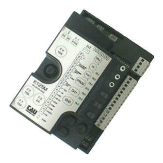
  • Page 32: Caractéristiques Techniques

    Dans le cas de longues distances (plus de 20 mètres) pour les commandes N.A et N.C. (exemple OUVRE/FERME, STOP, PIETON etc.) et pour éviter un mauvais fonctionnement du portail, nous conseillons d’utiliser un relais pour découpler les commandes (modèle relais TAU 750T-RELE). 2. ESSAI Une fois que la connexion a été...
  • Page 33 entrée PHOTOCELLULES ou DISPOSITIFS DE SÉCURITÉ actifs en fer- meture (contact Normalement Fermé) ; leur intervention, en phase de fermeture, provoque l’arrêt suivi de la réouverture totale du portail, en phase d’ouverture, elle provoque l’arrêt momentané du portail jusqu’à l’enlèvement de l’obstacle détecté (en cas de programmation, dip-switch n°3 ON).
  • Page 34: Procédure De Mémorisation

    5. PROCÉDURE DE MÉMORISATION ATTENTION : Après avoir alimenté la logique de commande, attendre 2 secondes avant de commencer les manœuvres de réglage. Le portail doit nécessairement avoir les butées de sécurité aussi bien en ouverture qu’en fermeture. Après avoir terminé l’installation de l’automatisme : 1_ mettre le portail à...
  • Page 35: Fonctionnement

    BARRE PALPEUSE DL7 (TENSION) led verte de signalisation PRÉSENCE ALIMENTATION (tension batterie aussi) 8. CARACTÉRISTIQUES DE LA K125M ED - DL3 La led, en plus d’indiquer la présence de tension, signale les éventuelles erreurs avec une série de clignotements prédéfinis : toujours allumée :...
  • Page 36: Carte Chargeur De Batterie (Intégrée)

    Pic d’absorption excessive du motoréducteur, contrôler l’absence d’obstacles le long de la course du portail, vérifier l’absorption de courant du moteur à vide et appliquée au portail. 5 clignotements : absence signal encodeur ; Contrôler le câblage, vérifier l’encodeur à l’aide du TEST-ENCODEUR (en option), vérifier que le moteur tourne librement si alimenté...
  • Page 37: Fonctions Avançées

    • si la remise a lieu après une intervention manuelle (centrale de commande toujours alimentée), il faudra 4 ou 5 cycles complets pour réaligner le portail. Pendant ces cycles le ralentissement nor- mal ainsi que les butées ne seront pas observés. 10.
  • Page 38: Effacement Émetteurs

    Intervertir les connexions du moteur sur le bornier (bornes 20 et 21). 13. GARANTIE: CONDITIONS GÉNÉRALES La garantie TAU a une durée de 24 mois à compter de la date d’achat des produits (le document fiscal de vente, ticket de caisse ou facture).
  • Page 39 DECLARACIÓN DE INCORPORACIÓN DEL FABRICANTE (de acuerdo con la Directiva Europea 2006/42/CE Adj. II.B) Fabricante: TAU S.r.l. Dirección: Via E. Fermi, 43 36066 Sandrigo (Vi) ITALY Declara bajo su propia responsabilidad que el producto: Central electrónica de control fabricado para el movimiento automático de:...
  • Page 40: Advertencias Importantes

    Este manual está destinado sólo al personal técnico cualificado para la instalación. Ninguna información contenida en este manual puede ser considerada interesante para el usuario final. Este manual acompaña a la central K125M; por lo tanto, ¡no debe utilizarse para otro tipo de producto! Advertencias importantes: Corte la alimentación de red a la tarjeta antes de acceder a ella.
  • Page 41: Características Técnicas

    1. TARJETA DE MANDO PARA MOTORREDUCTOR T-ONE5B • LÓGICA CON MICROPROCESADOR • ESTADO DE LAS ENTRADAS VISUALIZADO POR LEDs • PROTECCIÓN ENTRADA LÍNEA CON FUSIBLE • FUNCIÓN “ENTRADA PEATONAL” • CIRCUITO DE DESTELLO INCORPORADO • RADIORRECEPTOR DE 433,92 MHz INTEGRADO DE 2 CANALES (CH) •...
  • Page 42 entrada alimentación tarjeta 13,5 Vac - Alimentado por el transforma- FS1 - FS2 ALIMENTACIÓN dor toroidal colocado en el correspondiente compartimiento del motor T-ONE5B y protegido por un fusible (F 6,3A) en la alimentación 230 Vac. entrada BANDA SENSIBLE (Banda sensible resistiva o borde fijo); Funciona sólo du- rante la etapa de apertura de la cancela y provoca la parada momentánea de la cancela y su cierre parcial por alrededor de 20 cm así...
  • Page 43: Procedimiento De Memorización

    salida 2° CANAL RADIO (su funcionamiento depende de los dip-switch nros. 7 - 8) se debe utilizar para abrir/cerrar otra cancela o para accionar 2° CANAL 16 - 17 las luces del jardín, o para la función “ILUMINACIÓN DE ZONA”. RADIO Atención: utilizar un relé...
  • Page 44: Led De Diagnóstico

    BORDE SENSIBLE DL7 (TENSION) led verde de aviso PRESENCIA TENSIÓN (también tensión batería) 8. CARACTERÍSTICAS DE LA K125M LED - DL3 El led, además de indicar la presencia de la alimentación, señala eventuales errores con una serie de destellos predefinidos:...
  • Page 45 siempre encendido: funcionamiento regular; 1 destello: tensión de la batería tampón inferior a 11,3 Vdc; Controle la alimentación de red, cargue la batería, sustituya la batería; 2 destellos: error fototest; Desactive el fototest (dip-switch 6 en OFF), verifique el funcionamiento de las fotocélulas y su conexión; 3 destellos: falta tensión de red;...
  • Page 46: Funciones Avanzadas

    9. PROCEDIMIENTO DE ALINEACIÓN DE LA PUERTA Si fuera necesario operar manualmente la puerta, utilice el desbloqueo manual. Para volver al funcio- namiento automático: • después de un apagón (el cuadro de maniobras queda sin alimentación durante cierto tiempo), el ac- cionador entrará...
  • Page 47 Invierta entre ellas las conexiones del motor en el terminal de conexiones (bornes 20 y 21). 13. GARANTÍA: CONDICIONES GENERALES La garantía de TAU tiene una cobertura de 24 meses a partir de la fecha de compra de los productos (la fecha válida es la que figura en el comprobante de venta, recibo o factura).
  • Page 48 Via Enrico Fermi, 43 - 36066 Sandrigo (VI) - Italy Tel +39 0444 750190 - Fax +39 0444 750376 info@tauitalia.com - www.tauitalia.com Foglietto illustrativo CARTA - Raccolta differenziata. Segui le indicazioni del tuo comune. (N.B.: togliere i punti metallici) Instruction leaflet PAPER - Waste separation.

Table des Matières