Publicité

Les langues disponibles
  • FR

Les langues disponibles

  • FRANÇAIS, page 41

Liens rapides

GUIDA ALL'INSTALLAZIONE
INSTALLATION GUIDE
INSTALLATIONSANLEITUNG
NOTICE D'INSTALLATION
GUÍA PARA LA INSTALACIÓN
GUIA DE INSTALAÇÃO
D749MA
IT - Istruzioni originali

Publicité

Table des Matières
loading

Sommaire des Matières pour tau D749MA

  • Page 1 GUIDA ALL’INSTALLAZIONE INSTALLATION GUIDE INSTALLATIONSANLEITUNG NOTICE D’INSTALLATION GUÍA PARA LA INSTALACIÓN GUIA DE INSTALAÇÃO D749MA IT - Istruzioni originali...
  • Page 2 SCHEMA D749MA SCHALTPLAN SCHÉMA ESQUEMA DEL ESQUEMA CABLAGGIO WIRING DER D749MA CÂBLAGE CABLEADO DE LIGAÇÕES D749MA DIAGRAM D749MA D749MA D749MA Dip-switches 9 10 11 12 Trimmer: 9 10 11 12 D749MA LEDs: FIXED SAFETY EDGE PROG EXT. PHOTO INT. PHOTO...
  • Page 3: Power Supply

    - Morsetti 1 - 2: Attenzione a NON invertire la polarità. - Se il jumper 6 non è inserito, verrà attivata la modalità basso consumo e le uscite 11-12, 12-13, 14-15, 16-17 e 16-18 verranno spente. - Terminals 1 – 2: Careful NOT to invert polarity. - If the jumper J6 is not plugged in, at the end of each maneuver output 11 and 12 will be switched off (energy saving mode).
  • Page 4 COME FISSARE LA HOW TO FIX THE WIE MAN DAS D749MA CENTRALE D749MA D749MA CONTROL STEUERGERÄT AN DER SULLA SCATOLA UNIT ON THE BOX BOX BEFESTIGT PORTAFUSIBILI...
  • Page 5 COMMENT FIXER CÓMO FIJAR LA UNIDAD COMO FIXAR A UNIDADE L’UNITÉ DE CONTRLE DE CONTROL D749MA A DE CONTROLE D749MA D749MA À LA BOÎTE LA CAJA NA CAIXA Portafusibili Fuse holder Sicherungshalter Porte-fusible Portafusibles Fusível Trasformatore Transformer TRASFORMATORE Transformator Transformateur...
  • Page 6: Avvertenze Importanti

    Il presente manuale è destinato solamente al personale tecnico qualificato per l’installazione. Nessuna informazione contenuta nel presente fascicolo può essere considerata d’interesse per l’utilizzatore finale. Questo manuale è allegato alla centralina D749MA; non deve pertanto essere utilizzato per prodotti diversi! Avvertenze importanti: Togliere l’alimentazione di rete alla scheda prima di accedervi.
  • Page 7 PEDONALE, ecc), al fine di evitare malfunzionamenti del cancello si renderà necessario disac- coppiare i vari comandi mediante RELAYS oppure utilizzando il nostro dispositivo 750T-RELE. 2. INTRODUZIONE La scheda D749MA può funzionare in due modalità differenti, selezionabili tramite il ponticello J6 (vedi schema cablaggio). J6 Ponticellato: modalità...
  • Page 8 (vedi nota alla fine del paragrafo). ATTENZIONE: l’uscita di default è monostabile attiva 2 sec. Per com- mutarla in bistabile attiva oppure per modificare il tempo di attiva- zione è necessario operare tramite programmatore palmare TAU- PROG (vedi istruzioni relative).
  • Page 9 ingresso antenna radioricevente ad innesto solo per ricevitori 433,92 21 - 22 ANTENNA MHz. (21= MASSA - 22= SEGNALE) uscita alimentazione motore (M2) 18V DC 23 - 24 MOTORE (M2) (23= POSITIVO - 24= NEGATIVO) usare cavi 2,5 mm alimentazione e ingresso encoder (25= BIANCO segnale - 26= BLU nega- 25 - 26 - 27 ENCODER (M2) tivo - 27= MARRONE positivo) uscita alimentazione motore (M1) 18V DC...
  • Page 10: Procedura Di Memorizzazione

    in seguito all’intervento del contatto fotocellula (ingresso 7 - 9), l’auto- RICHIUDE mazione si chiude automaticamente dopo 5 secondi. DOPO FOTOCELLULA funzione disinserita. l’automazione ignora i comandi di chiusura durante l’apertura e il tempo di pausa. NO REVERSE l’automazione si comporta come stabilito dal dip switch nr. 2. la funzione prelampeggio è...
  • Page 11 Accertarsi pertanto di non sostare nelle vicinanze dell’automazione durante la procedura di memorizzazione. 7. CARATTERISTICHE DELLA D749MA APERTURA E CHIUSURA COMANDATA DA OROLOGIO É possibile comandare l’apertura e la chiusura dell’automazione mediante un orologio digitale che in uscita disponga di un contatto pulito N.A.
  • Page 12 batteria carica, tensione di rete presente; sempre acceso (Verde): batteria in carica; sempre acceso (Giallo): batteria carica, tensione di rete assente; 1 lampeggio ogni 4 sec (Verde): Controllare l’alimentazione di rete; alimentazione con pannello fotovoltaico (morsetti 1-2), ca- 1 lampeggio ogni 4 sec (Giallo): ricabatteria disattivato;...
  • Page 13 Picco di eccessivo assorbimento del motoriduttore, controllare l’assen- za di ostacoli lungo la corsa dell’automazione, verificare l’assorbimento di corrente del motore a vuoto e applicato alla chiusura; Intervento sicurezza bordo sensibile 7 lampeggi (Rosso): È necessario un impulso di comando per effettuare la chiusura; errore memoria Eeprom esterna;...
  • Page 14 10. RADIO RICEVITORE 433,92 MHz INTEGRATO Il radio ricevitore può apprendere fino ad un max di 30 codici rolling code (S-2RP, S-4RP, K-SLIM-RP, T-4RP) da impostare liberamente su tre canali. Il primo canale comanda direttamente la scheda di comando per l’apertura dell’automazione; il secondo canale comanda un relè...
  • Page 15 11. PREDISPOSIZIONE AL FUNZIONAMENTO CON LE APPLICAZIONI TAU Per poter utilizzare le applicazioni TauApp e TauOpen si renderà necessario collegare all’ingresso J4 della centrale D749MA mediante il cavo in dotazione i rispettivi dispositivi T-WIFI e T-CONNECT. Per attivare il funzionamento delle applicazioni vedere le rispettive istruzioni.
  • Page 16 24 per M2). 13. GARANZIA: CONDIZIONI GENERALI La garanzia della TAU ha durata di 24 mesi dalla data di acquisto dei prodotti (fa fede il documento fiscale di vendita, scontrino o fattura). La garanzia comprende la riparazione con sostituzione gratuita (franco sede TAU: spese di imballo e di trasporto sono a carico del cliente) delle parti che presentano difetti di lavorazione o vizi di materiale riconosciuti dalla TAU.
  • Page 17 Cancelli a Battente per uso in ambiente: Residenziale / Condominiale completo di: Radioricevente e scheda carica batteria Modello: D749MA Tipo:D749MA Numero di serie: vedi etichetta argentata Denominazione commerciale: Quadro di comando per uno/due motori 12V con encoder È...
  • Page 18 This manual is designed to assist qualified installation personnel only. It contains no information that may be of interest to final users. This manual is attached to the D749MA control unit, therefore it may not be used for different products! Important warnings: Disconnect the mains power supply to the board before accessing it.
  • Page 19: Technical Characteristics

    PEDESTRIAN, etc.), in order to avoid gate malfunctions, it will be necessary to uncouple the various controls using RELAYS or using our 750T-RELE device. 2. INTRODUCTION The D749MA board has two working modes, selectable through the J6 jumper (see wiring diagram). J6 Jumped: standard mode, i.e. the control unit is powered all the time;...
  • Page 20 PHOTOCELL OR SAFETY DEVICE input INSIDE the automation (Normally Closed contact). When these devices trigger during the opening phase, they INTERNAL 7 - 8 temporarily stop the automation until the obstacle has been removed; PHOTOCELLS during the closing phase they stop the automation and then totally open it again.
  • Page 21: Important

    Quick coupling for the connection of the T-WIFI and T-CONNECT devices * The outlets can be configured using the TAUPROG or TAUAPP (T-WIFI) (see relative instructions). The standard configuration is shown in the table. If Jumper J6 is not plugged in, energy saving mode will be activated and, at the end of each manouvre, outputs 11-12, 12-13, 14-15, 16-17 and 16-18 will be switched off.
  • Page 22 enables just one motor (M1). MOTORS SELECTION enables 2 motors. 9-10-11 Automation type selection Dip 9 Dip 10 Dip 11 Automation ARM, ZIP12 up to 200 Kg or leaf less than 3 m.; ARM, ZIP12 over 200 kg and leaf less than 3 m R18BENC BIUNO-BT ARM, ZIP12 with leaf above 3 m and 400 Kg max...
  • Page 23 7. D749MA CHARACTERISTICS TIMER-OPERATED OPENING AND CLOSING CYCLES The opening/closing of the automation can be controlled by means of a timer that has a free N.O. output contact (relay). The timer must be connected to terminals 4 - 6 (OPEN/CLOSE button) and can be programmed so that, at the desired opening time, the relay contact closes until the desired closing time (when the timer’s relay contact opens, enabling the automatic closing of the gate).
  • Page 24 saving in progress; fast flashing (yellow): phototest error 1 flash (red): Disable phototest (dip-switch 6 OFF), check the operation of the photocells and their connection; unknown status, next operation REALIGNMENT; 1 flash (yellow): obstacle for motor 1; 2 flashes (red): Make sure there are no obstacles across the path of the automation and that it slides smoothly;...
  • Page 25 channel CH3 waiting to be saved; always on (red): CH3 channel memory full; fast flashing (red): CH1 channel waiting to be cancelled; flashing (green): cancelling of channel CH1 in progress; always on (green): CH2 channel waiting to be cancelled; flashing (yellow): cancelling of channel CH2 in progress;...
  • Page 26 7_ to program transmitters into the third channel, repeat procedure from point 1 using CH1 and CH2 buttons at the same time (DL8 will turn on red); 8_ to exit the learning mode without memorising a code, press button CH1 or CH2 briefly. If the maximum number of radio controls is reached (30), the LED DL8 will begin to flash rapidly for about 3 seconds but without performing memorisation.
  • Page 27 11. SET-UP FOR OPERATION WITH TAU APPS In order to use the TauApp and TauOpen apps, it will be necessary to connect to input J4 of the D749MA control unit using the supplied cable, the respective T-WIFI and T-CONNECT devices. To activate the operation of the apps see the respective instructions.
  • Page 28 Residential / Communities complete with: Radioreceiver and battery charger board Model: D749MA Type:D749MA Serial number: see silver label Commercial name: Control panel for one-two 12V motors with encoder Has been produced for incorporation on an access point (swing gate) of for assembly with other devices used to move such an access point, to constitute a machine in accordance with the Machinery Directive 2006/42/CE.
  • Page 29: Wichtige Hinweise

    Das vorliegende Handbuch ist nur für technisches, zur Installation qualifiziertes Personal bestimmt. Die im vorliegenden Heft enthaltenen Informationen sind für den Endbenutzer nicht interessant. Diese An- leitung liegt der Steuerung D749MA bei und darf daher nicht für andere Produkte verwendet werden! Wichtige Hinweise: Vor Eingriffen an der Steuerkarte die Netzstromversorgung abtrennen.
  • Page 30: Technische Merkmale

    FUSSGÄNGER usw.) ist es zur Vermeidung von mangelhaften Funktionen notwendig, die verschiede- nen Steuerungen über die RELAIS zu trennen oder unsere Vorrichtung 750T RELE zu nutzen. 2. EINFÜHRUNG Die Karte D749MA kann mit zwei verschiedenen Betriebsweisen arbeiten, wählbar mit dem Jumper J6 (siehe Verkabelungsplan). J6 Gebrückt: Modalität Standard, das heißt, das Steuergerät ist immer gespeist;...
  • Page 31 NC-Eingang, Taste STOPP – hält die Automatisierung unabhängig von 5 - 6 STOP seiner Position an; stellt die automatische Schließung vorübergehend ab, falls programmiert. (5= STOP - 6= GEM.) Eingang für FOTOZELLEN oder SICHERHEITSVORRICHTUNGEN AUF DER INNENSEITE der Automatisierung (normal geschlossener Kon- takt).
  • Page 32 Ausgang 2. Funkkanal – zum Steuern einer anderen Automatisierung oder zum Einschalten von Lichtern usw..(potentialfreier NO-Kontakt). Achtung: für die Lichtsteuerung (oder andere Belastungen) mit dem 2. Kanal des Funkempfängers entsprechend stärkere Hilfsrelais unbedingt verwenden (siehe Hinweis am Ende des Absatzes). 19 - 20* 2.
  • Page 33 Dip-Switch nach beendeter Öffnung ist die Schließung der Automatisierung nach AUTOMATISCHE Ablauf einer an Trimmer T.C.A. eingestellten Zeit automatisch. SCHLIEßUNG für das Schließen ist ein manueller Steuerbefehl erforderlich. bei funktionierender Automatisierung, verursacht eine Auf/Zu Befeh- lesequenz eine ÖFFNUNG-SCHLIEßUNG-ÖFFNUNG-SCHLIEßUNG usw. der Automatisierung. 2 / 4 TAKT unter denselben Bedingungen verursacht die gleiche Befehlesequenz eine ÖFFNUNG-STOPP-SCHLIEßUNG-STOPP-ÖFFNUNG-STOPP usw.
  • Page 34 Halten Sie sich daher während des Abspeicherungsverfahrens nicht in der Nähe der Automatisierung auf. 7. MERKMALE DER SCHALT- UND STEUERTAFEL D749MA ÖFFNUNG UND SCHLIEßUNG MIT ZEITUHR Die Öffnung und Schließung der Automatisierung kann über eine digitale Uhr gesteuert werden, die im Ausgang über einen potentialfreien NO-Kontakt (Relais) verfügt.
  • Page 35 8. DIAGNOSE-LEDs DL1 - Rote LED für Taste GEHFLÜGEL DL2 - Rote LED für Taste ÖFFNET/SCHLIEßT DL3 - Grüne LED für Taste STOPP DL4 - Grüne LED für INNEN FOTOZELLEN DL5 - Grüne LED für AUSSEN FOTOZELLEN DL6 - Grüne LED für SICHERHEITSLEISTE LED - DL7 Die LED DL7 zeigt das Vorhandensein der Batterie sowie außerdem eventuelle Fehler durch Aufblinken...
  • Page 36 Kein Signal Encoder Motor 1; 3 Aufblinken (rot): Kontrollieren Sie die verkabelung, überprüfen Sie den Encoder mit TEST- ENCODER (Option); Kein Signal Encoder Motor 2; 3 Aufblinken (gelb): Kontrollieren Sie die verkabelung, überprüfen Sie den Encoder mit TEST- ENCODER (Option); Kein Signal Encoder Motor 1; 4 Aufblinken (rot): Kontrollieren Sie die Verkabelung, stellen Sie sicher, dass sich der Motor ungehindert dreht, wenn er direkt von der Batterie gespeist wird, über-...
  • Page 37 Warten vollständiges Löschen der Funkkanäle; Aufblinken (gelb + gelb): Die Anzeige mehrerer Fehler erfolgt mit einer Pause von 2 Sekunden zwischen einer Anzeige und der nächsten. Wird eine Person/Hindernis während der Schließbewegung erkannt, so öffnet die Schranke langsam komplett. Automatischer Zulauf wird deaktiviert bis auf weiteren Befehl. im Falle von fünf Auslösungen während derselben Schließbewegung, erhöht die Steuerungsplatine die Zeit des automatischen Zulaufs.
  • Page 38 FERNPROGRAMMIERUNG MITTELS T-4RP / K-SLIM-RP / S-2RP / S-4RP (V 4.X) Mit der neuen Version von Software V 4.X ist es möglich, die Fernselbstlernung der neuen Version von Handsendern T-4RP / K-SLIM-RP / S-2RP / S-4RP (V 4.X) auszuführen, d.h. ohne der Programmierungs- tasten des Empfängers zu drücken.
  • Page 39: Garantie: Allgemeine Bedingugen

    M1; Klemmen 23 und 24 durch die M2). 13. GARANTIE: ALLGEMEINE BEDINGUGEN Die Garantie der Firma TAU hat 24 Monate Gültigkeit ab Kaufdatum (das Datum muss durch eine Quit- tung oder Rechnung belegt sein). Die Garantie schließt die Reparatur mit kostenlosem Ersatz (ab Werk der Firma TAU: Verpackungs- und Transportkosten gehen zu Lasten des Kunden) jener Teile ein, die von TAU anerkannte Fabrikations- oder Materialfehler aufweisen.
  • Page 40 Declares under its sole responsibility, that the product: Electronic control unit designed for automatic movement of: Swing Gates for use in a: Residential / Communities complete with: Radioreceiver and battery charger board Model: D749MA Type:D749MA Serial number: see silver label Commercial name: Control panel for one-two 12V motors with encoder Has been produced for incorporation on an access point (swing gate) of for assembly with other devices used to move such an access point, to constitute a machine in accordance with the Machinery Directive 2006/42/CE.
  • Page 41: Recommendations Générales

    Le présent manuel est destiné exclusivement au personnel technique qualifié pour l’installation. Aucune information contenue dans ce fascicule ne peut être considérée comme intéressante pour l’utilisateur final. Ce manuel est joint à la logique de commande D749MA, il ne doit donc pas être utilisé pour des produits différents ! Recommandations importantes : Couper l’alimentation électrique de la carte avant d’y accéder.
  • Page 42: Caractéristiques Techniques

    OUVRE/FERME, STOP, PIETON etc.) et pour éviter un mauvais fonctionnement du portail, nous conseillons d’utiliser un relais pour découpler les commandes (modèle relais TAU 750T-RELE). 2. INTRODUCTION La fiche D749MA peut fonctionner en deux modalités différents, sélectionnables par pontet J6 (voir schéma de câblage). J6 pontés: modalité...
  • Page 43 entrée N.O. touche PIÉTON - Commande l’ouverture et la fermeure totale 3 - 6 PIÉTON di moteur 1 (M1) et est réglée dans le fonctionnement par les dip-switchs 2 et 4. (3= PIET. - 6= COM) entrée N.O. touche OUVRE/FERME – Commande l’ouverture et la fermeture 4 - 6 OUVRE/FERME de l’automatisme et est réglée dans le fonctionnement par les dip-switchs...
  • Page 44: Important

    ATTENTION : la sortie par défaut est monostable active 2 sec. Pour la commuter en bistable active ou bien pour modifier le temps d’activa- tion il est nécessaire d’actionner avec le programmateur de poche TAU- PROG (voir instructions relatives). entrée antenne radioréceptrice embrochable seulement pour récepteurs...
  • Page 45: Procédure De Mémorisation

    “RÉGLAGES DE FABRIQUE“ (voir page 46). BARRE PALPEUSE RESISTIF (étau n ° 10). BARRE PALPEUSE BARRE PALPEUSE CONTACT N.C. ( étau n ° 10). Remarque: s’il n’est pas utilisé, maintenir le dip sur OFF. 6. PROCÉDURE DE MÉMORISATION ATTENTION : Après avoir alimenté...
  • Page 46 Par conséquent, assu- rez-vous de ne pas rester au prés de l’automatisme pendant la procédure de stockage. 7. CARACTÉRISTIQUES DE LA D749MA OUVERTURE ET FERMETURE COMMANDÉE PAR UNE HORLOGE Il est possible de commander l’ouverture et la fermeture de l’automatisme avec une horloge numé- rique disposant en sortie d’un contact N.O.
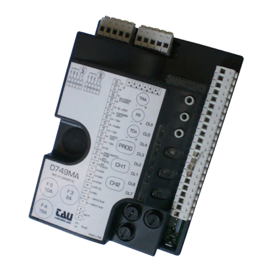
  • Page 47 8. LEDS DE DIAGNOSTICS DL1 - Rouge led de signalisation touche PIÉTON DL2 - Rouge led de signalisation touche OUVRE/FERME DL3 - Verte led de signalisation touche STOP DL4 - Verte led de signalisation PHOTOCELLULES INTERNES DL5 - Verte led de signalisation PHOTOCELLULES EXTERNES DL6 - Verte led de signalisation BARRE PALPEUSE LED - DL7...
  • Page 48 présence obstacle pour le moteur 2 2 clignotement (jaune): Contrôler l’absence d’obstacles le long de la course de l’automatisme et son coulissement fluide. Dans le cas d’une intervention obstacle avec la fonction de fermeture au- tomatique habilitée, la manœuvre automatique de fermeture du portail sera désactivée.
  • Page 49: Remise Fonctionnement Automatique

    Les led DL7 DL8 quand ils clignotent simultanément, ont la fonction de signaler: procédure de réinitialisation de fabrique à confirmer; clignotement (rouge + rouge): en attente effacement total des chaînes de radio; clignotement (jaune + jaune): L’indication de plusieurs erreurs est effectuée avec une pause de 2 secondes entre une signalisation et la suivante.
  • Page 50 Avec la nouvelle version de logiciel V 4.X il est possibile d’effectuer l’apprentissage reculé de la dernière version des émetteurs T-4RP / K-SLIM-RP / S-2RP / S-4RP (V 4.X), c’est-à-dire sans appuyer sur les pous- soires de programmation du récepteur. Il faudra seulement utiliser un émetteur déjà...
  • Page 51: Mise En Etat De Marche Avec Les Application

    24 pour le moteur 2). 13. GARANTIE: CONDITIONS GÉNÉRALES La garantie TAU a une durée de 24 mois à compter de la date d’achat des produits (le document fiscal de vente, ticket de caisse ou facture). La garantie comprend la réparation avec remplacement gratuit (départ usine TAU: frais d’emballage et de transport à...
  • Page 52 : Portails à Battant pour l’utilisation en milieu : Résidentiel / Intensif muni de : Récepteur et carte chargeur de batterie Modèle : D749MA Type :D749MA Numéro de série : voir étiquette argentée Appellation commerciale : Logique de commande pour un ou deux moteurs 12V avec encodeur est réalisé...
  • Page 53 Durante el diseño de sus equipos, TAU respeta las normativas aplicables al producto (véase la declaración de conformidad adjunta); también es fundamental que el instalador, al realizar la instalación, respete escrupulo- samente las normas.
  • Page 54: Características Técnicas

    CIERRA, STOP, PEATONAL, etc.), para evitar un mal funcionamiento de la puerta será necesario desacoplar los diferentes mandos con RELÉS o utilizando nuestro dispositivo 750T-RELE. 2. INTRODUCCIÓN La tarjeta D749MA puede funcionar en dos modos diferentes que se seleccionan con el puente J6 (véase el diagrama de cableado). J6 Puenteado: modalidad estándar, es decir la central siempre está...
  • Page 55 entrada N.C. botón STOP – Detiene el automatismo dondequiera que se 5 - 6 STOP encuentre, inhibiendo momentáneamente el cierre automático, de haber sido programado. (5= STOP - 6= COM) entrada FOTOCÉLULAS O DISPOSITIVOS DE SEGURIDAD SITUADOS AL INTERNO respecto de l’automatismo ( contacto Normalmente Cerrado). FOTOCÊLULAS Su accionamiento, durante la apertura, provoca el paro momentáneo 7 - 8...
  • Page 56 alimentación y entrada codificador. (25= BLANCO señal - 26= AZUL nega- 25 - 26 - 27 ENCODER (M2) tivo - 27= MARRÓN positivo) salida alimentación motor M1 18V DC (28= POSITIVO - 29= NEGATIVO) 28 - 29 MOTOR (M1) utilizar cables de 2.5 mm alimentación y entrada codificador.
  • Page 57: Procedimiento De Memorización

    la función “verificación de las fotocélulas” está activada. FOTOTEST la función “verificación de las fotocélulas” está desactivada. Nota: dejar en OFF cuando no se usan las fotocélulas. la función “golpe a la apertura” está activada. Permite desenganchar la cerradura GOLPE A LA eléctrica (se puede utilizar sólo si se dispone de cerradura eléctrica);...
  • Page 58: Led De Diagnóstico

    Por lo tanto, asegúrese de no estar cerca del automatismo durante el proceso de memo- rización. 7. CARACTERÍSTICAS DE LA D749MA APERTURA Y CIERRE CONTROLADA A TRAVÉS DEL RELOJ Es posible accionar la apertura y el cierre del automatismo con un reloj digital que disponga en la salida de un contacto sin tensión N.A.
  • Page 59 batería averiada; destello rápido (Rojo): Sustituya la batería; LED - DL8 El LED DL8 señala los avisos/errores de la lógica de la tarjeta con una serie de destellos predetermina- dos de diferentes colores: Leyenda: led siempre encendido; led intermitente; funcionamiento regular; 1 destello (Verde) cada 4 s: destello alternado:...
  • Page 60 error memoria Eeprom externa; 8 destellos (Rojo): Sustituya el módulo de memoria externa; error datos en Eeprom (interna/externa); 8 destellos (Amarillo): Realice el proceso de RESET DE LA MEMORIA RADIO; Además de los avisos/errores de la parte lógica, el LED DL8 también indica el estado de la central du- rante la memorización de los emisores.
  • Page 61 1 A) y el tercero canal controla directamente el cuadro para la apertura peatonal. APRENDIZAJE DE LOS RADIOCONTROLES CH1 = 1° canal (ABRE/CIERRA) CH2 = 2° canal CH3 = 3° canal (PEATONAL) 1_ Pulse brevemente la tecla CH1 si quiere asociar un radiocontrol a la función ABRE/CIERRA; 2_ cuando el LED DL8 (verde) se enciende con luz fija, indica el modo de aprendizaje de los códigos (si no se introduce ningún código antes de 10 segundos, la tarjeta sale del modo de programación);...
  • Page 62 1; bornes 23 y 24 por el motor 13. GARANTÍA: CONDICIONES GENERALES a garantía de TAU tiene una cobertura de 24 meses a partir de la fecha de compra de los productos (la fecha válida es la que figura en el comprobante de venta, recibo o factura).
  • Page 63 • Si no se han utilizado todos los componentes originales TAU para la instalación del automatismo. • Si los daños han sido causados por catástrofes naturales, modificaciones, sobrecargas de tensión, alimentación incorrecta, reparaciones inadecuadas, instalación incorrecta u otras causas no imputa-...
  • Page 64: Informação Importante

    Este producto pode unicamente ser instalado e mantido por pessoal qualificado em conformidade com as actuais leis, normas e directivas. Ao conceber os seus produtos a TAU cumpre todos as normas aplicáveis ( por favor consulte a declaração de conformidade anexa). É de suprema importância que os instaladores observem escrupulosamente as mesmas normas quando instalam o producto.
  • Page 65 RELAYS ou utilizando o nosso dispositivo 750T-RELE. 2. INTRODUÇÃO A placa D749MA possui dois modos de operar, seleccionável através do jumper J6 (ver esquema eléctrico). J6 Ligado modo padrão, i.e. a unidade de controlo está sempre alimentada;...
  • Page 66 Botão DE ABERTURA / FECHO N.A. – Controla a abertura e fecho da 4 - 6 ABERTURA / FECHO automação e é controlado através das funções dos dip-switch 2 e 4. (4= ABERTURA / FECHO - 6= COMUM). Entrada botão STOP N.F. – para a automação em qualquer posição, 5 - 6 STOP temporariamente impedindo o fecho automático, se programado...
  • Page 67 Entrada de antena sómente para receptores 433,92 MHz. 21 - 22 ANTENA (21= MASSA - 22= SINAL). Saída alimentação motor 18V DC (23= POSITIVO – 24= NEGATIVO) 23 - 24 MOTOR (M2) use cabos de 2,5 mm Conector rápido para a ligação do ENCODER. (25 = BRANCO sinal - 26= 25 - 26 - 27 ENCODER (M2) AZUL negativo - 27= CASTANHO positivo).
  • Page 68 Após as fotocélulas serem actuadas (entrada 7 – 9), a automação fecha FECHAR DE NOVO automaticamente após 5 segundos. APÓS FOTOCÉLULAS Função inactiva. A automação ignora os comandos de fecho durante a abertura e o tempo de pausa. NO REVERSE A automação responde conforme definido no dip-switch nº...
  • Page 69: Led' S De Diagnóstico

    Certifique-se que não está próximo da automação durante a memorização. 7. CARACTERÍSTICAS DA D749MA ABERTURA E FECHO CONTROLADOS ATRAVÉS DE TEMPORIZADOR É possível controlar a abertura e o fecho do automatismo com um relógio digital que possua um con- tacto N.A.
  • Page 70 1 piscar a cada 2 segundos: carga bateria baixa; (vermelho) Carregue a bateria, substitua a bateria; bateria defeituosa; piscar rápido (vermelho): Substitua a bateria; LED - DL8 O LED DL8 indica erros na placa electrónica com uma série de pré-lampejos em difrentes côres: Indicação: led sempre aceso;...
  • Page 71 Picos de absorção excessivos do motorredutor, verifique que não existem obstáculos no caminho da automação, ve- rifique a corrente absorvida pelo motor numa condição de sem carga e quando aplicada à portão. fecho automático desactivado após 5 tentativas conse- 6 piscar (vermelho): cutivas falhadas;...
  • Page 72 10. RECEPTOR RÁDIO INCORPORADO 433,92 MHz O receptor de rádio pode aprender até um máximo de 30 códigos de código contínuos (S-2RP, S-4RP, K-SLIM-RP, T-4RP) para ser definido livremente em três canais. O primeiro canal comanda directamente a placa electrónica de controlo para a abertura da automati- zação;...
  • Page 73 11. PREPARAÇÃO PARA OPERAÇÃO COM APLICAÇÕES TAU Para usar as aplicações TauApp e TauOpen, será necessário conectar à entrada J4 no painel de controle do D749MA os respectivos dispositivos T-WIFI e T-CONNECT usando o cabo fornecido. Para ativar o funcionamento das aplicações consulte as respectivas instruções.
  • Page 74 13. GARANTIA: CONDIÇÕES GERAIS A garantia TAU tem uma duração de 24 meses a contar da data de compra dos produtos (o documento fiscal de venda, recibo ou factura). Esta garantia cobre a reparação ou substituição a espensas TAU (à saída da fábrica: embalagem e trans- porte por conta do cliente) das peças que que apresentem defeitos de fabrico ou material defeituoso...
  • Page 75: Réinitialisation

    ITALIANO - VIDEO TUTORIAL - Come memorizzare un ra- - Come effettuare l' HARD - Come effettuare un HARD diocomando Rolling Code su RESET sulla centrale RESET della RADIORICEVENTE centrali Diamond. cancello automatico ENGLISH - VIDEO TUTORIAL - How to learn a Rolling Code HARD RESET - How to HARD RESET the...
  • Page 77 Via Enrico Fermi, 43 - 36066 Sandrigo (VI) - Italy Tel +39 0444 750190 - Fax +39 0444 750376 info@tauitalia.com - www.tauitalia.com Foglietto illustrativo CARTA - Raccolta differenziata. Segui le indicazioni del tuo comune. (N.B.: togliere i punti metallici) Instruction leaflet PAPER - Waste separation.

Table des Matières