Publicité

Les langues disponibles
  • FR

Les langues disponibles

  • FRANÇAIS, page 30

Liens rapides

GUIDA ALL'INSTALLAZIONE
INSTALLATION GUIDE
INSTALLATIONSANLEITUNG
NOTICE D'INSTALLATION
GUÍA PARA LA INSTALACIÓN
GUIA DE INSTALAÇÃO
DC20
DC20
opening
closing
opening
closing
slowdown
slowdown
auto close
speed
speed
torque
torque
open
close
delay
TM1
TM2
TM3
TM4
TM5
TM6
TM7
IT - Istruzioni originali

Publicité

Table des Matières
loading

Sommaire des Matières pour tau DC20

  • Page 1 GUIDA ALL’INSTALLAZIONE INSTALLATION GUIDE INSTALLATIONSANLEITUNG NOTICE D’INSTALLATION GUÍA PARA LA INSTALACIÓN GUIA DE INSTALAÇÃO DC20 DC20 opening closing opening closing slowdown slowdown auto close speed speed torque torque open close delay IT - Istruzioni originali...
  • Page 2 WIRING DIAGRAM DC20 SCHEMA CABLAGGIO DC20 SCHÉMA CÂBLAGE DC20 AVEC WITH PHOTOCELLS CON FOTOCELLULE CELLULES PHOTOÉLECTRIQUES (Grey sleeve) (Black sleeve) PAIR (Grey sleeve) (Black sleeve) PAIR Encoder power supply 12 Vdc LED-13 LED-12 LED-11 LED-10 LED-9 LED-8 LED-7 LED-6 LED-5...
  • Page 3 ESQUEMA ELÉCTRICO DC20 ESQUEMA CABLEADO DC20 VERDRAHTUNGSPLAN COM FOTOCÉLULAS CON FOTOCÉLULAS DC20 MIT FOTOZELLEN Senza selettore ponticellare il 25 con il 27 per selezionare “2 sensi” Without jumper selector the 25, with the 27 to select “2 directions” Sans sélecteur raccorder le 25 avec le 27 pour sélectionner "2 sens"...
  • Page 4 SCHEMA CABLAGGIO WIRING DIAGRAM SCHÉMA CÂBLAGE DC20 DC20 CON RILEVATORI DC20 WITH PRESENCE AVEC DÉTECTEUR DE DI PRESENZA DETECTORS PRÉSENCE INSIDE SENSOR S-10DOORRAD2 TEST POWER OUTSIDE SENSOR S-10DOORRAD2 TEST POWER Encoder power supply 12 Vdc LED-13 LED-12 LED-11 LED-10 LED-9 LED-8 LED-7 LED-6 LED-5...
  • Page 5 VERDRAHTUNGSPLAN ESQUEMA ELÉCTRICO ESQUEMA CABLEADO DC20 MIT DC20 COM DETECTORES DC20 CON DETECTORES NWESENHEITSDETEKTOR DE PRESENçA DE PRESENCIA F 5 - 3,15 A IN 230Vac Encoder power IN 230Vac supply 5 Vdc DC20 IN 32Vac DL 1 F2 - 6,3 A...
  • Page 6: Avvertenze Importanti

    Il presente manuale è destinato solamente al personale tecnico qualificato per l’installazione. Nessuna informazione contenuta nel presente fascicolo può essere considerata d’interesse per l’utilizzatore finale. Questo manuale è allegato alla centralina DC20; non deve pertanto essere utilizzato per prodotti diversi! Avvertenze importanti: Togliere l’alimentazione di rete alla scheda prima di accedervi.
  • Page 7: Caratteristiche Tecniche

    ruzioni sulla linea e falsi contatti; non riutilizzare vecchi cavi preesistenti; COLLAUDO A collegamento ultimato: • I Leds verdi (DL7-8-9-11-12-13) devono essere tutti accesi (corrispondono ciascuno ad un ingresso Normalmente Chiuso). Si spengono solo quando sono interessati i comandi ai quali sono asso- ciati.
  • Page 8: Collegamenti Alla Morsettiera

    - collegamento TLINETD. Morsetti Ingresso/Uscita Descrizione NEGATIVO ALIMENTAZIONE T-LINETD - 5 V DC B SEGNALE T-LINETD segnale comunicazione T-LINETD con DC20 A SEGNALE T-LINETD segnale comunicazione T-LINETD con DC20 POSITIVO ALIMENTAZIONE T-LINETD + 5 V DC CONNETTORE J3 - connettore opzionale.
  • Page 9 Chiusa Nessuna. In apertura Nessuna. FOTOCELLULA In chiusura Inverte il movimento ed apre. 15 - 16 (Contatto N.C.) La porta non chiude finchè le fotocellule rimangono Aperta impegnate. In pausa Nessuna. TEST RILEVATORI DI 17= + TEST 17 - 18 PRESENZA 18= - TEST Connettore J16:...
  • Page 10 La porta non apre finchè l’ingresso rimane impe- Chiusa gnato. In apertura Arresta l’automazione. In chiusura Arresta l’automazione. STOP/ANTIPANICO 24 - 21 La porta non chiude finchè l’ingresso rimane im- (Opz.) (NC) Aperta pegnato. (21= Comune) La porta non apre finchè l’ingresso rimane impegna- In pausa to.
  • Page 11 USCITA INTERBLOCCO CONTATTO INTERBLOCCO COMUNE COMUNE CONTATTO INETRBLOCCO CONNETTORE J11 - connettore per scheda caricabatteria. CONNETTORE J12 - non utilizzato. CONNETTORE J13 - connettore batteria. CONNETTORE J14 - connettore per primario del trasformatore. CONNETTORE J15 - collegamento ingesso alimentazione 230V 50hz. CONNETTORE J6 - connettore per secondario del trasformatore.
  • Page 12 • Utilizzare solo rilevatori di presenza dotati di appositi cavi per il test di controllo, collegandoli ai morsetti 17 e 18 della centrale DC20; • posizionare in ON i dip 11 e 12 di SW1 per abilitare il test di controllo del corretto funzionamento;...
  • Page 13 REGOLAZIONI LOGICHE Trimmer Funzione Descrizione VELOCITÀ Regola la velocità di apertura. APRE VELOCITÀ Regola la velocità di chiusura. CHIUDE POTENZA Regola la forza in apertura. APERTURA POTENZA Regola la forza in chiusura. CHIUSURA TEMPO DI DECELERAZIONE Regola la durata di rallentamento in apertura. IN APERTURA TEMPO DI DECELERAZIONE Regola la durata di rallentamento in chiusura.
  • Page 14 Con funzione INTERBLOCCO ATTIVA. PRIORITÀ DI Mettere in ON sulla centrale che deve avere la priorità BASSA. APERTURA Con funzione INTERBLOCCO ATTIVA. (INTERBLOCCO) Mettere in OFF sulla centrale che deve avere la priorità ALTA. Abilita test sensori interni – il test viene eseguito sull’ingresso - e + TEST del connettore J19.
  • Page 15 RIPRISTINO FUNZIONAMENTO AUTOMATICO - RIALLINEAMENTO Al power ON della scheda o dallo stato sconosciuto, il sw deve riallineare l’automazione per deter- minare la posizione iniziale. La direzione del riallineamento dipende dal programma selezionato e dal comando impartito. ATTENZIONE che se sono presenti allarmi “motore” il timer ripristino automatico è inibito. LED DI DIAGNOSI led di segnalazione DIAGNOSTICA DL2 - Rosso...
  • Page 16 timeout movimento motore giallo - 2 errore encoder guasto o scollegato giallo - 3 errore motore guasto giallo - 4 errore assorbimento motore oltre i limiti giallo - 5 errore direzione motore invertita giallo - 6 errore giallo - 7 errore giallo - 8 errore MALFUNZIONAMENTI: POSSIBILI CAUSE E RIMEDI PROBLEMA...
  • Page 17 230V. DICHIARAZIONE DI INCORPORAZIONE DEL COSTRUTTORE (ai sensi della Direttiva Europea 2006/42/CE AlI. II.B) Fabbricante: TAU S.r.l. Indirizzo: Via E. Fermi, 43 - 36066 Sandrigo (Vi) - ITALIA Dichiara sotto la propria responsabilità che il prodotto:...
  • Page 18 Important information: Disconnect the panel from the power supply before opening it. The DC20 control unit has been designed to control an electromechanical gear motor for automat- ing gates and doors of all kinds. Any other use is considered improper and is consequently forbidden by current laws.
  • Page 19: Technical Characteristics

    do not re-use old pre-existing cables; TESTING Once the connection is completed: • The green LEDs (DL7-8-9-11-12-13) must all be lit (they correspond to a Normally Closed input each). They switch off only when the controls they are associated to are involved. •...
  • Page 20 Terminals Input/Output Description NEGATIVE T-LINETD POWER - 5 V DC B T-LINETD SIGNAL signals the communication between T-LINETD and DC20 A T-LINETD SIGNAL signals the communication between T-LINETD and DC20 POSITIVE T-LINETD POWER + 5 V DC CONNECTOR J3 - optional.
  • Page 21 Closed None. Opening None. PHOTOCELLS 15 - 16 (N.C. contact) Closing Reverts motion and opens. Open Door won’t close until photocells are released. In pause None. PRESENCE DETECTORS 17= + TEST 17 - 18 TEST 18= - TEST CONNECTOR J16: Terminals Input/Output Door Status Function...
  • Page 22 N.B.: With DIP9 ON the input of terminal 24 (Stop / Antipanic) changes use. See Interlock Function. CONNECTOR J17: Connections: Selector Control Panel 25= Commun 25 - 26 26= Switch B0 MECHANICAL SWITCH 27 - 28 27= Switch B1 28= Switch B2 WARNING: In case neither the mechanical selector it is necessary to jumper wire terminals 25 - 27.
  • Page 23 GROUND NEUTRAL 230V AC DFC PHOTOCELLS – CONNECTION It is possible to connect up to 2 pairs of photocells, using the inputs 11 (power supply + 24 V DC brown wire), 12 (power supply - GND blue wire), 15 (signal, black wire of the receiver) of each of the two connectors J19 and J20.
  • Page 24 SENSOR TEST SETTING • Use only sensors which feature testing wires, connecting these to the wire terminals 17 and 18 of the controller DC20; • Set DIP #11 and #12 on SW1 to ON in order to enable the test;...
  • Page 25 AUTO CLOSE Adjusts Auto Close Delay. DELAY Dip switch SW1 Enables opening with always closed program. EMERGENCY Disables opening with always closed program. Enables the electric lock when the automation is closed, regardless of the selected program. ELECTRO-LOCk Enables the electric lock when the automation is closed only with the “always closed”...
  • Page 26 Keep the Dip switch in OFF Opening towards the right DOORS DIRECTION Opening towards the left If the automatic door has a single leaf opening to the right, it is necessary to reverse the controls of the dip switch 4 as follows: ON: opening towards the left - OFF: opening towards the right (standard) Keep the Dip switch in OFF Keep the Dip switch in OFF...
  • Page 27 DL9 - Green EMERGENCY DL10 - Red CLOSE/LATCHING RELAY Pushbutton DL11 - Green INTERLOCK DL12 - Green SIDE SENSOR DL13 - Green STOP/ANTI-PANIC DL14 - Red Red LED for signaling MOTOR POWER SUPPLY 48V DC DL1 LED ERRORS key: LED steady on; LED flashing;...
  • Page 28 TROUBLESHOOTING MALFUNCTION POSSIBLE CAUSE ACTION DL1 flashes green/red alter- Perform LEARNING as de- LEARNING Missing. nately. scribed in LEARNING section. Safety or Command Inputs are not Check connections on wire ter- correctly connected. minals. During LEARNING motor won’t move. Safety or Command Inputs are in Remove obstacle from Sensor use.
  • Page 29 MANUFACTURER’S DECLARATION OF INCORPORATION (in accordance with European Directive 2006/42/EC App. II.B) Manufacturer: TAU S.r.l. Address: Via E. Fermi, 43 - 36066 Sandrigo (Vi) - ITALY Declares under its sole responsibility, that the product: Electronic control unit designed for automatic movement of:...
  • Page 30: Recommandations Importantes

    Le présent manuel est destiné exclusivement au personnel technique qualifié pour l’installation. Aucune information contenue dans ce fascicule ne peut être considérée comme intéressante pour l’utilisateur final. Ce manuel est joint à la logique de commande DC20, il ne doit donc pas être utilisé pour des produits différents ! Recommandations importantes : Couper l’alimentation électrique de la carte avant d’y accéder.
  • Page 31: Caractéristiques Techniques

    d’éviter des interruptions sur la ligne et de faux contacts ; ne pas utiliser de vieux câbles pré-existants ; TESTS Une fois la connexion terminée : • Les Leds vertes (DL7-8-9-11-12-13) doivent être allumées (chacune correspond à une entrée Normalement Fermée). Elles s’éteignent seulement quand les commandes auxquelles elles sont raccordées sont concernées.
  • Page 32: Connexions Au Bornier

    Ferme / Pas à Pas, Ur- partielles gence La centrale de Radar extérieur, commande DC20 ne Trafic entrant et sortant avec Radar intérieur, peut être configurée “OUVERTURE PHARMACIE” ouverture partielle “phar- Ferme / Pas à Pas, Ur- en mode “pharma-...
  • Page 33: Bornes Entrée/Sortie

    Fermée Aucune. En ouverture Aucune. CELLULE En fermeture Invertit le mouvement et ouvre. 15 - 17 PHOTOÉLECTRIQUE La porte ne se ferme pas tant que les cellules pho- (N.F.) Ouverte toélectriques restent engagées. En pause Aucune. TEST DÉTECTEURS DE 17= + TEST 16 - 17 PRÉSENCE 18= - TEST...
  • Page 34 Fermée La porte ne s’ouvre pas tant que l’entrée reste engagée. En ouverture Arrête l’automatisme. ANTI-pANIQUE En fermeture Arrête l’automatisme. 24 - 21 (Opz.) (NC) Ouverte La porte ne se ferme pas tant que l’entrée reste engagée. 21= Commun) La porte ne s’ouvre pas tant que l’entrée reste engagée. Une fois désengagée, la porte se ferme à...
  • Page 35 CONNECTEUR J12 - pas utilisé. CONNECTEUR J13 - connecteur batterie. CONNECTEUR J14 - connecteur pour primaire du transformateur. CONNECTEUR J15 - connecteur entrée alimentation 230V 50hz. CONNECTEUR J6 - connecteur pour secondaire du transformateur. PETIT PONT J18 - sélection alimentation encondeur 12/5 VDC (garder la configuration d’usine à 12 Vdc) J15: CONNECTEUR...
  • Page 36: Réglages Logiques

    • Utiliser seulement des détecteurs de présence équipés de câbles spéciaux pour le test de con- trôle, en les raccordant aux bornes 17 et 18 de la centrale DC20 ; • Mettre les dips 11 et 12 de SW1 sur ON pour autoriser le test de contrôle du fonctionnement correct ;...
  • Page 37 PUISSANCE Règle la force en ouverture. OUVERTURE PUISSANCE Règle la force en fermeture. FERMETURE TEMPS DE DÉCÉLÉRATION EN OUVER- Règle le temps qu’il faut à la porte pour décélérer en TURE ouverture TEMPS DE DÉCÉLÉRATION EN FERME- Règle le temps qu’il faut à la porte pour décélérer en TURE fermeture TEMPS DE FERMETURE AUTOMA-...
  • Page 38: Rétablissement Fonctionnement Automatique - Réalignement

    Active test capteurs externes – le test est effectué aux bornes - et TEST CAPTEURS + TEST du bornier J20 EXTERNES OFF le test est désactivé au bornier J20 Dip switch SW2 OFF Maintenir le Dip switch sur OFF OFF Maintenir le Dip switch sur OFF OFF Maintenir le Dip switch sur OFF ouverture vers la droite DIRECTION VAN-...
  • Page 39: Led De Diagnostic

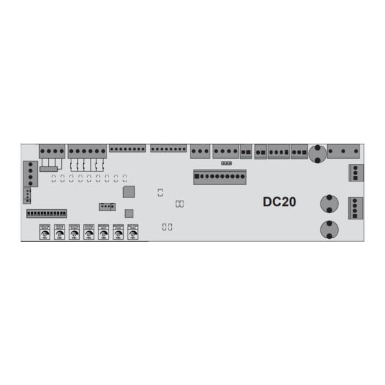
    LED DE DIAGNOSTIC led de signalisation DIAGNOSTIC DL2 - rouge led de signalisation ALIMENTATION INTERNE 12V DL3 - rouge led de signalisation ALIMENTATION INTERNE 5V DL4 - rouge led de signalisation ALIMENTATION AUXILIAIRES 24V CC DL5 - rouge led de signalisation RADAR INTÉRIEUR DL6 - rouge led de signalisation RADAR EXTÉRIEUR DL7 - vert...
  • Page 40: Dysfonctionnement Causes Possibles Et Solutions

    absorption moteur au-delà des limites jaune - 5 erreur direction moteur invertie jaune - 6 erreur jaune - 7 erreur jaune - 8 erreur DYSFONCTIONNEMENT CAUSES POSSIBLES ET SOLUTIONS PROBLÈME CAUSE PROBABLE SOLUTION La centrale n’a pas été soumise à Effectuer la procédure de ré- DL1 clignote vert/rouge al- la procédure d’initialisation (setup...
  • Page 41 DÉCLARATION D’INCORPORATION DU FABRICANT (conformément à la Directive européenne 2006/42/CE Annexe II.B) Fabricant : TAU S.r.l. Adresse : Via E. Fermi, 43 - 36066 Sandrigo (Vi) - ITALY Déclare sous sa propre responsabilité que le produit : Logique électronique de commande réalisé...
  • Page 42: Wichtige Hinweise

    Dieses Handbuch richtet sich ausschließlich an für die Installation qualifiziertes Fachpersonal. Keine der in diesen Unterlagen enthaltenen Informationen können als für den Endverbraucher von Interesse betrachtet werden. Dieses Handbuch liegt der Steuerung DC20 als Anlage bei und darf daher nicht für andere Produkte verwendet werden! Wichtige Hinweise: Vor dem Zugriff auf die Platine die Netzversorgung unterbrechen.
  • Page 43: Technische Merkmale

    ACHTUNG: - verwenden Sie keine einadrigen Kabel (mit nur einem Leiter), z. B. die für Sprechanlagen, um Unterbrechungen auf der Leitung und Fehlkontakte zu vermeiden; - verwenden Sie bereits vorhandene alte Kabel nicht erneut; ENDPRÜFUNG Nach dem Anschluss: • Die grünen Leds (DL7-8-9-11-12-13) müssen alle eingeschaltet sein (jede davon entspricht einem Öffnereingang).
  • Page 44 - Anschluss TLINETD Klemmen Eingang/Ausgang Beschreibung MINUSPOL VERSORGUNG T-LINETD - 5 V DC B SIGNAL T-LINETD Kommunikationssignal T-LINETD mit DC20 A SIGNAL T-LINETD Kommunikationssignal T-LINETD mit DC20 PLUSPOL VERSORGUNG T-LINETD + 5 V DC STECKVERBINDUNG J3 - Optionale Steckverbindung. STECKVERBINDUNG J4 - Versorgungsanschluss des externen Zubehörs.
  • Page 45 Geschlossen Keine. Beim Öffnen Keine. FOTOZELLE Beim Schließen Kehrt die Bewegung um und öffnet. 15 - 16 (Ausschaltglied) Die Tür schließt nicht, solange die Fotozellen belegt Geöffnet bleiben. In Pause Keine. TEST ANWESENHEITSDE- 17= + TEST 17 - 18 TEkTOR 18= - TEST STECKVERBINDUNG J16: Klemmen Eingang/Ausgang Türstatus...
  • Page 46: Beschreibung

    Die Tür öffnet sich nicht, solange der Eingang belegt Geschlossen bleibt. Beim Öffnen Stoppt die Automation. STOPP/ANTIPA- Beim Schließen Stoppt die Automation. 24 - 21 NIkFUNkTION (Opt.) Die Tür schließt sich nicht, solange der Eingang Geöffnet (NC) (21= Gemein) belegt bleibt. Die Tür öffnet sich nicht, solange der Eingang belegt In Pause bleibt.
  • Page 47 STECKVERBINDUNG J11 - Steckverbindung für Batterieladeplatine. STECKVERBINDUNG J12 - nicht verwendet. STECKVERBINDUNG J13 - Batteriesteckverbindung. STECKVERBINDUNG J14 - Steckverbindung für Primärkreis des Transformators. STECKVERBINDUNG J15 - Anschluss Versorgungseingang 230V 50Hz. STECKVERBINDUNG J6 - Steckverbindung für Sekundärkreis des Transformators. JUMPER J18 - Auswahl Encoderversorgung 12/5 VDC (auf 12 Vdc lassen wie werkseitig) STECKVERBINDUNG J15: Klemmen Eingang/Ausgang...
  • Page 48 • Nur mit entsprechenden Kabeln für den Kontrolltest ausgestattete Anwesenheitsdetektoren verwenden und diese an die Klemmen 17 und 18 der Steuerung DC20 anschließen; • Die Dip 11 und 12 von SW1 auf ON positionieren, um den Test zur Kontrolle der korrekten Funktionsweise zu aktivieren;...
  • Page 49 EINSTELLUNGEN DER LOGIKEN Trimmer Funktion Beschreibung GESCHWINDIGkEIT ÖFFNET Regelt die Öffnungsgeschwindigkeit. GESCHWINDIGkEIT SCHLIESST Regelt die Schließgeschwindigkeit. LEISTUNG ÖFFNEN Regelt die Stärke beim Öffnen. LEISTUNG SCHLIESSEN Regelt die Stärke beim Schließen. VERLANGSAMUNGSZEIT BEIM ÖFFNEN Regelt die Dauer der Verlangsamung beim Öffnen. VERLANGSAMUNGSZEIT BEIM Regelt die Dauer der Verlangsamung beim Schließen.
  • Page 50 Aktiviert den Test der internen Sensoren – der Test wird auf dem Eingang - und + ausgeführt TEST der Steckverbindung J19. 11 TEST INTERNE SENSOREN OFF Deaktiviert den Test auf dem Eingang der Steckverbindung J19. Aktiviert den Test der externen Sensoren – der Test wird auf dem Eingang - und + ausgeführt TEST der Steckverbindung J20.
  • Page 51 ACHTUNG: Sollten „Motor“-Alarme vorliegen, ist der Timer der automatischen Wiederherstellung unterdrückt. DIAGNOSE-LEDS Anzeige-Led DIAGNOSTIK DL2 - Rot Anzeige-Led INTERNE VERSORGUNG 12V DL3 - Rot Anzeige-Led INTERNE VERSORGUNG 5V DL4 - Rot Anzeige-Led VERSORGUNG HILFSGERÄTE 24V CC DL5 - Rot Anzeige-Led INTERNER RADAR DL6 - Rot Anzeige-Led EXTERNER RADAR DL7 - Grün...
  • Page 52 Motor defekt gelb - 4 Fehler Stromaufnahme des Motors über Grenzwerten gelb - 5 Fehler Motorrichtung umgekehrt gelb - 6 Fehler gelb - 7 Fehler gelb - 8 Fehler FUNKTIONSSTÖRUNGEN: MÖGLICHE URSACHEN UND BEHEBUNG PROBLEM CAUSA PROBABILE RIMEDIO Den in Absatz „Setup des Die Steuerung wurde nicht dem blinkt abwechselnd...
  • Page 53 Notfalleingang gesteuert werden. erzielt wird. INTEGRIERUNGSERKLÄRUNG DES HERSTELLERS (gemäß der Europäischen Richtlinie 2006/42/EG Anl. II.B) Hersteller: TAU S.r.l. Adresse: Via E. Fermi, 43 - 36066 Sandrigo (Vi) - ITALIA Erklärt unter seiner Haftung, dass das Produkt: Elektronische Steuerung für die automatische Bewegung von: Schiebetür für Fußgänger...
  • Page 54: Instalação

    Nenhuma informação contida neste documento pode ser considerada de interesse para o utiliza- dor final. Este manual de instalação diz respeito à unidade de controlo DC20. Não deve, portanto, ser usado para outros produtos diferentes! AVISOS IMPORTANTES : La logique de commande DC20 est destinée à...
  • Page 55: Características Técnicas

    Não utilizar cabos unifilares (como por exemplo cabos telefónicos) de modo a evitar interrupções na linha e falsos contactos; Não reutilizar cabos usados preexistentes; TESTE Após a conexão à rede eléctrica: • Os LEDs verdes (DL7-8-9-11-12-13) devem estar todos acesos (cada um corresponde a uma entrada normalmente fechada NC).
  • Page 56 Terminais Input/Output Descrição ALIMENTAÇÃO NEGATIVO T-LINETD - 5 V DC SINAL B T-LINETD Sinal de comunicação T-LINETD com DC20 SINAL A T-LINETD Sinal de comunicação T-LINETD com DC20 ALIMENTAÇÃO POSITIVA T-LINETD + 5 V DC TERMINAIS J3 - Opcional. TERMINAIS J4 - Alimentação dos acessórios externos.
  • Page 57 Fechada Abre nos modos "Apenas Entrada" e "Ambos os Sentidos" A abrir Nenhuma SENSOR Inverte o movimento e abre, nos modos "Apenas A fechar 15 - 16 EXTERIOR Entrada" e "Ambos os Sentidos" (N.A.) A porta não fecha até a zona de detecção do radar Aberta seja desimpedida Stand-by...
  • Page 58 A porta não abre enquanto o input; “STOP / ANTI- Fechada PÂNICO”; estiver activo A abrir Pára o automatismo A fechar Pára o automatismo STOP / ANTI-PÂNICO 24 - 21 A porta não fecha enquanto o input “STOP / ANTI- (N.C.) Aberta PÂNICO”...
  • Page 59 OUTPUT/SAÌDA INTERLOCK CONTATO INTERLOCK COMUM COMUM CONTATO INTERLOCK TERMINAIS J11 - Carregador de bateria. TERMINAIS J12 - Não utilizado. TERMINAIS J13 - Conexão para bateria. TERMINAIS J14 - Ligação ao primário do transformador. TERMINAIS J15 - Alimentação 230V 50 Hz. TERMINAIS J6 - Ligação ao secundário do transformador.
  • Page 60 • Utilizar somente detectores de presença equipados com cabos de teste apropriados, conec- tando-os aos terminais 17 e 18 da unidade de controlo DC20; • ajuste os dip switches #11 e #12 do SW1 para ON para habilitar o teste de funcionamento correcto;...
  • Page 61 AJUSTES LÓGICOS Trimmer Função Descrição VELOCIDADE Ajusta a velocidade de abertura ABERTURA VELOCIDADE Ajusta a velocidade de fecho FECHO POTêNCIA Ajusta a força na abertura ABERTURA POTêNCIA Ajusta a força no fecho FECHO TEMPO DE DESACELERAÇÃO NA Ajusta a duração da desaceleração na abertura BERTURA TEMPO DE DESACELERAÇÃO NO Ajusta a duração da desaceleração no fecho...
  • Page 62 Com a função INTERLOCK ACTIVA. Configurar como ON na unidade PRIORIDADE de controlo NÃO PRIORITÁRIA. DE ABERTURA Com a função INTERLOCK ACTIVA. Configurar como ON na unidade (INTERLOCK) de controlo PRIORITÁRIA. Habilita teste sensor interno. o teste é realizado na entrada - e + TESTE SENSOR TEST do conector J19.
  • Page 63: Led De Diagnóstico

    LED DE DIAGNÓSTICO DIAGNÓSTICO DL2 - Vermelho ALIMENTAÇÃO INTERNA 12V DL3 - Vermelho ALIMENTAÇÃO INTERNA 5V DL4 - Vermelho ALIMENTAÇÃO AUXILIAR 24V DC DL5 - Vermelho RADAR INTERNO DL6 - Vermelho RADAR EXTERNO DL7 - Verde FOTOCÉLULA 1 DL8 - Verde FOTOCÉLULA 2 DL9 - Verde EMERGêNCIA...
  • Page 64 Falha no motor Amarelo - 4 erro Corrente absorvida acima do limite Amarelo - 5 erro Direcção do motor invertida Amarelo - 6 erro Amarelo - 7 erro Amarelo - 8 erro AVARIAS: CAUSAS POSSíVEIS E SOLUçÃO PROBLEMA CAUSA POSSíVEL SOLUçÃO A unidade de controlo não foi sub- Execute o procedimento de...
  • Page 65 DECLARAÇÃO DE INCORPORAÇÃO DO FABRICANTE (Conforme directiva europeia 2006/42/CE Anexo AII. II.B) Fabricante: TAU S.r.l. Endereço: Via E. Fermi, 43 - 36066 Sandrigo (Vi) - ITALIA Declara sobre sua responsabilidade que o produto: Unidade de controlo Concebido para o movimento automático de: Portas de correr para utilização em ambiente:...
  • Page 66 Este manual está destinado sólo al personal técnico cualificado para la instalación. Ninguna información contenida en este manual puede ser considerada interesante para el usuario final. Este manual acompaña a la central DC20 por lo tanto, ¡no debe utilizarse para otro tipo de producto! Advertencias importantes: Corte la alimentación de red a la tarjeta antes de acceder a ella.
  • Page 67 interrupciones en la linea y falsos contactos; no utilizen cables viejos preexistentes. PRUEBA DE CONTROL Cuando la conexión se ha terminado: • Los Leds verdes (DL7-8-9-11-12-13) tienen que estar todos encendidos (cada uno de ellos corres- ponde a una entrada Normalmente Cerrada). Se apagan sólo cuando están afectados los mandos a los que están asociados.
  • Page 68 Abrazadera Entrada/Salida Descripcion ALIMENTACIÓN T-LINETD NEGATIVA - 5 V DC B SEñAL T-LINETD Señal de comunicación T-LINETD con DC20 A SEñAL T-LINETD Señal de comunicación T-LINETD con DC20 ALIMENTACIÓN T-LINETD POSITIVA + 5 V DC CONETOR J3 - Conetor opcional.
  • Page 69 Ninguna Cerrada En abertura Ninguna En cierre Invierte el movimiento y abre. 15 - 16 FOTOCELULA (N.C.) La puerta no se cierra hasta que las fotocélulas perma- Abierta necen ocupadas. En pausa Ninguna TEST DETECCION 17= + TEST 17 - 18 18= - TEST PRESENCIA CONETOR J16:...
  • Page 70 La puerta no se abre hasta que la entrada este Cerrada ocupada. En abertura Detiene la automatización. STOP/ANTIPANICO En cierre Detiene la automatización. 24 - 21 (Opz.) (NC) La puerta no cierra hasta que la entrada permanece Abierta (21= Comun) ocupada.
  • Page 71 CONTACTO INTERBLOQUEO SALIDA INTERBLOQUEO COMUN CONTACTO INTERBLOQUEO COMUN CONECTOR J11 - conector por tarjeta carigabateria. CONECTOR J12 - no utilizado. CONECTOR J13 - conector bateria. CONECTOR J14 - conector por primario del trasformador. CONECTOR J15 - conector entrada alimentacion 230V 50hz. CONNETTORE J6 - conector por secundario del trasformador.
  • Page 72 • Utilice únicamente detectores de presencia equipados con cables de control de prueba apropia- dos, conectándolos a las abrazaderas 17 y 18 de la central de control DC20; • ponga los interruptores DIP 11 y 12 de SW1 en ON para permitir que la prueba de control verifi...
  • Page 73 que el funcionamiento correcto; • La prueba se realiza al comienzo de cada maniobra (a excepción del movimiento hacia atrás). AJUESTES LOGICOS Trimmer Funcion Descripcion VELOCIDAD ABERTURA Ajusta la velocidad de apertura. VELOCIDAD CIERRE Ajusta la velocidad de cierre. FUERZA ABERTURA Ajusta la fuerza de apertura.
  • Page 74 Habilita prueba sensores internos: la prueba se realiza en la entrada PRUEBA SENSORES - y + TEST del conector J19. INTERNOS OFF Desactiva la prueba en la entrada del conector J19. Habilita prueba sensores externos: la prueba se realiza en la entrada PRUEBA SENSORES - y + TEST del conector J20.
  • Page 75: Diagnóstico Led

    DIAGNÓSTICO LED LED de señalización DIAGNÓSTICO DL2 - Rojo LED FUENTE DE ALIMENTACIÓN INTERNA 12V DL3 - Rojo LED FUENTE DE ALIMENTACIÓN INTERNA 5V DL4 - Rojo LED para señalización FUENTE DE ALIMENTACIÓN AUXILIAR 24V DC DL5 - Rojo LED para señalización de RADAR INTERNO DL6 - Rojo LED para señalización RADAR EXTERNO DL7 - Verde...
  • Page 76 amarillo - 7 error amarillo - 8 error MALFUNCIONES: POSIBLES CAUSAS Y SOLUCIONES PROBLEMA CAUSA PROBABLE SOLUCIÓN Realice el procedimiento de La unidad de control no ha sido DL1 parpadea alternativa- configuración inicial descrito sometida al procedimiento de ini- mente en verde / rojo. en el párrafo “Adjust recor- cialización (configuración de carrera) rido”.
  • Page 77 DECLARACIÓN DE INCORPORACIÓN DEL FABRICANTE (de acuerdo con la Directiva Europea 2006/42/CE Adj. II.B) Fabricante: TAU S.r.l. Dirección: Via E. Fermi, 43 - 36066 Sandrigo (Vi) - ITALY Declara bajo su propia responsabilidad que el producto: Central electrónica de control fabricado para el movimiento automático de:...
  • Page 80 Via Enrico Fermi, 43 - 36066 Sandrigo (VI) - Italy Tel +39 0444 750190 - Fax +39 0444 750376 info@tauitalia.com - www.tauitalia.com Foglietto illustrativo CARTA - Raccolta differenziata. Segui le indicazioni del tuo comune. (N.B.: togliere i punti metallici) Instruction leaflet PAPER - Waste separation.

Table des Matières