Table des Matières

Publicité

Les langues disponibles
  • FR

Les langues disponibles

Liens rapides

FRIGGITRICE GAS
GAS FRYER
GAS-FRITEUSE
FRITEUSE À GAZ
FREIDORA GAS
MANUALE D'USO E INSTALLAZIONE
USE AND INSTALLATION MANUAL
BEDIEN- UND INSTALLATIONSHANDBUCH
MANUEL D'UTILISATION ET D'INSTALLATION
MANUAL DE USO E INSTALACIÓN
0G1FR7G
1G1FR8G
Italiano
English
Deutsch
Français
Español
Ed. 0
03/2011
3161861
IT
GB
DE
FR
ES

Publicité

Table des Matières
loading

Sommaire des Matières pour Angelo Po 0G1FR7G

  • Page 1 FRIGGITRICE GAS GAS FRYER 0G1FR7G GAS-FRITEUSE 1G1FR8G FRITEUSE À GAZ FREIDORA GAS MANUALE D’USO E INSTALLAZIONE USE AND INSTALLATION MANUAL BEDIEN- UND INSTALLATIONSHANDBUCH MANUEL D’UTILISATION ET D’INSTALLATION MANUAL DE USO E INSTALACIÓN Italiano English Deutsch Français Español Ed. 0 03/2011...
  • Page 3: Table Des Matières

    INDICE rif. capitoli pag. 1 INFORMAZIONI GENERALI ..........2 2 INFORMAZIONI TECNICHE ..........4 3 SICUREZZA ............... 6 PARTE 4 USO E FUNZIONAMENTO ..........8 5 MANUTENZIONI .............. 11 6 GUASTI ................13 7 MOVIMENTAZIONE E INSTALLAZIONE ......14 8 REGOLAZIONI ..............19 PARTE 9 SOSTITUZIONE PARTI ...........
  • Page 4: Informazioni Generali

    INFORMAZIONI GENERALI RACCOMANDAZIONI PER IL LETTORE Per rintracciare facilmente gli argomenti specifici di parte: contiene tutte le informazioni ne- interesse, consultare l’indice analitico posto all’ini- cessarie ai destinatari omogenei, cioè tutti gli zio del manuale. operatori esperti e autorizzati a movimentare, Questo manuale è...
  • Page 5: Identificazione Costruttore E Apparecchiatura

    IDENTIFICAZIONE COSTRUTTORE E APPARECCHIATURA La targhetta di identificazione raffigurata, è applica- ) Tipo famiglia prodotto ta direttamente sull'apparecchiatura. In essa sono ) Tipo di gas riportati i riferimenti e tutte le indicazioni indispensa- ) Potenza dichiarata (kW) bili alla sicurezza di esercizio. ) Consumo gas Targa complementare ) Indicatore gas collaudo...
  • Page 6: Informazioni Tecniche

    In funzione delle esigenze di utilizzo, l'apparecchia- ra, è stata progettata e costruita per la frittura dei ci- tura è prodotta in più versioni (vedi figura). bi, nell'ambito della ristorazione professionale. 0G1FR7G (14 lt) 1G1FR8G (14+14 lt) IDM-39618900100.tif Organi principali A)Vasca di frittura: realizzata in acciaio inox.
  • Page 7: Dispositivi Di Sicurezza

    DISPOSITIVI DI SICUREZZA Anche se l'apparecchiatura è completa di tutti i di- spositivi di sicurezza, in fase di installazione e allac- ciamento essi dovranno, se necessario, essere integrati con altri in modo da rispettare le leggi vi- genti in materia. L'illustrazione indica la posizione dei dispositivi.
  • Page 8: Dotazione Accessori

    DOTAZIONE ACCESSORI Alla consegna viene fornita la seguente dotazione: A)Coperchio vasca. B)Cestelli. C)Prolunga scarico olio. IDM-39603312000.tif ACCESSORI A RICHIESTA A richiesta l'apparecchiatura può essere corredata dei seguenti accessori. A)Filtro olio B)"Kit" cestelli (KCFR7V) C)Raccoglitore olio D)Camino alto tipo A E)Camino alto tipo A con dispositivo di rompi- tiraggio antivento F) Kit trasformazione gas G)Kit per installazione "a ponte"...
  • Page 9 – Utilizzare l'apparecchiatura solo per gli usi previ- viduali (guanti, mascherine, occhiali, ecc.), come sti dal fabbricante. L'impiego dell'apparecchiatu- previsto dalle leggi vigenti in materia di sicurezza ra per usi impropri può recare rischi per la e salute, ogni volta che si effettua l'igienizzazione sicurezza e la salute delle persone e danni eco- e la pulizia dell'apparecchiatura con l'uso di pro- nomici.
  • Page 10: Uso E Funzionamento

    USO E FUNZIONAMENTO RACCOMANDAZIONI PER L'USO E FUNZIONAMENTO Importante L'incidenza degli infortuni derivanti cipali. Attuare solo gli usi previsti dal co- dall'uso di apparecchiature dipende da struttore manomettere nessun molti fattori che non sempre si riescono a dispositivo per ottenere prestazioni diverse prevenire e controllare.
  • Page 11 ACCENSIONE E SPEGNIMENTO BRUCIATORI Per l'accensione e lo spegnimento procedere nel modo indicato per entrambi i bruciatori. Accensione 1 - Aprire il rubinetto alimentazione gas. 2 - Premere e ruotare la manopola (A) in senso an- tiorario (pos. 1) e contemporaneamente agire ripetutamente sull'accensione piezoelettrica (B) per accendere la spia pilota.
  • Page 12: Inattività Prolungata Dell'apparecchiatura

    RIPRISTINO APPARECCHIATURA In caso di intervento del termostato di sicurezza è necessario ripristinare le condizioni iniziali di funzio- namento dell'apparecchiatura nel modo indicato. 1 - Lasciare raffreddare l'olio di 30-40°C. 2 - Aprire il portello (A). 3 - Premere il pulsante (B) del termostato di sicu- rezza intervenuto per riattivare l'alimentazione del gas.
  • Page 13: Manutenzioni

    – Usare periodicamente un polarimetro per misu- – Il massimo carico consigliato. per vasca, è di 0,9 rare la percentuale di composti polari (valore max consentito 25 g/100 g in conformità alla CIRCO- LARE MINISTERO DELLA SANITÀ n. 1 deII'11 gennaio 1991.
  • Page 14: Controllo Pressione Gas

    PULIZIA VASCA, CESTELLI E STRUTTURA REGGICESTELLI Per questa operazione procedere nel modo indica- 1 - Spegnere e lasciare raffreddare l'apparecchia- tura (vedi pag. 9). 2 - Chiudere il rubinetto alimentazione gas. 3 - Asportare e pulire i cestelli e la struttura reggi- cestelli (A).
  • Page 15: Ricerca Guasti

    GUASTI RICERCA GUASTI L'apparecchiatura, prima della messa in servizio, è dall’utilizzatore, per tutti gli altri è richiesta una pre- stata preventivamente collaudata. Le informazioni cisa competenza tecnica o particolari capacità e di seguito riportate hanno lo scopo di aiutare l'iden- quindi devono essere eseguiti esclusivamente da tificazione e correzione di eventuali anomalie e di- personale qualificato con esperienza riconosciuta e...
  • Page 16: Movimentazione E Installazione

    MOVIMENTAZIONE E INSTALLAZIONE RACCOMANDAZIONI PER LA MOVIMENTAZIONE E INSTALLAZIONE Importante Eseguire la movimentazione e l'installazio- ste operazioni dovrà, se necessario, orga- ne nel rispetto delle informazioni fornite dal nizzare "piano sicurezza" costruttore e riportate direttamente sull'im- salvaguardare l'incolumità delle persone ballo, sull'apparecchiatura e nelle istruzioni direttamente coinvolte.
  • Page 17: Movimentazione E Sollevamento

    MOVIMENTAZIONE E SOLLEVAMENTO L'apparecchiatura può essere movimentata con un dispositivo di sollevamento a forche o a gancio di portata adeguata. Prima di effettuare questa opera- zione, controllare la posizione del baricentro del ca- rico. Importante Nell'inserire il dispositivo di sollevamento, fare attenzione al tubo di alimentazione gas.
  • Page 18 MONTAGGIO APPARECCHIATURE IN BATTERIA Per montare le apparecchiature in batteria (fianco a fianco) procedere nel modo indicato. 1 - Sfilare le manopole (A). 2 - Svitare le viti (B) e smontare i cruscotti (C). 3 - Applicare, sui bordi da accostare, del nastro adesivo di protezione.
  • Page 19: Allacciamento Gas

    ALLACCIAMENTO GAS Importante Chi è autorizzato ad effettuare tale opera- zione deve possedere capacità ed espe- rienza acquisita e riconosciuta nel settore specifico, dovrà eseguire l'allacciamento a regola d'arte e tenere conto di tutti i requisi- ti normativi e legislativi. Ad allacciamento completato, prima di rendere operativa l'at- trezzatura, si dovrà...
  • Page 20: Collaudo Apparecchiatura

    ALLACCIAMENTO SCARICO FUMI Importante Importante Effettuare l'allacciamento nel rispetto delle L'accensione del ventilatore dell'impianto leggi vigenti in materia utilizzando il mate- di aspirazione forzata deve comportare riale appropriato e prescritto. l'apertura automatica del rubinetto di ali- mentazione gas. Allacciamento sotto cappa ad aspirazione for- zata Per questa operazione procedere nel modo indicato.
  • Page 21: Regolazioni

    REGOLAZIONI RACCOMANDAZINOI PER PER LE REGOLAZIONI Importante Prima di effettuare qualsiasi intervento di re, chiudere il rubinetto alimentazione gas regolazione, attivare tutti i dispositivi di si- ed impedire l'accesso a tutti i dispositivi curezza previsti e valutare la necessità di che potrebbero, se attivati, provocare con- informare adeguatamente il personale che dizioni di pericolo inatteso e di rischio per...
  • Page 22: Sostituzione Ugello Bruciatore

    SOSTITUZIONE UGELLO BRUCIATORE Per questa operazione procedere nel modo indica- 1 - Chiudere il rubinetto alimentazione gas. 2 - Aprire il portello (A). 3 - Svitare l'ugello (B) e sostituirlo con quello adat- to al tipo di gas utilizzato (vedi tabella in fondo al manuale).
  • Page 23 CONTENTS ref. chapters page 1 GENERAL INFORMATION ..........2 2 TECHNICAL INFORMATION ..........4 3 SAFETY ................6 PART 4 USE AND OPERATION ............. 8 5 SERVICING ..............11 6 FAULT................13 7 HANDLING AND INSTALLATION ......... 14 8 ADJUSTMENTS ............... 19 PART 9 REPLACING PARTS .............
  • Page 24: General Information

    GENERAL INFORMATION INFORMATION FOR THE READER To find the specific topics of interest to you quickly, 2nd part: contains all the information neces- refer to the index at the start of the manual. sary for special categories of reader, i.e. all This manual is subdivided into two parts.
  • Page 25: Procedure For Requesting Service

    IDENTIFICATION OF CONSTRUCTOR AND APPLIANCE The nameplate shown here is fitted directly to the ) Product family type ) Type of gas appliance. It contains references and all essential ) Rated power (kW) information for operating safety. ) Gas consumption Extra nameplate ) Testing gas indicator frame ) Country of use...
  • Page 26: Technical Information

    The appliance is produced in several versions to is designed and produced for frying foods in the meet varying user requirements (see diagram). professional catering sector. 0G1FR7G (14 lt) 1G1FR8G (14+14 lt) IDM-39618900100.tif Main Parts A)Frying well: in stainless steel.
  • Page 27: Safety Devices

    SAFETY DEVICES Although the appliance is complete with all safety devices, during installation and connection addi- tional devices must be added if necessary to com- ply with the relevant legal requirements. The illustration shows the position of the devices. A)Gas supply tap: for turning the connection to the gas supply line on and off.
  • Page 28: Standard Accessories

    STANDARD ACCESSORIES The appliance is delivered complete with the follow- ing: A)Well lid B)Baskets C)Oil drain extension IDM-39603312000.tif OPTIONAL ACCESSORIES The appliance can be equipped with the following accessories on request. A)Oil filter B)Basket (KCFR7) C)Oil drain container D)Type A tall fume exhaust vent E)Type A tall flue with draught damper device F) Gas conversion kit G)"Bridge"...
  • Page 29 – All servicing operations requiring specific techni- – At the end of each session of use, make sure that cal knowledge or skills must only be carried out the burners are off, with the control knobs turned by qualified staff with recognised experience in off and the gas supply lines disconnected.
  • Page 30: Use And Operation

    USE AND OPERATION RECOMMENDATIONS FOR USE Important The rate of accidents deriving from the use of tions. Use only as intended by the construc- appliances depends on many factors which tor and never tamper with any device to cannot always be foreseen and controlled. obtain performance levels outside the rated Some accidents may be caused by unpredict- specifications.
  • Page 31 SWITCHING THE BURNER ON AND OFF The lighting and turning off procedure is as de- scribed below for both burners. Lighting 1 - Turn on the gas supply tap. 2 - Press the knob (A) and turn it anti-clockwise (pos. 1) while at the same time pressing the pi- ezoelectric ignition knob (B) repeatedly to light the pilot light.
  • Page 32: Resetting The Appliance

    RESETTING THE APPLIANCE If the safety thermostat is tripped, the appliance has to be restored to the initial working conditions as fol- lows. 1 - Allow the oil to cool to 30-40°C. 2 - Open the hatch (A). 3 - Press the button (B) of the safety thermostat tripped to restore the gas supply.
  • Page 33: Servicing

    SERVICING RECOMMENDATIONS FOR SERVICING Keep the appliance at peak efficiency by carrying At the end of each session of use and whenever out the scheduled servicing procedures recom- necessary, clean: mended by the constructor. Proper servicing will al- – The well (see page 12) low the best performance, a longer working life and –...
  • Page 34: Checking Gas Pressure

    CLEANING WELL, BASKETS AND BASKET SUPPORT STRUCTURE To carry out this operation, proceed as follows. 1 - Switch the appliance off and leave it to cool (see page 9) 2 - Turn off the gas supply tap. 3 - Remove and clean the baskets and the basket support structure (A).
  • Page 35: Fault

    FAULT TROUBLESHOOTING The appliance has been tested before being put The user can solve some of these problems him- self, but for others specific technical knowledge or into service. skill is required, and so they must only be carried The information provided below is intended to as- out by qualified staff with recognised experience sist in the identification and correction of any anom- acquired in the specific sector of operation.
  • Page 36: Recommendations For Handling And Installation

    HANDLING AND INSTALLATION RECOMMENDATIONS FOR HANDLING AND INSTALLATION Important When handling and installing the appliance carry out these operations must organise a comply with the information provided by "safety plan" to protect the people directly the constructor directly on the packaging, involved.
  • Page 37: Handling And Lifting

    HANDLING AND LIFTING The appliance can be handled using fork-lift or hook equipment of suitable load-carrying capacity. Be- fore lifting, check the position of the load's centre of gravity. Important When engaging with the lifting equipment, watch out for the gas supply pipe. IDM-3960200190.tif INSTALLATION OF THE APPLIANCE All installation stages must be considered right from...
  • Page 38 ASSEMBLY APPLIANCES IN BANKS To assemble appliances in banks (side by side) proceed as described below. 1 - Pull off the knob (A). 2 - Undo the screws (B) and remove the control panels (C). 3 - Apply masking tape to the edges to be placed side by side.
  • Page 39: Gas Connection

    GAS CONNECTION Important Those authorised to carry out this opera- tion must have experience acquired and certified in the specific sector, must make the connection to the proper standards, and must comply with all the relevant regu- lations and legislation. Once the connec- tion has been made, before the appliance is put into operation a general check must be made to ensure there are no gas leaks.
  • Page 40: Testing Of The Appliance

    CONNECTION OF FUME EXHAUST VENT Important Important Make the connection in compliance with The gas supply tap must open automatical- ly when the fan of the extraction system is the relevant legal requirements, using ap- switched on. propriate and recommended materials. Connecting to a fan extractor hood To carry out this operation, proceed as follows.
  • Page 41: Adjustments

    ADJUSTMENTS RECCMANDATIONES FOR ADJUSTMENTS Important Before making any type of adjustment, acti- In particular, turn off the gas supply tap and vate all the safety devices provided and de- prevent access to all devices which might cide whether staff at work and those in the cause unexpected health and safety haz- vicinity should be informed.
  • Page 42: Replacement Of The Burner Nozzle

    REPLACEMENT OF THE BURNER NOZZLE To carry out this operation, proceed as follows. 1 - Turn off the gas supply tap. 2 - Open the hatch (A). 3 - Unscrew the nozzle (B) and replace it with the one suitable for the type of gas in use (see table at back of manual).
  • Page 43 INHALTSVERZEICHNIS Ref. Kapitel Seite 1 ALLGEMEINES..............2 2 TECHNISCHE INFORMATIONEN........4 3 SICHERHEIT ..............6 1. TEIL 4 GEBRAUCH UND BETRIEB ..........8 5 WARTUNG ............... 11 6 DEFEKTE ................. 13 7 HANDHABUNG UND INSTALLATION ......14 8 EINSTELLUNGEN ............19 2.
  • Page 44: Allgemeines

    ALLGEMEINES INFORMATIONEN FÜR DEN LESER Konsultieren Sie das Sachregister, das am Anfang des 2. Teil: Diese Informationen wenden sich an Handbuchs zu finden ist, um leichter unter bestimmten eine bestimmte Zielgruppe. Sie sind für erfahre- Themen von besonderem Interesse nachschlagen zu ne Bediener bestimmt, die für Handhabung, können.
  • Page 45: Typenschild Für Hersteller Und Gerät

    TYPENSCHILD FÜR HERSTELLER UND GERÄT Das abgebildete Typenschild wird direkt auf dem ) Gastyp ) Angabe der Leistung (Kw) Gerät aufgebracht. Es enthält sämtliche Angaben ) Gasverbrauch und Hinweise, die für den sicheren Betrieb unerläs- ) Testgasanzeige slich sind. ) Baujahr Ergänzungsschild Testgasschild ) Benutzerland...
  • Page 46: Technische Informationen

    Die Friteuse – im Folgenden als Gerät bezeichnet – Das Gerät wird bedarfsabhängig in verschiedenen wurde zum Frittieren von Speisen konzipiert und Versionen hergestellt (siehe Abbildung). gebaut und ist für Restaurationsbetriebe bestimmt. 0G1FR7G (14 lt) 1G1FR8G (14+14 lt) IDM-39618900100.tif Hauptorgane A)Frittierbecken: aus Edelstahl.
  • Page 47: Sicherheitsvorrichtungen

    SICHERHEITSVORRICHTUNGEN Das Gerät wird zwar mit sämtlichen planmäßigen Sicherheitsvorrichtungen geliefert, es kann jedoch notwendig sein, während Installation und An- schluss ggf. weitere ergänzende Maßnahmen zu ergreifen, um den Anforderungen der einschlägi- gen geltenden Gesetze zu entsprechen. Die Abbildung zeigt die Anordnung der Sicherheits- vorrichtungen.
  • Page 48: Optionales Zubehör

    ZUBEHÖRAUSSTATTUNG Bei der Übergabe wird folgende Ausstattung gelie- fert: A)Verschlussdeckel für Becken B)Korb C)Verlängerung des Ölabflussrohres IDM-39603312000.tif OPTIONALES ZUBEHÖR Auf Wunsch kann das Gerät mit folgenden Zube- hörteilen ausgestattet werden. A)Öfilter B)Körbe (KCFR7) C)Ölsammler D)Hoher Abzugskamin Typ A E)Hoher Kamin Typ A mit Zugunterbrecher bei Windbeeinflussung F) „Kit"...
  • Page 49 – Setzen Sie das Gerät nur für die vom Hersteller schriebene persönliche Schutzausrüstung vorgesehenen Verwendungszwecke ein. Der (Schutzhandschuhe, Atemschutzmaske, Schutz- missbräuchliche Einsatz Geräts kann brille usw.) tragen. schwerwiegende Gefahren für Sicherheit und – Stellen Sie nach jeder Verwendung sicher, dass Gesundheit von Personen und finanzielle Verlu- die Brenner ausgeschaltet sind, wobei die Bedi- ste hervorrufen.
  • Page 50: Gebrauch Und Betrieb

    GEBRAUCH UND BETRIEB EMPFEHLUNGEN FÜR DEN GEBRAUCH Wichtig Das Auftreten von Unfällen bei der Verwen- Sie sich auf die vom Hersteller vorgesehenen dung von Geräten hängt von vielen Faktoren Verwendungszwecke, ohne Änderungen an ab, die nicht immer zu vermeiden und zu steu- den Vorrichtungen vorzunehmen, um nicht ern sind.
  • Page 51 EIN- UND AUSSCHALTEN DES BRENNERS Verfahren Sie zum Zünden und Abschalten der bei- den Brenner folgendermaßen: Zündung 1 - Öffnen Sie den Gashahn. 2 - Drücken Sie auf den Knebel (A) und drehen Sie ihn im Gegenuhrzeigersinn (Pos. 1). Betätigen Sie gleichzeitig die piezoelektrische Zündung (B), um den Zündflammenbrenner einzuschal- ten.
  • Page 52: Rücksetzen Des Geräts

    RÜCKSETZEN DES GERÄTS Wenn der Sicherheitsthermostat anspricht, muss das Gerät in der angegebenen Weise wieder in den normalen Betriebszustand versetzt werden. 1 - Das Öl um 30-40°C abkühlen lassen. 2 - Öffnen Sie die Klappe (A). 3 - Den Taster (B) des ausgelösten Sicherheits- thermostaten drücken, um die Gaszufuhr wie- der freizugeben.
  • Page 53: Empfehlungen Für Die Wartung

    – Das Öl auswechseln, wenn es zwischen i 160-180 – Die maximale Zuladung beträgt 0,9 kg pro Bek- °C Rauch produziert oder wenn es eine dunkle ken. Farbe annimmt. – Regelmäßig mit einem Polarimeter den Anteil an polaren Bindungen prüfen. WARTUNG EMPFEHLUNGEN FÜR DIE WARTUNG Sorgen Sie dafür, dass das Gerät im Zustand maxima-...
  • Page 54 REINIGUNG BECKEN, KÖRBE UND KORBAUFHÄNGERGESTELL Für diesen Vorgang in der angegebenen Weise verfahren. 1 - Das Gerät ausschalten und abkühlen lassen (siehe Seite 9) 2 - Schließen Sie den Gaszufuhrhahn 3 - Die Körbe und das Korbaufhängergestell (A) herausnehmen und reinigen. 4 - Das Öl ablassen und filtrieren (siehe Seite 9) 5 - Ein geeignetes,...
  • Page 55: Defekte

    DEFEKTE FEHLERSUCHE Vor der Inbetriebnahme wurde das Gerät einem selbst behoben werden; alle anderen erfordern prä- vorläufigen Testlauf unterzogen. zise Fachkenntnisse oder besondere Fähigkeiten Die im Folgenden aufgeführten Informationen sol- und dürfen daher ausschließlich von qualifiziertem len Ihnen dabei helfen, eventuelle Anomalien oder Personal mit nachweislicher Erfahrung in diesem Funktionsstörungen, die während des Betriebs auf- speziellen Gebiet des Eingriffs durchgeführt wer-...
  • Page 56: Handhabung Und Installation

    HANDHABUNG UND INSTALLATION EMPFEHLUNGEN FÜR DIE INSTALLATION UND HANDHABUNG Wichtig Beachten Sie die Hinweise des Herstellers, nen autorisierte Person wird bei Bedarf die direkt auf der Verpackung, auf dem Ge- einen „Sicherheitsplan" aufstellen müssen, rät selbst oder in der Gebrauchsanweisung um die Unversehrtheit der direkt an dem zu finden sind, wenn Sie das Gerät handha- Vorgang beteiligten Personen zu gewähr-...
  • Page 57: Installation Des Geräts

    HANDHABUNG UND HUB Das Gerät kann mit einem Hubmittel bewegt wer- den, das mit Gabeln oder Haken ausgestattet ist und die geeignete Traglast besitzt. Vor diesem Vor- gang ist der Schwerpunkt der Last zu überprüfen. Wichtig Achten Sie beim Einsatz des Hubmittels auf das Gaszufuhrrohr.
  • Page 58 MONTAGE BEI REIHENAUFSTELLUNG Verfahren Sie folgendermaßen, um Geräte (neben- einander) in einer Reihe aufzustellen. 1 - Den Schalter (A) abziehen. 2 - Die Schrauben (B) ausschrauben und die Blen- den (C) ausbauen. 3 - Bekleben Sie die Gerätekanten, die nebenein- ander angeordnet werden sollen, mit einem Schutzband.
  • Page 59 GASANSCHLUSS Wichtig Diese Arbeit darf nur von zugelassenen und erfahrenen Fachleuten ausgeführt wer- den. Der Anschluss muss fachgerecht und vorschriftsmäßig ausgeführt werden und allen einschlägigen gesetzlichen Bestim- mungen entsprechen. Nach Ausführung des Anschlusses muss vor der Inbetrieb- nahme des Geräts durch eine allgemeine Kontrolle sichergestellt werden, dass nir- IDM-39611501300.tif gends Gas austritt.
  • Page 60 ANSCHLUSS DES RAUCHABZUGS Wichtig Wichtig Den Anschluss in Einklang mit den einschlä- Die Einschaltung des Ventilators der Ab- gigen gesetzlichen Bestimmungen und unter sauganlage musst das automatische Öff- Verwendung des hierfür geeigneten und vor- nen des Gashahns bewirken. geschriebenen Materials ausführen. Anschluss unter einer...
  • Page 61: Empfehlungen Für Die Einstellungen

    EINSTELLUNGEN EMPFEHLUNGEN FÜR DIE EINSTELLUNGEN Wichtig Vor Ausführung einer beliebigen Einstel- den Zugang zu allen Einrichtungen verhin- lung alle vorgesehenen Sicherheitseinrich- dern, die, wenn sie aktiviert werden, zur tungen einschalten Erwägung Entstehung von unerwarteten Gefahrensi- ziehen, ob eine angemessene Unterrich- tuationen führen und die Sicherheit und tung des ausführenden Personals und der Gesundheit von Personen beeinträchtigen...
  • Page 62 AUSWECHSELN DER BRENNERDÜSE Für diesen Vorgang in der angegebenen Weise verfahren. 1 - Schließen Sie den Gaszufuhrhahn. 2 - Öffnen Sie die Klappe (A). 3 - Schrauben Sie die Düse (B) heraus und erset- zen Sie sie mit dem für den betreffenden Gas- typ geeigneten Ersatzteil (siehe Tabelle am Ende des Handbuches).
  • Page 63: Index Analytique

    INDEX réf. chapitres page 1 INFORMATIONS GÉNÉRALES.......... 2 2 INFORMATIONS TECHNIQUES ........4 3 SÉCURITÉ ................. 6 PARTIE 4 UTILISATION ET FONCTIONNEMENT ......8 5 ENTRETIEN ..............11 6 PANNES ................13 7 MANUTENTION ET INSTALLATION ....... 14 8 RÉGLAGES ..............19 PARTIE 9 REMPLACEMENT DE PIÈCES ........
  • Page 64: Informations Générales

    INFORMATIONS GÉNÉRALES INFORMATIONS POUR LE LECTEUR Pour retrouver facilement les sujets qui vous inté- 2e partie: elle contient toutes les informa- ressent, consulter l’index analytique au début du tions nécessaires aux destinataires homogè- manuel. nes, c’est-à-dire tous les opérateurs experts Ce manuel est divisé...
  • Page 65: Identification Du Fabricant Et De L'appareil

    IDENTIFICATION DU FABRICANT ET DE L’APPAREIL La plaque d’identification représentée, est appli- ) Type de famille de produit ) Type de gaz quée directement sur l'appareil. Elle reporte les ré- ) Puissance déclarée (kW) férences et les indications indispensables à la ) Consommation de gaz sécurité.
  • Page 66: Informations Techniques

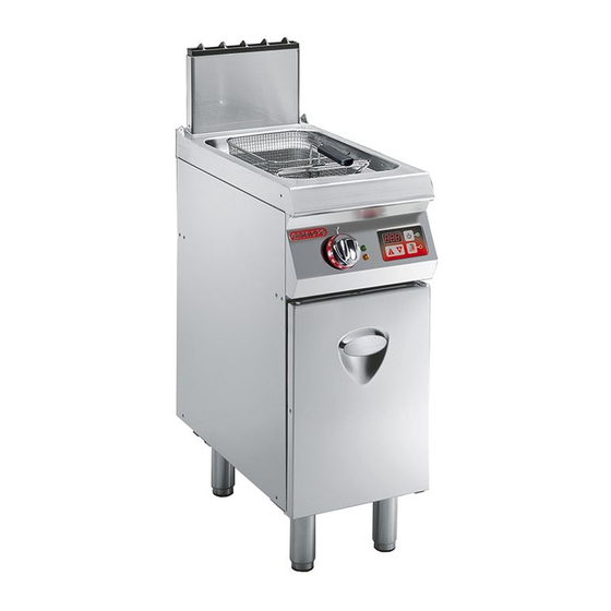
    En fonction des exigences d'utilisation, l'appareil a été conçue et fabriquée pour la friture d'aliments est réalisé en plusieurs versions (voir figure). dans le domaine de la restauration professionnelle. 0G1FR7G (14 lt) 1G1FR8G (14+14 lt) IDM-39618900100.tif Organes principaux A)Cuve de friture : en acier inox.
  • Page 67: Dispositifs De Sécurité

    DISPOSITIFS DE SÉCURITÉ Même si l’appareil est complet de tous les disposi- tifs de sécurité, lors de l’installation et du raccorde- ment, ils devront, si nécessaire, être intégrés avec d’autres pour respecter les lois en vigueur. L’illustration indique la position des dispositifs. A)Robinet d'alimentation du gaz: pour ouvrir et fermer le raccordement à...
  • Page 68: Dotation D'accessoires

    DOTATION D’ACCESSOIRES À la livraison sont fournis en équipement : A)Couvercle de la cuve B)Paniers C)Rallonge vidange de l’huile IDM-39603312000.tif ACCESSOIRES SUR DEMANDE Sur demande l'appareil peut être équipé des acces- soires suivants. A)Filtre de l’huile B)Panier (KCFR7) C)Récipient de recueil de l'huile D)Mitre haute type A E)Mitre haute type A avec dispositif coupe-vent F) «...
  • Page 69 – Utiliser l’appareil uniquement pour les usages – Porter les équipements de protection individuels prévus par le fabricant. L’utilisation de l’appareil (gants, masques, lunettes, etc.), comme prévu pour des usages impropres peut entraîner des par les lois en vigueur en matière de sécurité et risques pour la sécurité...
  • Page 70: Utilisation Et Fonctionnement

    UTILISATION ET FONCTIONNEMENT RECOMMANDATIONS POUR L'UTILISATION Important L'incidence des accidents dérivant de l'uti- les. Utiliser seulement comme prévu par le lisation d'appareils dépend de beaucoup de fabricant et ne modifier aucun dispositif facteurs que l'on ne peut pas toujours pré- pour obtenir des performances différentes venir et contrôler.
  • Page 71: Allumage Et Extinction Du Bruleur

    ALLUMAGE ET EXTINCTION DU BRULEUR Pour l’allumage et l’extinction des brûleurs, procé- der comme suit pour les deux brûleurs. Allumage 1 - Ouvrir le robinet d’alimentation du gaz. 2 - Presser et tourner la manette (A) en sens anti- horaire (pos. 1) et simultanément agir plusieurs fois sur l’allumage piézoélectrique (B) pour al- lumer la veilleuse pilote.
  • Page 72: Rétablissement Des Fonctions De L'appareil

    RÉTABLISSEMENT DES FONCTIONS DE L'APPAREIL Dans le cas d'intervention du thermostat de sécuri- té, il faut rétablir les conditions initiales de fonction- nement de l’appareil dans le mode indiqué. 1 - Laisser refroidir l’huile de 30-40°C. 2 - Ouvrir la porte (A). 3 - Appuyer sur le bouton (B) du thermostat de sé- curité...
  • Page 73: Recommandations Pour L'entretien

    – Remplacer l’huile si elle produit de la fumée entre – La charge maximale recommandée est de 0,9 Kg pour chaque cuve. 160-180° C ou lorsqu’elle devient foncée. – Mesurer régulièrement le pourcentage de com- posés polaires avec un polarimètre. ENTRETIEN RECOMMANDATIONS POUR L’ENTRETIEN Maintenir l'appareil en parfait état de fonctionne-...
  • Page 74: Contrôle De La Pression Du Gaz

    NETTOYAGE DE LA CUVE, DES PANIERS ET DE LA STRUCTURE DE SUPPORT Pour cette opération, procéder comme suit. 1 - Eteindre et laisser refroidir l’appareil (voir page 2 - Fermer le robinet d’alimentation du gaz. 3 - Enlever et nettoyer les paniers et la structure de support des paniers (A).
  • Page 75: Pannes

    PANNES DÉPANNAGE Avant sa mise en service, l’appareil a été essayé. l'utilisateur, pour tous les autres il faut une compé- Les informations reportées ci-après ont pour but tence technique précise ou des capacités particu- d’aider à l'identification et à la correction d’éven- lières;...
  • Page 76: Manutention Et Installation

    MANUTENTION ET INSTALLATION RECOMMANDATIONS POUR LA MANUTENTION ET L’INSTALLATION Important Effectuer la manutention et l’installation en effectuer ces opérations devra, si nécessai- respectant les informations fournies par le re, organiser un « plan de sécurité » pour fabricant, reportées directement sur l’em- sauvegarder la sécurité...
  • Page 77: Manutention Et Levage

    MANUTENTION ET LEVAGE L'appareil peut être manutentionné avec un dispo- sitif de levage à fourches ou à crochet d’une capa- cité de charge appropriée. Avant d’effectuer cette opération, contrôler la position du centre de gravité de la charge. Important En introduisant le dispositif de levage, faire attention au tuyau d’alimentation du gaz.
  • Page 78: Montage Des Appareils En Batterie

    MONTAGE DES APPAREILS EN BATTERIE Pour monter les appareils en batterie (les uns à côté des autres), procéder comme suit. 1 - Enlever la manette (A). 2 - Dévisser les vis (B) et démonter les tableaux de commandes (C). 3 - Appliquer, sur les bords à rapprocher, du ruban adhésif de protection.
  • Page 79: Raccordement Du Gaz

    RACCORDEMENT DU GAZ Important La personne autorisée à effectuer cette opération devra avoir les capacités et l'ex- périence acquise et reconnue dans le sec- teur spécifique; elle devra effectuer le raccordement dans les règles de l'art et te- nir compte de toutes les exigences impo- sées par les normes et les lois.
  • Page 80: Raccordement Évacuation Des Fumées

    RACCORDEMENT ÉVACUATION DES FUMÉES Important Important Effectuer le raccordement conformément L’allumage du ventilateur du système d’as- aux lois en vigueur à ce sujet en utilisant le piration forcée doit entraîner l’ouverture matériel approprié et prescrit. automatique du robinet d’alimentation gaz. Raccordement sous hotte à...
  • Page 81: Réglages

    RÉGLAGES RECOMMANDATIONS POUR LES RÉGLAGES Important Avant toute intervention de réglage, activer d'alimentation du gaz et empêcher l'accès à tous les dispositifs de sécurité prévus et tous les dispositifs qui pourraient, s'ils évaluer s'il est nécessaire d'informer le per- étaient activés, provoquer des conditions sonnel travaillant sur l'appareil et celui à...
  • Page 82: Remplacement De La Buse Du Brûleur

    REMPLACEMENT DE LA BUSE DU BRÛLEUR Pour cette opération, procéder comme suit. 1 - Fermer le robinet d’alimentation du gaz. 2 - Ouvrir la porte (A). 3 - Dévisser la buse (B) et la remplacer par celle adaptée au type de gaz utilisé (voir tableau à la fin du manuel).
  • Page 83 ÍNDICE ref. capítulos pág 1 INFORMACIONES DE CARÁCTER GENERAL ....2 2 INFORMACIONES DE CARÁCTER TÉCNICO ....4 3 SEGURIDAD..............6 PARTE 4 USO Y FUNCIONAMIENTO ..........8 5 MANTENIMIENTO ............11 6 AVERÍAS................13 7 DESPLAZAMIENTO E INSTALACIÓN ......14 8 REGULACIONES.............
  • Page 84: Informaciones De Carácter General

    INFORMACIONES DE CARÁCTER GENERAL INFORMACIONES PREVIAS Para ubicar fácilmente los temas específicos de in- 2a parte: contiene todas las informaciones ne- terés, consúltese el índice analítico que se encuen- cesarias para destinatarios homogéneos, esto tra al inicio del manual. es, todos los operadores expertos y autorizados Este manual comprende dos partes.
  • Page 85: Identificación Fabricante Y Equipo

    IDENTIFICACIÓN FABRICANTE Y EQUIPO La placa de identificación fijada directamente en el ) Tipo de gas ) Potencia declarada (kW) equipo reproduce todas las referencias e indicacio- ) Consumo de gas nes indispensables para la seguridad de servicio. ) Indicador gas prueba de funcionamiento Placa complementaria ) Fecha de fabricación ) País de uso...
  • Page 86: Informaciones De Carácter Técnico

    (véa- mentos en el sector de la restauración profesional. se figura). 0G1FR7G (14 lt) 1G1FR8G (14+14 lt) IDM-39618900100.tif Órganos principales A)Cuba de freído: fabricada en acero inox.
  • Page 87: Dispositivos De Seguridad

    DISPOSITIVOS DE SEGURIDAD Aunque el equipo cuente con todos los dispositivos de seguridad, en los casos en que así lo determi- nen las leyes vigentes en materia, se deberá com- plementar con otros dispositivos en las fases de instalación y enlace. La ilustración indica la posición de los dispositivos.
  • Page 88: Dotación De Accesorios

    DOTACIÓN DE ACCESORIOS El aparato se suministra equipado con los siguien- tes elementos: A)Tapa cuba B)Cestos C)Alargador descarga aceite IDM-39603312000.tif ACCESORIOS BAJO PEDIDO Bajo pedido, el equipo puede ser suministrado con los accesorios que a continuación se indican. A)Filtro aceite B)Cesto (KCFR14) C)Recogedor aceite D)Chimenea alta tipo A...
  • Page 89 – En el primer uso, incluso después de haberse so, después de cada uso del aparato. documentado adecuadamente, es conveniente – Al aplicar productos detergentes para la limpieza simular algunas maniobras de prueba, a fin de e higienización del aparato, deberán utilizarse identificar los mandos, especialmente los relati- siempre dispositivos de protección individual vos al encendido y apagado y sus principales...
  • Page 90: Uso Y Funcionamiento

    USO Y FUNCIONAMIENTO RECOMENDACIONES DE USO Importante El porcentaje de accidentes derivados del Se deben ejecutar sólo operaciones pro- uso de equipos depende de muchos facto- pias de los usos previstos por el fabricante. res que no siempre se logran prevenir y No alterar los equipos con el fin de obtener controlar.
  • Page 91 ENCENDIDO Y APAGADO DEL QUEMADOR Para el encendido y el apagado, efectuar en ambos quemadores las siguientes operaciones. Encendido 1 - Abrir el grifo de alimentación del gas. 2 - Para encender el testigo piloto, presionar y gi- rar el mando (A) en el sentido contrario al de las agujas del reloj (pos.
  • Page 92: Período Prolongado De Inactividad Del Equipo

    REACTIVACIÓN APARATO En caso de intervención del termostato de seguridad será necesario restablecer las condiciones iniciales de funcionamiento del aparato, procediendo para ello de la manera que a continuación se indica. 1 - Dejar enfriar el aceite en la medida de 30-40°C. 2 - Abrir la portezuela (A).
  • Page 93: Mantenimiento

    – Sustituir el aceite cuando produzca humo entre – Usar periódicamente un polarímetro para medir el porcentaje de compuestos polares. 160-180 °C, o bien cuando adquiera un color – La carga máxima recomendada es de 0,9 kilo- oscuro. gramos por cuba. MANTENIMIENTO RECOMENDACIONES PARA EFECTUAR EL MANTENIMIENTO Mantener el equipo en condiciones de máximo rendi-...
  • Page 94: Control De La Presión Del Gas

    LIMPIEZA CUBA, CESTOS Y SOPORTE DEL ENGANCHE CESTOS Para efectuar esta operación, aplicar las siguientes instrucciones. 1 - Apagar y dejar enfriar el aparato (véase pág. 9) 2 - Cerrar el grifo de alimentación del gas. 3 - Retirar y limpiar los cestos y el soporte del en- ganche cestos (A).
  • Page 95: Búsqueda De Averías

    AVERÍAS BÚSQUEDA DE AVERÍAS Antes de la puesta en servicio, el equipo ha sido so- por el usuario, pero otros requieren una competen- metido a prueba de funcionamiento. cia técnica precisa o determinadas capacidades, Las siguientes informaciones tienen por objeto faci- razón por la cual deben ser resueltos exclusiva- litar la identificación y corrección de eventuales mente por personal calificado con experiencia reco-...
  • Page 96: Desplazamiento E Instalación

    DESPLAZAMIENTO E INSTALACIÓN RECOMENDACIONES PARA EL DESPLAZAMIENTO Y LA INSTALACIÓN Importante Efectuar el desplazamiento e instalación re- da para efectuar estas operaciones deberá, spetando las indicaciones proporcionadas si fuera necesario, organizar un "plan de por el fabricante, reproducidas directamen- seguridad", a fin de salvaguardar la incolu- te sobre el embalaje, en el equipo y en las midad de las personas directamente invo- instrucciones de uso.
  • Page 97: Desplazamiento Y Elevación

    DESPLAZAMIENTO Y ELEVACIÓN El equipo puede ser desplazado con un equipo de elevación de horquillas o de gancho, de capacidad adecuada. Para ejecutar esta operación se debe controlar atentamente el centro de gravedad de la carga. Importante Proceder con cautela al introducir el equipo de elevación a fin de no dañar el tubo de ali- mentación del gas.
  • Page 98 MONTAJE DE EQUIPOS EN BATERÍA Para montar los equipos en batería (uno al lado del otro) aplicar las siguientes instrucciones. 1 - Retirar el mando (A). 2 - Desenroscar los tornillos (B) y desmontar los paneles de mando (C). 3 - Poner cinta adhesiva de protección sobre los bordes a juntar.
  • Page 99 ENLACE GAS Importante El personal autorizado para ejecutar esta operación debe poseer capacidad y haber adquirido experiencia efectiva en el sector específico; la conexión deberá ejecutarse respetando rigurosamente todos los requi- sitos establecidos por las normativas vi- gentes. Una vez efectuada la conexión, antes de poner en funcionamiento el apara- to se deberá...
  • Page 100: Conexión A La Salida De Humos

    CONEXIÓN A LA SALIDA DE HUMOS Importante Importante Llevar a cabo la conexión respetando las El ventilador de la instalación de aspiración leyes vigentes en materia y utilizar siempre forzada deberá encenderse automática- el material adecuado y previsto por el cons- mente tras la abertura de la llave de alimen- tructor.
  • Page 101: Regulaciones

    REGULACIONES RECOMENDACIONES PARA EFECTUAR LAS REGULACIONES Importante Antes de efectuar cualquier tipo de regula- de alimentación del gas e impedir el acceso ción, activar todos los dispositivos de se- a todos los dispositivos que, en caso de ser guridad previstos y evaluar la conveniencia activados, podrkan provocar situaciones de informar oportunamente tanto al perso- de peligro inesperado en cuanto a seguri-...
  • Page 102 SUSTITUCIÓN INYECTOR QUEMADOR Para efectuar esta operación, aplicar las siguientes instrucciones. 1 - Cerrar el grifo de alimentación del gas. 2 - Abrir la portezuela (A). 3 - Desenroscar el inyector (B) y sustituirlo por otro que sea adecuado para el tipo de gas utilizado (véase tabla al final del manual).
  • Page 103 Bruleur - Quemadores Model - Modelle Modèle - Modelo 7 kW G25.1 0G1FR7G N. 2 1,48 m 1,72 m 1,10 Kg/h 1,09 Kg/h SCHEDA ALLACCIAMENTI (0G1FR7G) - CONNECTION CARD (0G1FR7G) ANSCHLUSSSCHEMA (0G1FR7G) - FICHE DES RACCORDEMENTS (0G1FR7G) FICHA DE ENLACES (0G1FR7G) IDM-39618901500.tif...
  • Page 104 Bruciatori Consumo gas Burner - Brenner Gas consumption - Gasverbrauch Modello Consommation de gaz - Consumo de gas Bruleur - Quemadores Model - Modelle Modèle - Modelo 7 kW 1G1FR8G N. 4 2,96 m 3,45 m 2,21 Kg/h 2,18 Kg/h SCHEDA ALLACCIAMENTI (1G1FR8G) - CONNECTION CARD (1G1FR8G) ANSCHLUSSSCHEMA (1G1FR8G) - FICHE DES RACCORDEMENTS (1G1FR8G) FICHA DE ENLACES (1G1FR8G)
  • Page 105 Tabella iniettori bruciatore (0G1FR7G) - Burner injector table (0G1FR7G) - Tabelle der Brennerdüsen (0G1FR7G) Tableau des injecteurs des brûleurs (0G1FR7G) - Tabla inyectores quemador (0G1FR7G) Pen mbar Qn max P (3) mbar ø (4) ø (5) ø (6) Qn min P (7) mbar ø...
  • Page 106 Tabella iniettori bruciatore (0G1FR7G) - Burner injector table (0G1FR7G) - Tabelle der Brennerdüsen (0G1FR7G) Tableau des injecteurs des brûleurs (0G1FR7G) - Tabla inyectores quemador (0G1FR7G) Pen mbar Qn max P (3) mbar ø (4) ø (5) ø (6) Qn min P (7) mbar ø...
  • Page 107 Tabella iniettori bruciatore (0G1FR7G) - Burner injector table (0G1FR7G) - Tabelle der Brennerdüsen (0G1FR7G) Tableau des injecteurs des brûleurs (0G1FR7G) - Tabla inyectores quemador (0G1FR7G) Pen mbar Qn max P (3) mbar ø (4) ø (5) ø (6) Qn min P (7) mbar ø...
  • Page 108 Tabella iniettori bruciatore (1G1FR8G) - Burner injector table (1G1FR8G) - Tabelle der Brennerdüsen (1G1FR8G) Tableau des injecteurs des brûleurs (1G1FR8G) - Tabla inyectores quemador (1G1FR8G) Pen mbar Qn max P (3) mbar ø (4) ø (5) ø (6) Qn min P (7) mbar ø...
  • Page 109 Tabella iniettori bruciatore (1G1FR8G) - Burner injector table (1G1FR8G) - Tabelle der Brennerdüsen (1G1FR8G) Tableau des injecteurs des brûleurs (1G1FR8G) - Tabla inyectores quemador (1G1FR8G) Pen mbar Qn max P (3) mbar ø (4) ø (5) ø (6) Qn min P (7) mbar ø...
  • Page 110 Tabella iniettori bruciatore (1G1FR8G) - Burner injector table (1G1FR8G) - Tabelle der Brennerdüsen (1G1FR8G) Tableau des injecteurs des brûleurs (1G1FR8G) - Tabla inyectores quemador (1G1FR8G) Pen mbar Qn max P (3) mbar ø (4) ø (5) ø (6) Qn min P (7) mbar ø...
  • Page 111 Tabella caratteristiche gas - Table of gas characteristics - Tabelle der Gas-Eigenschaften Tableau des caractéristiques du gaz - Tabla características gas Potere calorifero inferiore (Hi) Famiglia Tipo di gas Indice Wobbe (MJ/m Net calorific value (Hi) Group Gas type Wobbe index (MJ/m Unterer Heizwert (Hi) Familie Gastypen...

Ce manuel est également adapté pour:

1g1fr8g

Table des Matières