Télécharger Imprimer la page

Publicité

Les langues disponibles
  • FR

Les langues disponibles

  • FRANÇAIS, page 53

Liens rapides

VMM501
USER MANUAL
HANDLEIDING
MODE D'EMPLOI
MANUAL DEL USUARIO
BEDIENUNGSANLEITUNG
INSTRUKCJA OBSŁUGI
MANUAL DO UTILIZADOR
MOTOR SHIELD FOR MICRO:BIT
2
27
53
79
107
136
162

Publicité

loading

Sommaire des Matières pour Velleman VMM501

  • Page 1 VMM501 MOTOR SHIELD FOR MICRO:BIT USER MANUAL HANDLEIDING MODE D'EMPLOI MANUAL DEL USUARIO BEDIENUNGSANLEITUNG INSTRUKCJA OBSŁUGI MANUAL DO UTILIZADOR...
  • Page 2  Nor Velleman nv nor its dealers can be held responsible for any damage (extraordinary, incidental or indirect) – of any nature (financial, physical…) arising from the possession, use or failure of this product.
  • Page 3 VMM501 Description This starter kit is an educational kit based on micro:bit. It comes with basic electronic components, a breadboard, connection wires and a micro:bit. Examples 1x micro:bit board 1x micro:bit breadboard adapter 1x breadboard 2x red LED (polarisation: anode (+) = long leg, cathode (-) = short leg) 2x 100 Ω...
  • Page 4 VMM501 What is MakeCode? Formerly PXT – Programming eXperience Toolkit Editor to write code for the micro:bit. A graphical, beginner-friendly drag-and-drop code editor similar to Scratch. It works online, in the browser. You can see the editor is made up of different sections. You make your code in the...
  • Page 5 VMM501 Options Bar Click to create or add a new project. Import your projects here. Open up the Blocks interface to write your scripts with the Block editor. Open up the Javascript interface to type out your script in the Javascript language.
  • Page 6 VMM501 Select Click to edit Drag See what happens in the micro:bit simulator! Say Hello! The text you have been displaying are called strings. You can show any integer in the LED screen using show number or any 5x5 pixel image using show leds.
  • Page 7 VMM501 Testing on micro:bit Connect the micro;bit to your computer using a micro-USB cable. It will go through a default sequence, asking you to press buttons and play a game. Try it out! Click Download to translate your script to a hex file and to download it.
  • Page 8 VMM501 Button 1x micro:bit board 1x micro:bit breadboard adapter 1x breadboard 2x red LED (polarisation: anode (+) = long leg, cathode (-) = short leg) 2x 100 Ω resistor (brown/black/brown/gold) 1x momentary push button We use a button to control the LED flash. Press the button to make the LED flash in turns.
  • Page 9 VMM501 Set P2 to be a pull-up. Set the digital read pin to P2. Set the digital write pin 0 (active low (0 V)). Set the digital write pin 1 (active high (5 V)). Set the pause to 500 ms.
  • Page 10 VMM501 Have a look at the code below. Drag and drop the code blocks to form the code as shown. You can find the plot bar graph of up to 0 block in in the Code Drawer. analog read pin to P0.
  • Page 11 VMM501 Have a look at the code below. First, we make two variables. Go to Variables in the Code Drawer and click Make a Variable. Enter CalVal in the window and click Ok. Enter PhoVal in the window and click Ok.
  • Page 12 VMM501 In the forever block, select the PhoVal variable and set the analog read to P0. Drag the logic smaller than function next to the block and drop it over true block. Next, we drag and drop the PhoVal variable (from...
  • Page 13 VMM501 When complete, we compile the programme and generate a hex. file. Click on the download button and save the hex. file to the Downloads folder  C:\downloads. This hex. file is ready to upload to the micro:bit. Plug the micro:bit into a USB port. The, drag and drop the hex. file onto the micro:bit removable device to upload the programme.
  • Page 14 VMM501 Have a look at the code below. Drag and drop the code blocks to form the code as shown. You can find the on button pressed block in Input in the Code Drawer. You can find the digital write pin...
  • Page 15 VMM501 Similarly, compile the two on button B/A+B pressed blocks to form the complete code. When complete, we compile the programme and generate a hex. file. Click on the download button and save the hex. file to the Downloads folder ...
  • Page 16 VMM501 Drag and drop the code blocks to form the code as shown. You can find the set pin P0 to emit edge events set pull P0 to up blocks in Pins More in the Code Drawer. You can find the on event ...
  • Page 17 VMM501 Have a look at the code below. Drag and drop the code blocks to form the code as shown. You can find the set item to block in Variables in the Code Drawer. You can find the map/from low/from high/to low/to high...
  • Page 18 VMM501 Drag and drop the analog read pin block next to the map/from low/from high/to low/to high block and set the to high value 4 to 3300. Now, we drag and drop a set item to block under the first block. Change...
  • Page 19 VMM501 Drag and drop the mathematical function minus over the first 0 of the mathematical function divide. Now, set the second variable from to tem, and drag and drop the variable over the first 0 of the mathematical function minus. The...
  • Page 20 VMM501 Finally, drag and drop the variable over the value 0 of the show number block. You have written the code! When complete, we compile the programme and generate a hex. file. Click on the download button and save the hex. file to the Downloads folder ...
  • Page 21 VMM501 Drag and drop the code blocks to form the code as shown. You can find the servo write pin 180 block in Pins in the Code Drawer. You can find the forever pause (ms) 100 in Basic in the Code Drawer.
  • Page 22 VMM501 Have a look at the code below. Drag and drop the code blocks to form the code as shown. You can find the forever pause (ms) 100 in Basic in the Code Drawer. You can find the ring tone (Hz)
  • Page 23 VMM501 5.10 Motor 1x micro:bit board 1x micro:bit breadboard adapter 1x breadboard 1x diode 1x 100 Ω resistor (brown/black/brown/gold) 1x self-locking or bi-stable switch 1x N-channel MOSFET 1x mini motor 1x battery holder with 2x AA 1.5 V battery We are going to use a switch to control the start and stop of a motor.
  • Page 24 VMM501 Within forever, set the digital read pin to P1. Set the mathematical function equal to 0. In reality, this is the scheme. The pull-up resistor must not be added as hardware onto the breadboard. The pull-up function is programmed (see step 3-4) in the code and replaces the need of the resistor on the breadboard.
  • Page 25 VMM501 Have a look at the code below. Drag and drop the code blocks to form the code as shown. Search and add the NeoPixel library. Go to Advanced  Add Package (Extensions) and enter NeoPixel. Next, select the NeoPixel library.
  • Page 26 © COPYRIGHT NOTICE The copyright to this manual is owned by Velleman nv. All worldwide rights reserved. No part of this manual may be copied, reproduced, translated or reduced to any electronic medium or otherwise without the prior written consent of the copyright holder.
  • Page 27  Noch Velleman nv noch zijn verdelers kunnen aansprakelijk gesteld worden voor schade (buitengewoon, incidenteel of onrechtstreeks) – van welke aard dan ook (financieel, fysisch…) voortvloeiend uit het bezit, gebruik of falen van dit product.
  • Page 28 VMM501 Omschrijving Deze starterskit is een educatieve kit gebaseerd op micro:bit. Deze kit wordt geleverd met elektronische componenten, een breadboard, aansluitkabels en een micro:bit. Voorbeelden micro:bit board 1x micro:bit breadboard adapter 1 x breadboard 2x rode led (polarisatie: anode (+) = lang pootje, kathode (-) = kort pootje) 2x 100 Ω...
  • Page 29 VMM501 Wat is MakeCode? Eerdere naam PXT – Programming eXperience Toolkit Editor om codes te schrijven voor de micro:bit. Een grafische en beginnersvriendelijke drag-and-drop code-editor vergelijkbaar met Scratch, die online werkt in de browser. U kunt zien dat de editor uit verschillende secties bestaat. Maak uw code in het codeveld, door blokken te...
  • Page 30 VMM501 Optiebalk Klik om een nieuw project te maken of toe te voegen. Importeer hier uw projecten. Klik op Blocks om scripts te schijven met de Block-editor. Klik op Javascript om uw script om te zetten in Javascript. Klik op het vraagteken voor meer informatie over de verschillende blokken en functies.
  • Page 31 VMM501 De ledmatrix gebruiken We beginnen met het schrijven van de code! Telkens u klikt op een blok uit het menu, wordt een lijst met alle beschikbare codes weergegeven. Sleep het blok show string uit het menu en klik in het blok om te bewerken.
  • Page 32 VMM501 Blokken samenvoegen Klik op het blokje dat u wilt samenvoegen. Sleep het blok naar het doelblok totdat de zijkant van het doelblok oplicht. Laat los en de twee blokjes zijn samengevoegd! Als u op het eerste blok klikt, wordt het tweede verplaatst. Als u op het tweede blokje klikt, wordt deze van het eerste losgekoppeld.
  • Page 33 VMM501 Sleep de blokken om de code te maken (zie afb.). Het blok digital write pin 0 bevindt zich in het menu onder Advanced  Pins. De blokken forever pause (ms) 100 bevinden zich in het menu onder Basic. Stel de waarde voor P0 in op 0. LED0 off = low voltage = 0 V = digital 0.
  • Page 34 VMM501 Knop 1x micro:bit board 1x micro:bit breadboard adapter 1 x breadboard 2x rode led (polarisatie: anode (+) = lang pootje, kathode (-) = kort pootje) 2x 100 Ω weerstand (bruin/zwart/bruin/goud) 1x drukschakelaar met momentcontact Een knop wordt gebruikt om de knipperende leds te bedienen.
  • Page 35 VMM501 Stel P2 in als een pull-up weerstand. Stel digital read pin in op P2. Stel digital write pin in op 0 (laag-actief (0 V)). Stel digital write pin in op 1 (hoog-actief (5 V)). Stel de pauze in op 500 ms.
  • Page 36 VMM501 Bekijk de onderstaande code. Sleep de blokken om de code te maken (zie afb.). Het blok plot bar graph of up to 0 bevindt zich in het menu onder LED. Stel analog read pin in op P0. Dit blok bevindt zich in het menu onder Pins.
  • Page 37 VMM501 Bekijk de onderstaande code. Eerst maken we twee variabelen. Ga naar Variables in het menu en klik op Make a Variable. Voer CalVal in het veld in en klik op Ok. Voer PhoVal in het veld in en klik op Ok.
  • Page 38 VMM501 In het blok forever, selecteer de variabele PhoValen stel analog read pin in op P0. Sleep het blok logic smaller than function (<)naast het blok en sleep het over het blok true. Sleep de variabele PhoVal (vanaf het menu onder Variables) over de...
  • Page 39 VMM501 Compileer het programma en sla het op als een .hex-bestand. Klik op de knop Download en sla het .hex-bestand op in de map Downloads  C:\downloads. Dit .hex-bestand kan naar de micro:bit geüpload worden. Sluit de micro:bit aan op een USB-poort. Sleep het .hex-bestand naar de micro:bit [removable device] om het programma te uploaden.
  • Page 40 VMM501 Bekijk de onderstaande code. Sleep de blokken om de code te maken (zie afb.). Het blok on button pressed bevindt zich in het menu onder Input. Het blok digital write pin 0 bevindt zich in het menu onder Pins.
  • Page 41 VMM501 Compileer het programma en sla het op als een .hex-bestand. Klik op de knop Download en sla het .hex-bestand op in de map Downloads  C:\downloads. Dit .hex-bestand kan naar de micro:bit geüpload worden. Sluit de micro:bit aan op een USB-poort. Sleep het .hex-bestand naar de micro:bit [removable device] om het programma te uploaden.
  • Page 42 VMM501 Sleep de blokken om de code te maken (zie afb.). De blokken set pin P0 to emit edge events set pull P0 to up bevinden zich in het menu onder Pins  More. De blokken on event from MICROBIT…EVT_FALL/RISE bevinden zich in het menu onder Control.
  • Page 43 VMM501 Bekijk de onderstaande code. Sleep de blokken om de code te maken (zie afb.). Het blok set item to bevindt zich in het menu onder Variables. De blokken map/from low/from high/to low/to high analog read pin bevinden zich in het menu onder Pins. De blokken...
  • Page 44 VMM501 Sleep het blok analog read pin naast het blok map/from low/from high/to low/to highen stel waarde 4 to high in op 3300. Sleep een blok set item to onder het eerste blok. Wijzig de variabele item met de pijl.
  • Page 45 VMM501 Sleep het blok mathematical function minus (-)over de eerst 0 van de mathematical function divide (/). Stel nu de tweede variabele van in op en sleep de variabele over de eerste waarde 0 van de wiskundige functie minus (-). De variabele bevindt zich in het menu onder Variables.
  • Page 46 VMM501 U hebt net de code geschreven! Compileer het programma en sla het op als een .hex-bestand. Klik op de knop Download en sla het .hex-bestand op in de map Downloads  C:\downloads. Dit .hex-bestand kan naar de micro:bit geüpload worden.
  • Page 47 VMM501 Sleep de blokken om de code te maken (zie afb.). Het blok servo write pin 180 bevindt zich in het menu onder Pins. De blokken forever pause (ms) 100 bevinden zich in het menu onder Basic. Stel P0 in op P1 en stel de waarde in op 0.
  • Page 48 VMM501 Bekijk de onderstaande code. Sleep de blokken om de code te maken (zie afb.). De blokken forever pause (ms) 100 bevinden zich in het menu onder Basic. Het blok ring tone (Hz) bevindt zich in het menu onder Music.
  • Page 49 VMM501 5.10 Motor 1x micro:bit board 1x micro:bit breadboard adapter 1 x breadboard 1x diode 1x 100 Ω weerstand (bruin/zwart/bruin/goud) 1x zelfvergrendelende of bistabiele schakelaar 1x N-kanaal MOSFET 1x mini motor 1x batterijhouder met 2x AA 1.5 V-batterij In het voorbeeld hieronder gebruiken we een schakelaar om de motor aan te sturen (starten-stoppen).
  • Page 50 VMM501 Stel digital read pin in op P1in het blok forever. Stel de wiskundige functie gelijk aan in op 0. In feite is dit het schema. U moet de pull-up-weerstand niet op het breadboard aansluiten. De pull-up-functie is geprogrammeerd (zie stappen 3-4) in de code en is een weerstand op het breadboard niet nodig.
  • Page 51 VMM501 Bekijk de onderstaande code. Sleep de blokken om de code te maken (zie afb.). Zoek en voeg de NeoPixel-bibliotheek toe. Ga naar Advanced  Add Package (Extensions) en geef NeoPixel in. Selecteer de NeoPixel-bibliotheek. De bibliotheek is gedownload en aan het menu toegevoegd.
  • Page 52 De leds creëren een regenboogeffect op de ledring. Hoe zou u de ring nu als een oog laten knipperen? Gebruik dit toestel enkel met originele accessoires. Velleman nv is niet aansprakelijk voor schade of kwetsuren bij (verkeerd) gebruik van dit toestel. Voor meer informatie over dit product en de laatste versie van deze handleiding, zie www.velleman.eu.
  • Page 53  Ni Velleman SA ni ses distributeurs ne peuvent être tenus responsables des dommages exceptionnels, imprévus ou indirects, quelles que soient la nature (financière, corporelle, etc.), causés par la possession, l’utilisation ou le dysfonctionnement de ce produit.
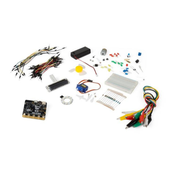
  • Page 54 VMM501 Description Ce kit de démarrage est un kit éducatif basé sur micro:bit. Le kit comporte des composants de base électroniques, une platine d'expérimentation, des câbles de connexion et un micro:bit. Exemples 1x carte micro:bit 1x adaptateur pour platine d'expérimentation micro:bit 1x platine d'expérimentation...
  • Page 55 VMM501 Qu’est-ce que MakeCode ? (Auparavant PXT – Programming eXperience Toolkit). Un éditeur de code graphique par glisser-déposer convivial pour débutants, similaire à Scratch, qui fonctionne en ligne dans le navigateur. L'éditeur se compose en différent volets : Le code est créé dans la...
  • Page 56 VMM501 Barre d'options Cliquer pour créer ou ajouter un nouveau projet. Cliquer sur Import pour importer vos projets. Cliquer sur Blocs pour écrire votre script avec l'éditeur Block. Cliquer sur Javascript pour écrire votre script en JavaScript. Cliquer sur le point d'interrogation pour accéder au menu d'aide.
  • Page 57 VMM501 Sélectionner Cliquer pour modifier Glisser-déposer Tester le code dans le simulateur ! Say Hello! Les caractères affichés sont des chaînes de caractères. Vous pouvez afficher du texte et des numéros en utilisant la fonction show number ou une image de 5x5...
  • Page 58 VMM501 Assembler les blocs Cliquer et maintenir enfoncé le bouton gauche de la souris pour faire glisser le bloc. Faire glisser le bloc vers le bloc cible jusqu'à ce que le bord du bloc s'illumine. Déposer le bloc et les deux blocs s'emboîtent ! Cliquer sur le premier bloc pour déplacer le deuxième bloc.
  • Page 59 VMM501 Glisser-déposer les blocs pour former le code comme indiqué. Le bloc digital write pin 0 se trouve dans le menu sous Advanced  Pins. Les blocs forever pause (ms) 100 se trouvent dans le menu sous Basic. Régler la valeur pour P0 sur 0. LED0 off = low voltage = 0 V = digital 0.
  • Page 60 VMM501 Bouton 1x carte micro:bit 1x adaptateur pour platine d'expérimentation micro:bit 1x platine d'expérimentation 2x LED rouge (polarisation : anode (+) = patte longue, cathode (-) = patte courte) 1x résistance 100 Ω (marron/noir/marron/or) 1x interrupteur à action momentanée Nous utilisons un bouton pour contrôler le clignotement de la LED.
  • Page 61 VMM501 Faire glisser le bloc digital read pin P0 et déposer le sur le 0 du bloc de la fonction logic equal function (=) (voir ill.). Configurer P2 comme une résistance pull-up. Régler digital read pin sur P2. Régler digital write pin 0 (actif bas (0 V)).
  • Page 62 VMM501 Regarder le code ci-dessous. Glisser-déposer les blocs pour former le code comme indiqué. Le bloc plot bar graph of up to 0 se trouve dans le menu sous LED. Régler analog read pin sur P0. Ce bloc se trouve dans le menu sous Pins.
  • Page 63 VMM501 Regarder le code ci-dessous. Tout d'abord, créons deux variables. Aller à Variables dans le menu et cliquer sur Make a Variable. Entrer CalVal dans la case et cliquer sur Ok. Entrer PhoVal dans la case et cliquer sur Ok.
  • Page 64 VMM501 Dans le bloc forever, sélectionner la variable PhoVal et régler le bloc analog read pin sur P0. Faire glisser la fonction smaller than (<) à côté du bloc et déposer le sur le bloc true. Faire glisser la variable...
  • Page 65 VMM501 Une fois terminé, compiler le programme pour générer un fichier .hex. Cliquer sur le bouton Download/Télécharger et sauvegarder le fichier .hex dans le dossier Downloads  C:\downloads. Ce fichier .hex peut être téléversé vers le micro:bit. Connecter le micro:bit à un port USB. Glisser-déposer le fichier .hex sur le micro:bit [Removable device] pour téléverser le programme.
  • Page 66 VMM501 Regarder le code ci-dessous. Glisser-déposer les blocs pour former le code comme indiqué. Le bloc on button pressed se trouve dans le menu sous Input. Le bloc digital write pin 0 se trouve dans le menu sous Pins. Sélectionner l'option A dans le bloc on button A pressed.
  • Page 67 VMM501 Une fois terminé, compiler le programme pour générer un fichier .hex. Cliquer sur le bouton Download/Télécharger et sauvegarder le fichier .hex dans le dossier Downloads  C:\downloads. Ce fichier .hex peut être téléversé vers le micro:bit. Connecter le micro:bit à un port USB. Glisser-déposer le fichier .hex sur le micro:bit [Removable device] pour téléverser le programme.
  • Page 68 VMM501 Glisser-déposer les blocs pour former le code comme indiqué. Les blocs set pin P0 to emit edge events set pull P0 to up trouvent dans le menu sous Pins  More. Les blocs on event from MICROBIT…EVT_FALL/RISE se trouvent dans le menu sous Control.
  • Page 69 VMM501 Regarder le code ci-dessous. Glisser-déposer les blocs pour former le code comme indiqué. Le bloc set item to se trouve dans le menu sous Variables. Les blocs map/from low/from high/to low/to high analog read pin trouvent dans le menu sous Pins. Les blocs...
  • Page 70 VMM501 Glisser-déposer le bloc analog read pin à côté du bloc map/from low/from high/to low/to high et régler la valeur 4 pour to high 3300. Glisser-déposer le bloc set item to sous le première bloc. Changer la variable item avec la flèche.
  • Page 71 VMM501 Glisser-déposer mathematical function minus (-) sur le premier 0 de la fonction divide (/). Régler la deuxième variable de et glisser-déposer la variable sur le premier 0 du bloc mathematical function minus (-). La variable se trouve dans le menu sous Variables.
  • Page 72 VMM501 Vous venez de créer le code ! Une fois terminé, compiler le programme pour générer un fichier .hex. Cliquer sur le bouton Download/Télécharger et sauvegarder le fichier .hex dans le dossier Downloads  C:\downloads. Ce fichier .hex peut être téléversé...
  • Page 73 VMM501 Glisser-déposer les blocs pour former le code comme indiqué. Le bloc servo write pin 180 se trouve dans le menu sous Pins. Les blocs forever pause (ms) 100 se trouvent dans le menu sous Basic. Régler P0 sur P1 et régler la valeur sur 0.
  • Page 74 VMM501 Regarder le code ci-dessous. Glisser-déposer les blocs pour former le code comme indiqué. Les blocs forever pause (ms) 100 se trouvent dans le menu sous Basic. Le bloc ring tone (Hz) se trouve dans le menu sous Music. Régler le premier ring tone (Hz) sur middle C.
  • Page 75 VMM501 5.10 Moteur 1x carte micro:bit 1x adaptateur pour platine d'expérimentation micro:bit 1x platine d'expérimentation 1x diode 1x résistance 100 Ω (marron/noir/marron/or) 1x commutateur autobloquant ou bistable 1x transistor MOSFET Canal N 1x mini moteur 1x support de pile avec 2x pile AA de 1.5 V Dans l'exemple ci-dessous, nous utiliserons un interrupteur pour contrôler le démarrage et l’arrêt du moteur.
  • Page 76 VMM501 Dans forever, régler digital read pin sur P1. Régler le bloc mathematical function equal (=) sur 0. En fait, c'est le schéma. La résistance pull-up ne doit pas être connectée à la platine d'expérimentation. La fonction pull-up est programmée (voir étapes 3-4) dans le code et remplace la résistance sur la platine...
  • Page 77 VMM501 Regarder le code ci-dessous. Glisser-déposer les blocs pour former le code comme indiqué. Chercher et ajouter la bibliothèque NeoPixel. Aller à Advanced  Add Package (Extensions) et entrer NeoPixel. Sélectionner la bibliothèque NeoPixel. La bibliothèque est téléchargée et ajoutée au menu.
  • Page 78 être modifiés sans notification préalable. © DROITS D’AUTEUR Velleman SA est l’ayant droit des droits d’auteur de ce mode d'emploi. Tous droits mondiaux réservés. Toute reproduction, traduction, copie ou diffusion, intégrale ou partielle, du contenu de ce mode d'emploi par quelque procédé ou sur tout support électronique que ce soit est interdite sans l’accord préalable écrit de l’ayant droit.
  • Page 79  Ni Velleman nv ni sus distribuidores serán responsables de los daños extraordinarios, ocasionales o indirectos, sea cual sea la índole (financiera, física, etc.), causados por la posesión, el uso o el fallo de este producto.
  • Page 80 VMM501 Función Este kit para principiantes es un kit educativo que se basa en el sistema micro:bit. Lleva componentes electrónicos básicos, una placa de pruebas, cables de conexión y un micro:bit. Ejemplos 1x micro:bit 1x conector micro:bit para placa de pruebas 1x placa de pruebas 2x LED rojo (polarización: ánodo (+) = pata...
  • Page 81 VMM501 ¿Qué es MakeCode? Anteriormente PXT – Programming eXperience Toolkit Editor para escribir códigos para el micro:bit. Es un sencillo editor gráfico en línea similar a Scratch que posibilita introducirse en el mundo de la programación de forma intuitiva a través de un lenguaje de programación visual basado en bloques. Todo se ejecuta desde la web, es decir desde el navegador.
  • Page 82 VMM501 Barra de opciones Hacer clic para crear o añadir un nuevo proyecto. Importar proyectos. Visualización mediante bloques Ver el código escrito en JavaScript Sección de ayuda Sección de configuración Aquí es posible cambiar el nombre del proyecto y borrarlo. Reset/Restablecer: con esta opción borrará todos los proyectos guardados.
  • Page 83 VMM501 Barra de LEDs Vamos a crear un código. En el menú de bloques encontrará todos los códigos disponibles. Arrastre el bloque show string/mostrar cadena en el área de programación y haga clic en la caja para editar. Seleccionar Hacer clic para editar Arrastrar Se puede ver la ejecución del programa en el simulador.
  • Page 84 VMM501 Unir bloques Haga clic en el bloque que quiere unir y arrástrelo hacia el bloque deseado hasta que un lado de este se ilumine. Al soltar el bloque ambos se unirán. Al hacer clic en el primer bloque el segundo se moverá. Al hacer clic en el segundo bloque, este se separará del primero.
  • Page 85 VMM501 Arrastre y suelte los bloques como se indica en la figura. El bloque digital write pin 0/escritura digital pin P0 a 0 se sitúa en el menú bajo Advanced/Avanzado  Pins/Pines. El bloque forever/para siempre y el bloque pause/pausa (ms) 100 se sitúan en...
  • Page 86 VMM501 Botón 1x micro:bit 1x conector micro:bit para placa de pruebas 1x placa de pruebas 2x LED rojo (polarización: ánodo (+) = pata larga, cátodo (-) = pata corta) 2x resistencia 100 Ω (marrón/negro/marrón/dorado) 1x interruptor momentáneo Utilizaremos un interruptor para controlar el parpadeo de los LEDs.
  • Page 87 VMM501 Los dos bloques encajarán. Arrastre y suelte el bloque digital read pin P0/lectura digital pin P0 sobre el bloque 0 del bloque con el signo igual (véase fig.). Ajuste P2 como una resistencia pull-up. Coloque digital read pin/lectura digital pin en P2.
  • Page 88 VMM501 Potenciómetro de ajuste 1x micro:bit 1x conector micro:bit para placa de pruebas 1x placa de pruebas 1x potenciómetro de ajuste 10 kΩ Vamos a leer la tensión de salida del potenciómetro de ajuste y la visualizaremos con un diagrama de barras en la pantalla del micro:bit.
  • Page 89 VMM501 Crear el código Arrastre y suelte los bloques como se indica en la figura. El bloque plot bar graph of up to 0 se sitúa en el menú bajo LED. Coloque analog read pin/lectura analógica pin en P0. Este bloque se sitúa en el menú...
  • Page 90 VMM501 Crear el código Primero, vamos a crear dos variables. Seleccione Variables en el menú y haga clic en Make a Variable. Introduzca CalVal en la ventana y haga clic en Ok. Introduzca PhoVal la ventana y haga clic en Ok.
  • Page 91 VMM501 Seleccione el variable CalVal y coloque analog read pin/lectura analógica pin en P0. En el bloque forever/para siempre, seleccione el variable PhoVal coloque analog read pin/lectura analógica pinen P0. Arrastre y suelte el bloque con el símbolo para indicar más pequeño que...
  • Page 92 VMM501 Arrastre y suelte el bloque show icon/mostrar ícono junto al bloque then/entonces. Arrastre y suelte el bloque clear screen/borrar la pantalla junto al bloque else/sino. Si el variable PhoVal es más pequeño que el variable CalVal - 2, la pantalla visualizará...
  • Page 93 VMM501 Crear el código Arrastre y suelte los bloques como se indica en la figura. El bloque on button pressed/al presionarse el botón A se sitúa en el menú bajo Input/Entrada. El bloque digital write pin 0/escritura digital pin P0 a 0 se sitúa en el menú...
  • Page 94 VMM501 De manera similar, compile los dos bloques on button B/A+B pressed/al presionarse el botón B/A+B para crear el código completo. Luego, compile el programa para generar un fichero .hex. Haga clic en el botón Download/descargar y almacene el fichero .hex file en la carpeta Downloads (C:\Downloads).
  • Page 95 VMM501 Arrastre y suelte los bloques como se indica en la figura. El bloque set pin P0 to emit edge events/establecer pin P0 para emitir eventos y el bloque set pull pin P0 to up/configurar pull en pin P0 a subir se sitúan en el menú...
  • Page 96 VMM501 Sensor de temperatura 1x micro:bit 1x conector micro:bit para placa de pruebas 1x placa de pruebas 1x TMP36 sensor de temperatura Vamos a leer la temperatura ambiente (datos) del sensor de temperatura analógico y visualizar los datos en el micro:bit.
  • Page 97 VMM501 Introduzca en la ventana y haga clic en Ok. Introduzca en la ventana y haga clic en Ok. Se visualizarán dos nuevos variables en el menú bajo Variables. Más adelante, necesitará estos variables para almacenar los datos en el registro.
  • Page 98 VMM501 bajo (0 ó 0 V) a uno alto (3300 mV o 3.3 V). La tensión medida (mV) se almacenará en el variable vol. Ahora, vamos a escribir una fórmula para convertir la tensión medida en una temperatura: (Output voltage ( mV ) − 500) ����������������������...
  • Page 99 VMM501 Arrastre y suelte el bloque show number/mostrar número bajo el bloqueset tem to/establecer tem para. Finalmente, arrastre y suelte el variable sobre el 0 del bloque show number/mostrar número. ¡El código está escrito! Luego, compile el programa para generar un fichero .hex. Haga clic en el botón Download/descargar y almacene el fichero .hex file en la carpeta...
  • Page 100 VMM501 Servo 1x micro:bit 1x conector micro:bit para placa de pruebas 1x placa de pruebas 1x mini servo 1x portapilas con 2x pila AA de 1.5 V Vamos a crear un servomotor que gire continuamente dentro de un rango de 0-180°.
  • Page 101 VMM501 El servo girará de 0 a 180°. Ahora, ¿cómo crearía un termómetro analógico con un sensor de temperatura y un servo? Zumbador 1x micro:bit 1x conector micro:bit para placa de pruebas 1x placa de pruebas 1x mini altavoz 1x MOSFET de canal N 1x resistencia 100 Ω...
  • Page 102 VMM501 Coloque el primer ring tone (Hz)/tono de timbre (Hz) en Do medio. Haga clic en la casilla y seleccione la tecla deseada. Oirá el tono correspondiente. Coloque el bloque pause/pausa en 100 ms. Repita estos pasos para los otros tonos y pausas.
  • Page 103 VMM501 Crear el código Arrastre y suelte los bloques como se indica en la figura. El bloque on start/al iniciar se efectuará sólo una vez para iniciar el programa. Coloque el valor de P0 en 0. Coloque el bloque set pull pin P0 to up/configurar pull en pin P0 a subir en P1 y a subir.
  • Page 104 VMM501 5.11 LED arco iris 1x micro:bit 1x conector micro:bit para placa de pruebas 1x placa de pruebas 1x anillo LED RGB Vamos a controlar 8 LEDs RGB en un anillo y realizar un arco iris gradual. Coloque los componentes necesarios en la placa de pruebas (véase fig.).
  • Page 105 VMM501 Luego, seleccione la bliblioteca NeoPixel. La biblioteca está descargada y añadida al menú de bloques. Los bloques NeoPixel at pin with 24 leds, item show rainbow from 360, item show items rotate pixels by 1 se sitúan en el menú de bloques bajo NeoPixel.
  • Page 106 En el anillo LED se visualizará un arco iris que gira. Ahora, ¿cómo crearía un ojo parpadeante con el anillo LED? Utilice este aparato sólo con los accesorios originales. Velleman NV no será responsable de daños ni lesiones causados por un uso (indebido) de este aparato. Para más información sobre este producto y la versión más reciente de este manual del usuario, visite nuestra página www.velleman.eu.
  • Page 107 Garantieanspruch. Für daraus resultierende Folgeschäden übernimmt der Hersteller keine Haftung.  Weder Velleman nv noch die Händler können für außergewöhnliche, zufällige oder indirekte Schäden irgendwelcher Art (finanziell, physisch, usw.), die durch Besitz, Gebrauch oder Defekt verursacht werden, haftbar gemacht werden.
  • Page 108 VMM501 Beschreibung Dieser Bausatz für Anfänger ist ein Lernbausatz basierend auf micro:bit. Der Bausatz wird mit Basiskomponenten, einer Steckplatine, Anschlusskabel und einem micro:bit geliefert. Einige Beispiele 1x micro:bit 1x micro:bit-Anschluss für Steckplatine 1x Steckplatine 2x rote LED (Polarisation: Anode (+) = langes Bein, Kathode (-) = kurzes Bein) 2x Widerstand100 Ω...
  • Page 109 VMM501 Was ist MakeCode? Früher PXT – Programming eXpirience Toolkit, um einen Code für micro:bit zu schreiben. Die Grafische Programmierung ähnelt Scratch. MakeCode funktioniert auf allen Browsern. Es wird nur einen Computer mit Internetverbindung benötigt. Block-Editor Um einen Code zu kreieren, müssen Sie die Blöcke aus dem Blockmenü...
  • Page 110 VMM501 Menüleiste Ein neues Projekt erstellen oder hinzufügen Projekte importieren. Mit mit vordefinierten Blöcken programmieren. Mit echten Codezeilen programmieren (JavaScript). Hilfebereich Konfigurationsbereich Projekte einen Namen geben und löschen Reset: mit dieser Option löschen Sie alle gespeicherten Projekte. Seien Sie vorsichtig! Sie benötigen...
  • Page 111 VMM501 Auswählen Klicken, um zu bearbeiten Verschieben Im micro:bit-Simulator können Sie das Ergebnis sehen. Say Hello! Der angezeigte Text nennt man string/Zeichenfolge. Mit der Funktion show number/zeige Nummer werden Ganzzahlen im LED-Bilschirm angezeigt. Mit der Funktion show leds/zeige LEDs wird ein Bild (5x5 Pixel) angezeigt.
  • Page 112 VMM501 Blöcke aneinanderreihen Klicken Sie auf den gewünschten Block und halten Sie ihn fest. Verschieben Sie den einen Block so bis einer Seite des anderen Blocks gelb unterlegt ist. Lassen Sie nun los. Beide Blöcke rasten ein. Klicken Sie den ersten Block an, dann verschiebt der zweite Block. Klicken Sie den zweiten Block an, dann löst er sich vom ersten Block.
  • Page 113 VMM501 Verschieben Sie die Blöcke per Drag and Drop (siehe Abb.). Den Block digital write pin 0/schreibe digitalen Wert von Pin P0 auf 0 finden Sie im Blockmenü unter Advanced/Fortgeschritten  Pins. Die Blöcke forever/dauerhaft pause/pausiere (ms) finden Sie im Blockmenü unter Basic/Grundlagen.
  • Page 114 VMM501 Taste 1x micro:bit 1x micro:bit-Anschluss für Steckplatine 1x Steckplatine 2x rote LED (Polarisation: Anode (+) = langes Bein, Kathode (-) = kurzes Bein) 2x Widerstand100 Ω (braun/schwarz/braun/vergoldet) 1x momentaner Druckknopf Wir verwenden einen Druckknopf, um das Blinken der LEDs anzusteuern.
  • Page 115 VMM501 Die zwei Blöcke werden einrasten. Verschieben Sie den Block digital read pin P0/digitale Werte von Pin P0 über die Ziffer 0 vom Block mit dem Gleichheitszeichen (siehe Abb.). Stellen Sie P2 als Pull-Up-Widerstand ein. Stellen Sie digital read pin/digitale Werte von Pin auf P2.
  • Page 116 VMM501 Trimmpotentiometer 1x micro:bit 1x micro:bit-Anschluss für Steckplatine 1x Steckplatine 1x 10 kΩ Trimmptentiometer Wir werden die Ausgangsspannung vom Trimmpotentiometer lesen und mit einem Säulendiagramm auf dem Bildschirm des micro:bit anzeigen. Befestigen Sie die benötigten Komponenten an der Steckplatine (siehe Abb.).
  • Page 117 VMM501 Einen Code erstellen Verschieben Sie die Blöcke per Drag and Drop (siehe Abb.). Den Block plot bar graph of up to 0 finden Sie im Blockmenü unter LED. Stellen Sie analog read pin/analoge Werte von Pin auf P0. Diesen Block finden Sie im Blockmenü...
  • Page 118 VMM501 Einen Code erstellen Wir werden zuerst zwei Variablen kreieren. Wählen Sie Variables/Variablen im Blockmenü aus und klicken Sie auf Make a Variable. Geben Sie CalVal im Fenster ein und klicken Sie auf Ok. Geben Sie PhoVal im Fenster ein und klicken Sie auf Ok.
  • Page 119 VMM501 Wählen Sie die Variable CalVal und stellen Sie analog read pin/analoge Werte von Pin auf P0. Im Block forever/dauerhaft , wählen Sie die Variable PhoVal und stellen analog read pin/analoge Werte von Pin auf P0. Verschieben Sie den Block mit dem Symbol für...
  • Page 120 VMM501 Verschieben Sie den Block show icon/zeige Symbol per Drag and Drop neben Block then/dann. Verschieben Sie den Block clear screen/Bildschirminhalt löschen per Drag and Drop neben Block else/ansonsten. Ist die Variable PhoVal kleiner als die Variable CalVal - 2, dann wird ein Herz im Display angezeigt.
  • Page 121 VMM501 Einen Code erstellen Verschieben Sie die Blöcke per Drag and Drop (siehe Abb.). Den Block on button pressed/wenn Knopf A gedrückt im Blockmenü unter Input/Eingabe. Den Block digital write pin 0/schreibe digitalen Wert von Pin P0 auf 0 finden Sie im Blockmenü unter Advanced/Fortgeschritten Pins.
  • Page 122 VMM501 Ähnlicherweise, stellen Sie die zwei Blöcke on button B/A+B pressed/wenn Knopf B/A+B gedrückt zusammen, um den ganzen Code zu erstellen. Kompilieren Sie das Programm und speichern Sie es als .Hex-Datei. Klicken Sie danach auf Download/Herunterladen und speichern Sie die .hex-Datei im Ordner Downloads (C:\downloads).
  • Page 123 VMM501 Verschieben Sie die Blöcke per Drag and Drop (siehe Abb.). Den Block set pin P0 to emit edge events/Stelle Pin P0 ein zum Ausgeben von Rand-Ereignissen und den Block set pull P0 to up/setze Anziehungskraft von Pin P0 auf nach oben finden Sie im Blockmenü...
  • Page 124 VMM501 Temperatursensor 1x micro:bit 1x micro:bit-Anschluss für Steckplatine 1x Steckplatine 1x TMP36 Temperatursensor Wir gehen die Umgebungstemperatur (Daten) vom analogen Temperatursensor ablesen und die Daten auf dem micro:bit anzeigen. Befestigen Sie die benötigten Komponenten an der Steckplatine (siehe Abb.). Einen Code erstellen Verschieben Sie die Blöcke per Drag and Drop (siehe Abb.).
  • Page 125 VMM501 Geben Sie im Fenster ein und klicken Sie auf Ok. Geben Sie Fenster ein und klicken Sie auf Ok. Es werden zwei neue Variablen im Blockmenü unter Variables/Variablen angezeigt. Sie werden diese Variablen später brauchen, um die Daten in einem Register zu speichern.
  • Page 126 VMM501 Die gemessene Spannung in mV via analog read pin/analoge Werte von Pin P0 ist einen 8-bit-Wert von 0-1023 (0-3.3 V) und ist abgebildet von einen niedrigen Wert (0 oder 0 V) bis einen hohen Wert (3300 mV oder 3.3 V). Die gemessene Spannung (mV) wird in Variable gespeichert.
  • Page 127 VMM501 Stellen Sie die 0 vom Block mit dem Minuszeichen auf 500. Stellen Sie den Wert vom Block mit dem Teilungszeichen auf 10. Verschieben Sie den Block show number/Zeige Nummer per Drag und Drop unter den Block set tem to/ändere tem auf.
  • Page 128 VMM501 Die zwei LEDs werden abwechselnd blinken. Möchten Sie nun die Temperatur in Celsius oder Fahrenheit anzeigen? Servo 1x micro:bit 1x micro:bit-Anschluss für Steckplatine 1x Steckplatine 1x Mini-Servo 1x Batteriehalter mit 2x AA-Batterie (1.5 V) Wir werden einen Servomotor kreieren, der ständig innerhalb eines Bereichs von 0-180°...
  • Page 129 VMM501 Verbinden Sie den micro:bit mit einem USB-Port. Verschieben Sie die .hex- Datei nun per Drag and Drop in micro:bit [removable device], um das Programm hochzuladen. Der Servomotor dreht nun von 0 bis 180°. Wie möchten Sie nun einen Zeigerthermometer mit einem Temperatursensor und einen Servomotor kreieren.
  • Page 130 VMM501 Einen Code erstellen Verschieben Sie die Blöcke per Drag and Drop (siehe Abb.). Den Block forever/dauerhaft und den Block pause/pausiere (ms) finden Sie im Blockmenü unter Basic/Grundlagen. Den Block ring tone (Hz)/Klingelton (Hz) finden Sie im Blockmenü unter Music/Musik.
  • Page 131 VMM501 5.10 Motor 1x micro:bit 1x micro:bit-Anschluss für Steckplatine 1x Steckplatine 1x Diode 1x Widerstand 100 Ω (braun/schwarz/braun/vergoldet) 1x selbstschließender Schalter oder bistabiler Schalter 1x N-Kanal MOSFET 1x Mini-Motor 1x Batteriehalter mit 2x AA-Batterie (1.5 V) Wir werden einen Schalter verwenden, um den Start und den Stopp eines Motors anzusteuern.
  • Page 132 VMM501 Verschieben Sie den Block digital read pin/digitale Werte von Pin P1per Drag and Drop in Block forever/dauerhaft. Stellen Sie den Block mit dem Gleichheitszeichen auf 0. In Wirklichkeit ist dies ein Schema. Sie brauchen keinen Pull-Up-Widerstand an der Steckplatine zu befestigen. Die Pull-Up-Funktion ist im Code programmiert (siehe Schritt 3-4) und ersetzt die Notwendigkeit, um einen Widerstand an der Steckplatine zu befestigen.
  • Page 133 VMM501 5.11 Regenbogen-LED 1x micro:bit 1x micro:bit-Anschluss für Steckplatine 1x Steckplatine 1x RGB-LED-Ring Wir werden 8 RGB-LEDs in einem Ring ansteuern und eine stufenweise Regenbogen kreieren. Befestigen Sie die benötigten Komponenten an der Steckplatine (siehe Abb.). Einen Code erstellen Verschieben Sie die Blöcke per Drag and Drop (siehe Abb.).
  • Page 134 VMM501 Wählen Sie danach die Bibliothek NeoPixel. Die Bibliothek wird heruntergeladen und befindet sich nun im Blockmenü. Die Blöcke NeoPixel at pin with 24 leds, item show rainbow from 360, item show items rotate pixels by 1 finden Sie im Blockmenü...
  • Page 135 Sie werden nun einen drehenden Regenbogen am LED-Ring sehen. Wie werden Sie nun ein blinkendes Auge mit dem LED-Ring kreieren. Verwenden Sie dieses Gerät nur mit originellen Zubehörteilen. Velleman NV übernimmt keine Haftung für Schaden oder Verletzungen bei (falscher) Anwendung dieses Gerätes. Mehr Informationen zu diesem Produkt und die neueste Version dieser Bedienungsanleitung finden Sie hier: www.velleman.eu.
  • Page 136 Wyłącznie do użytku wewnątrz pomieszczeń. Chronić uchwyt przed deszczem, wilgocią, rozpryskami i ściekającymi cieczami. Informacje ogólne  Proszę zapoznać się z informacjami w części Usługi i gwarancja jakości Velleman ® końcu niniejszej instrukcji.  Przed rozpoczęciem pracy z urządzeniem należy zapoznać się z jego funkcjami.
  • Page 137 VMM501 Opis Ten zestaw startowy jest zestawem edukacyjnym na bazie micro:bit. Obejmuje podstawowe elementy elektroniczne, płytkę prototypową, kable łączące i micro:bit. Przykłady 1x płytka micro:bit 1x adapter płytki prototypowej micro:bit 1x płytka prototypowa 2x czerwona dioda LED (polaryzacja: anoda (+) = długa nóżka, katoda (-) = krótka nóżka) 2x rezystor 100 Ω...
  • Page 138 VMM501 Czym jest MakeCode? Dawniej PXT (Programming eXperience Toolkit Editor) – edytor do pisania kodów dla micro:bit. Graficzny i przyjazny dla początkujących edytor kodów typu "przeciągnij i upuść" podobny do Scratch, który pracuje online, w przeglądarce. Można zauważyć, że edytor składa się z różnych sekcji. Kod tworzy się w obszarze Code Area, przeciągając...
  • Page 139 VMM501 Pasek opcji Kliknąć, aby stworzyć lub dodać nowy projekt. Tu można zaimportować własne projekty. Otworzyć interfejs Blocks, aby pisać skrypty w edytorze bloków. Otworzyć interfejs Javascript, aby przepisać skrypt w języku Javascript. Pomocne odniesienia przy zapoznawaniu się z działaniem różnych bloków i funkcji.
  • Page 140 VMM501 Wybrać Kliknąć, aby edytować Przeciągnąć Sprawdź, co się stanie w symulatorze micro:bit! Say Hello! Wyświetlane teksty nazywane są ciągami strings. Na ekranie LED można wyświetlić dowolną liczbę całkowitą przy użyciu show number lub dowolny obraz 5x5 px przy użyciu show leds.
  • Page 141 VMM501 Kliknięcie na pierwszy blok poruszy drugi; kliknięcie na drugi spowoduje odłączenie go od pierwszego bloku. Testowanie na micro:bit Podłączyć micro:bit do komputera przy użyciu kabla micro-USB. micro:bit przejdzie przez sekwencję domyślną, prosząc o naciśnięcie przycisków i zagranie w grę. Wypróbuj! Kliknąć...
  • Page 142 VMM501 Zobaczysz dwie migające naprzemiennie diody LED. A co powiesz na stworzenie sygnalizacji świetlnej RGB? Przycisk 1x płytka micro:bit 1x adapter płytki prototypowej micro:bit 1x płytka prototypowa 2x czerwona dioda LED (polaryzacja: anoda (+) = długa nóżka, katoda (-) = krótka nóżka) 2x rezystor 100 Ω...
  • Page 143 VMM501 Dwa bloki połączą się ze sobą. Przeciągnąć blok digital read pin P0 i upuścić na 0 bloku logic equal function (=) , jak pokazano. Ustawić P2 jako pull-up. Ustawić digital read pin na P2. Ustawić digital write pin 0 (aktywny niski (0 V)).
  • Page 144 VMM501 Spójrz na poniższy kod. Przeciągnąć bloki kodu i upuścić, aby stworzyć kod, jak pokazano. Blok plot bar graph of up to 0 znajduje się w pozycji w szufladzie kodów. Ustawić analog read pin na P0. Ten blok znajduje się w pozycji Pins szufladzie kodów.
  • Page 145 VMM501 Spójrz na poniższy kod. Najpierw należy stworzyć dwie zmienne. Przejść do Variables w szufladzie kodów i kliknąć Make a Variable. Wprowadzić w okienku CalVal i kliknąć Ok. Wprowadzić w okienku PhoVal i kliknąć Ok. Variables w szufladzie kodów pojawią się dwie nowe zmienne.
  • Page 146 VMM501 W bloku forever wybrać zmienną PhoVal i ustawić analog read pin Przeciągnąć logic smaller than function (<) obok bloku i upuścić na bloku true. Następnie przeciągnąć zmienną PhoVal Variables w szufladzie kodów) i upuścić na pierwszą wartość 0 bloku logic smaller than function (<).
  • Page 147 VMM501 Po ukończeniu skompilujemy program i wygenerujemy plik .hex. Kliknąć przycisk [download] i zapisać plik .hex w folderze pobierania  C:\Pobrane. Plik .hex jest gotowy do załadowania na micro:bit. Podłączyć micro:bit do portu USB. Następnie przeciągnąć plik .hex na urządzenie wymienne micro:bit [removable device], aby załadować...
  • Page 148 VMM501 Spójrz na poniższy kod. Przeciągnąć bloki kodu i upuścić, aby stworzyć kod, jak pokazano. Blok on button pressed znajduje się w pozycji Input w szufladzie kodów. Blok digital write pin 0 znajduje się znaleźć w pozycji Pins w szufladzie kodów.
  • Page 149 VMM501 Podobnie skompilować dwa bloki on button B/A+B pressed , aby utworzyć pełny kod. Po ukończeniu skompilujemy program i wygenerujemy plik .hex. Kliknąć przycisk [download] i zapisać plik .hex w folderze pobierania  C:\Pobrane. Plik .hex jest gotowy do załadowania na micro:bit.
  • Page 150 VMM501 Przeciągnąć bloki kodu i upuścić, aby stworzyć kod, jak pokazano. Bloki set pin P0 to emit edge events set pull P0 to up znajdują się w pozycji Pins More w szufladzie kodów. Bloki on event from  MICROBIT…EVT_FALL/RISE znajdują się w pozycji...
  • Page 151 VMM501 Czujnik temperatury 1x płytka micro:bit 1x adapter płytki prototypowej micro:bit 1x płytka prototypowa 1x czujnik temperatury TMP36 Zamierzamy odczytać temperaturę otoczenia (dane) analogowego czujnika temperatury i wyświetlić dane na micro:bit. Umieścić niezbędne elementy na płytce prototypowej, jak pokazano. Spójrz na poniższy kod.
  • Page 152 VMM501 Najpierw należy stworzyć dwie zmienne. Przejść do pozycji Variables szufladzie kodów i kliknąć Make a Variable. Wprowadzić w okienku i kliknąć Ok. Wprowadzić w okienku i kliknąć Ok. Pod pozycją Variables w szufladzie kodów widoczne będą dwie nowe zmienne.
  • Page 153 VMM501 Zmierzone napięcie w mV przez analog read pin P0 jest wartością 8- bitową 0-1023 (0-3,3 V) i jest mapowane od wartości niskiej (0 lub 0 V) do wysokiej (3300 mV lub 3,3 V). Zmierzone napięcie (mV) zapisywane jest w zmiennej vol.
  • Page 154 VMM501 Zmienić wartość 0 mathematical function minus (-) na 500. Ustawić również wartość 10 mathematical function divide (÷). Przeciągnąć blok show number i upuścić pod blokiem set tem Na koniec przeciągnąć zmienną i upuścić na wartość 0 bloku show number.
  • Page 155 VMM501 Siłownik 1x płytka micro:bit 1x adapter płytki prototypowej micro:bit 1x płytka prototypowa 1x miniaturowy siłownik 1x uchwyt baterii z 2 bateriami AA 1,5 V Teraz stworzymy siłownik obracający się w sposób ciągły w zakresie ruchu (0-180°). Umieścić niezbędne elementy na płytce prototypowej, jak pokazano.
  • Page 156 VMM501 Można zauważyć, że siłownik obraca się od 0 do 180 stopni. W jaki sposób stworzyć teraz termometr tarczowy z czujnikiem temperatury i siłownikiem? Brzęczyk 1x płytka micro:bit 1x adapter płytki prototypowej micro:bit 1x płytka prototypowa 1x mini głośnik 1x N-kanałowy MOSFET 1x rezystor 100 ? (brązowy/czarny/brązowy/złoty)
  • Page 157 VMM501 Ustawić pierwszy sygnał dzwonka ring tone (Hz) na środkowe C middle C. W tym celu kliknąć pole tekstowe i wybrać odpowiadający klawisz fortepianowy. Wyemitowany zostanie również odpowiedni dźwięk. Ustawić przerwę pause na 100 ms. Wykonać powyższe czynności dla pozostałych sygnałów dzwonka i przerw.
  • Page 158 VMM501 Przeciągnąć bloki kodu i upuścić, aby stworzyć kod, jak pokazano. Blok on start włączy się tylko raz w celu uruchomienia programu. Przestawić wartość P0 na 0. Ustawić blok pull pin na P1 i up. W bloku forever, ustawić digital read pin na P1.
  • Page 159 VMM501 5.11 Tęcza LED 1x płytka micro:bit 1x adapter płytki prototypowej micro:bit 1x płytka prototypowa 1x pierścień LED RGB Teraz zrobimy tęczę z ośmiu diod RGB ustawionych w pierścień. Umieścić niezbędne elementy na płytce prototypowej, jak pokazano. Spójrz na poniższy kod.
  • Page 160 VMM501 Następnie wybrać bibliotekę NeoPixel. Biblioteka jest już pobrana i dodana do szuflady kodów. Bloki NeoPixel at pin with 24 leds, item show rainbow from 360, item show oraz items rotate pixels by 1 znajdują się w pozycji NeoPixel w szufladzie kodów.
  • Page 161 © INFORMACJA O PRAWACH AUTORSKICH Właścicielem praw autorskich do niniejszej instrukcji jest firma Velleman nv. Wszelkie prawa są zastrzeżone na całym świecie. Żadna część niniejszej instrukcji nie może być kopiowana, powielana, tłumaczona ani przenoszona na jakikolwiek nośnik elektroniczny (lub w inny sposób) bez wcześniejszej pisemnej zgody właściciela praw autorskich.
  • Page 162  Nem Velleman NV nem os seus distribuidores podem ser responsabilizados por quaisquer danos (extraordinário, incidental ou indireto) - de qualquer natureza decorrentes (financeira, física...) a partir da posse, uso ou falha do produto.
  • Page 163 VMM501 Descrição Este kit de iniciação é um kit educacional baseado no micro:bit. Inclui componentes eletrónicos básicos, uma placa de ensaio, fios de ligação e um micro:bit. Exemplos 1x placa micro:bit 1x adaptador de placa de ensaio micro:bit 1x placa de ensaio 2x LED vermelho (polarização: ânodo (+) =...
  • Page 164 VMM501 O que é o MakeCode? Formerly PXT – Programming eXperience Toolkit Editor para escrever o código para o micro:bit. Um editor de códigos de arrastar-e-soltar, gráfico e indicado para principiantes, semelhante ao Scratch. Funciona online, no navegador. Pode verificar que o editor é composto de diferentes seções. Você cria o seu código na...
  • Page 165 VMM501 Barra de Opções Clique para criar ou adicionar um novo projeto. Importe os seus projetos aqui. Abra o interface Blocos para escrever os seus scripts no editor de bloco. Abra a interface Javascript para digitar seu script em linguagem Javascript.
  • Page 166 VMM501 Selecionar Clicar para editar Arrastar Veja o que acontece no simulador micro:bit! Diga Olá! O texto que acabou de apresentar é chamado de strings. Pode exibir um número inteiro no ecrã LED usando show number ou qualquer imagem de 5x5 pixeis usandoshow leds.
  • Page 167 VMM501 Clicar no primeiro bloco irá mover o segundo; clicar no segundo bloco irá separá-lo do primeiro. Testar no micro:bit Ligue o micro:bit ao seu computador usando o cabo USB. Este passará por uma sequência padrão, pedindo-lhe que pressione os botões e jogue um jogo. Experimente!
  • Page 168 VMM501 Ligue o micro:bit a uma porta USB. Em seguida, arraste e largue o ficheiro .hex no dispositivo amovível do micro: bit para carregar o programa. Verá os dois LEDs piscarem alternadamente. E agora, por que não fazer um semáforo RGB? Botão...
  • Page 169 VMM501 Arraste o bloco logic equal function e solte-o em cima do bloco true. Os dois blocos encaixam. Arraste o bloco digital read pin P0 e solte-o sobre o 0 do bloco logic equal function conforme indicado. Configure P2 para ser um "pull-up".
  • Page 170 VMM501 Dê uma olhadela no código abaixo. Arraste e largue os blocos de código para formar o código conforme indicado. Pode encontrar o bloco do plot bar graph of up to 0 em no Code Drawer. Ajuste o analog read pin para P0.
  • Page 171 VMM501 Dê uma olhadela no código abaixo. Primeiro, criamos duas variáveis. Vá a Variables no Code Drawer e clique Make a Variable. Entre em CalVal na janela e clique em Ok. Introduza PhoVal na janela e clique em Ok. Verá as duas novas variáveis por baixo de Variables no Code Drawer.
  • Page 172 VMM501 No bloco forever, selecione a variável PhoVal e configure o analog read para P0. Arraste a logic smaller than function para junto do bloco e largue-o em cima do bloco true. Em seguida, arrastamos e largamos a variável PhoVal...
  • Page 173 VMM501 Quando terminado, compilamos o programa e geramos o ficheiro .hex. Clique no botão de download e guarde o ficheiro .hex na pasta Downloads  C:\downloads Este ficheiro .hex está pronto a ser carregado para o micro:bit. Ligue o micro:bit a uma porta USB. Em seguida, arraste e largue o ficheiro .hex no dispositivo amovível do micro: bit para carregar o programa.
  • Page 174 VMM501 Dê uma olhadela no código abaixo. Arraste e solte os blocos de código para formar o código, conforme indicado. Pode encontrar o bloco on button pressed Input no Code Drawer. Pode encontrar o bloco digital write pin 0 em...
  • Page 175 VMM501 De modo semelhante, compile os dois blocos on button B/A+B pressed para formar o código completo. Quando terminado, compilamos o programa e geramos o ficheiro .hex. Clique no botão de download e guarde o ficheiro .hex na pasta Downloads ...
  • Page 176 VMM501 Arraste e largue os bloco de código para formar o código conforme indicado. Pode encontrar os blocos set pin P0 to emit edge events set pull P0 to up Pins More no Code Drawer. Pode encontrar os blocos on ...
  • Page 177 VMM501 Sensor de Temperatura 1x placa micro:bit 1x adaptador de placa de ensaio micro:bit 1x placa de ensaio 1x sensor de temperatura TMP26 Vamos ler a temperatura ambiente (dados) do sensor de temperatura analógico e exibir os dados no micro:bit.
  • Page 178 VMM501 Dê uma olhadela no código abaixo. Arraste e solte os blocos de código para formar o código, conforme indicado. Pode encontrar o bloco set item to Variables no Code Drawer. Pode encontrar os blocos map/from low/from high/to low/to high...
  • Page 179 VMM501 Arraste e largue o bloco analog read pin para junto do bloco map/from low/from high/to low/to high e defina o valor to high 4 para 3300. Agora, arraste e largue o bloco set item to para baixo do primeiro bloco.
  • Page 180 VMM501 Araste e largue mathematical function minus em cima do primeiro 0 de mathematical function divide. Agora, defina a segunda variável de para tem, arraste e largue a variável para cima do primeiro 0 de mathematical function minus. A variável...
  • Page 181 VMM501 Finalmente, arraste e largue a variável sobre o valor 0 do bloco show number. Acabou de criar o código! Quando terminado, compilamos o programa e geramos o ficheiro .hex. Clique no botão de download e guarde o ficheiro .hex na pasta Downloads ...
  • Page 182 VMM501 Arraste e solte os blocos de código para formar o código, conforme indicado. Pode encontrar o bloco servo write pin P0 a180 em Pins no Code Drawer. Pode encontrar forever pause (ms) 100 em Basic no Code Drawer. Coloque P0 em P1 e defina o valor para 0.
  • Page 183 VMM501 Podemos ver o servo rodar de 0 a 180 graus. Agora, como faria um termómetro de discagem com sensor de temperatura e servo? Campainha 1x placa micro:bit 1x adaptador de palca de ensaio micro:bit 1x placa de ensaio 1x mini coluna de som 1x MOSFET canal-N 1x resistor de 100 Ω...
  • Page 184 VMM501 Dê uma espreitadela ao código abaixo. Arraste e solte os blocos de código para formar o código, conforme indicado. Pode encontrar forever pause (ms) 100 em Basic no Code Drawer. Pode encontrar o bloco ring tone (Hz) Music no Code Drawer.
  • Page 185 VMM501 5.10 Motor 1x placa micro:bit 1x adaptador placa de ensaior micro:bit 1x placa de ensaio 1x diodo 1x resistor de 100 Ω (castanho/preto/castanho/dourado) 1x interruptor com bloqueio automático ou biestável 1x MOSFET canal-N 1x mini motor 1x suporte de pilhas com 2 pilhas AA de 1.5 V Vamos usar um interruptor para controlar o arranque e paragem de um motor.
  • Page 186 VMM501 Em forever, defina odigital read pin para P1. Defina mathematical function equal para 0. Na realidade, este é o esquema. O resistor de elevação não deve ser adicionado como hardware à placa de ensaio. A função de elevação está...
  • Page 187 VMM501 Dê uma espreitadela no código abaixo. Arraste e solte os blocos de código para formar o código conforme indicado. Procure e adicione a biblioteca NeoPixel. Vá para Advanced  Add Package (Extensions) e digite NeoPixel. Em seguida, selecione a biblioteca NeoPixel.
  • Page 188 © DIREITOS DE AUTOR A Velleman NV detém os direitos de autor deste manual do utilizador. Todos os direitos mundiais reservados. É estritamente proibido reproduzir, traduzir, copiar, editar e gravar este manual do utilizador ou partes deste sem prévia autorização escrita por parte da detentora dos direitos.
  • Page 189 Velleman®; worden. - se calcula gastos de transporte de y a Velleman® si el aparato ya no está • Bij reparaties buiten de waarborgperiode zullen transportkosten aangerekend cubierto por la garantía.
  • Page 190 Velleman® Service- und Qualitätsgarantie wymienione wyżej warunki są bez uszczerbku dla wszystkich komercyjnych gwarancji. Seit der Gründung in 1972 hat Velleman® sehr viel Erfahrung als Verteiler in der Powyższe postanowienia mogą podlegać modyfikacji w zależności od Elektronikwelt in über 85 Ländern aufgebaut.