Burkert 8081 Manuel Utilisateur
Masquer les pouces Voir aussi pour 8081:
Table des Matières

Publicité

Les langues disponibles

Les langues disponibles

Liens rapides

Type 8081
Water flow rate transmitter
Wasser-Durchfluss-Transmitter
Transmetteur de débit d'eau
Operating Instructions
Bedienungsanleitung
Manuel utilisateur

Publicité

Table des Matières
loading

Sommaire des Matières pour Burkert 8081

  • Page 1 Type 8081 Water flow rate transmitter Wasser-Durchfluss-Transmitter Transmetteur de débit d’eau Operating Instructions Bedienungsanleitung Manuel utilisateur...
  • Page 2 We reserve the right to make technical changes without notice. Technische Änderungen vorbehalten. Sous réserve de modifications techniques. © 2008-2012 Bürkert S.A.S Operating Instructions 1208/2_EU-ML_00560456...
  • Page 3: Table Des Matières

    Type 8081  Water flow rate transmitter type 8081 Contents: 1. About this mAnuAl .................5 6.2. conformity to standards and directives....... 11 1.1. symbols used ..................5 6.3. General technical data ..............12 2. intended use ....................6 6.3.1. Mechanical data ..............12 6.3.2. General data .................13 3. bAsic sAfety informAtion ...............6 6.3.3. Electrical characteristics ............14 4. GenerAl informAtion ................7 6.3.4. Electrical connections ............14 4.1. manufacturer's address and international contacts ..7...
  • Page 4 9. Adjustment And functions..................................21 9.1. safety instructions................21 9.2. Adjustment of the 8081 ..............21 10. mAintenAnce ................... 21 10.1. safety instructions................
  • Page 5: About This Manual

    Type 8081 Aboutthismanual AbouT This mAnuAl caution This manual describes the entire life cycle of the device. Please keep Warns against a possible risk. this manual in a safe place, accessible to all users and any new own- • Failure to observe this warning can result in substantial or minor ers. injuries. this manual contains important safety information. notice Failure to comply with these instructions can lead to hazardous situations. Warns against material damage. • This manual must be read and understood. • Failure to observe this warning can result in damage to the device or system. 1.1. symbols used indicates additional information, advice or important recom- mendations. danger Warns against an imminent danger.
  • Page 6: Intended Use

    Type 8081 intendeduse inTended use bAsic sAfeTy informATion This safety information does not take into account: use of the ultrasonic flow rate transmitter that does not com- • any contingencies or occurences that may arise during assembly, ply with the instructions could present risks to people, nearby use and maintenance of the devices. installations and the environment. • the local safety regulations that the operator must ensure the staff • The 8081 transmitter is intended solely for the measurement of in charge of assembly observe. the flow rate in water or neutral liquids. • If possible, avoid placing this device near sources of electromag- netic interference • This device must be protected against ultraviolet rays and, when danger due to high pressure. installed outdoors, the effects of the climatic conditions. danger due to high temperatures of the fluid. • This device must be used in compliance with the characteristics danger due to electrical voltage. and commissioning and use conditions specified in the contractual documents and in the user manual. • The device can only be used together with devices and compo- nents recommended and/or approved by Bürkert. • Requirements for safe and proper operation are proper transport, Various dangerous situations...
  • Page 7: General Information

    Generalinformation GenerAl informATion Various dangerous situations 4.1. manufacturer's address and To avoid injury take care: international contacts • not to use the type 8081 ultrasound flow rate transmitter in a To contact the manufacturer of the device use following address: potentially explosive atmosphere. Bürkert SAS • not to use fluid that is incompatible with the materials of which the transmitter is made. Rue du Giessen • not to subject the device to mechanical loads (e.g. by placing BP 21 objects on top of it or by using it as a step).
  • Page 8: Description

    Type 8081 Description descripTion • model QN 3.5 DN25: 0.6 to 116 l/min (nominal flow rate 3.5 m /h namely 58 l/min) • model QN 6 DN25: 1 to 200 l/min 5.1. Area of application (nominal flow rate 6 m /h namely 100 l/min) The ultrasonic flow rate transmitter type 8081 is intended for the measurement of water flow rates which may be slightly charged with 5.2.2. measuring item and principle contaminants. The 8081 flow meter is based on the transit time method. This con- sists in measuring the transit times of the sound from emitter 1 to 5.2. General description receiver 2 and from emitter 2 to receiver 1 and subsequently com- paring both values. The calculated transist time difference is directly 5.2.1. design proportional to the flow speed of the fluid. The 8081 ultrasonic flow rate transmitter consists of an electronic emitter-receiver emitter-receiver module and a brass fitting with a built-in measuring tube. When ultrasonic combined with a controller and a control loop, it enables a control wave 1 loop to be established.
  • Page 9: Description Of The Name Plate

    Type 8081 Description the flow rate or to the temperature. 5.3. description of the name plate FLOW8081 ULTRAS QN2.5 NPN/PNP : 0,7A - 36VDC Measured quantity, type of flow meter 12-36 VDC 4-20mA MSEPDMFKM 0,16-82L/MIN Supply voltage S/N 1000 Measuring principle 00559869 W41LP Nominal flow rate Output data Process connection Flow rate range Manufacturing code Serial number 10. Order code 11. Materials: housing, seal...
  • Page 10: Order Codes

    Type 8081 Description 5.4. order codes Pulse, NPN 559866 G 1'' external Pulse, NPN 560131 Pulse, PNP + thread G 3/4'' exter- 4-20 mA, sourcing 559869 Pulse, PNP + nal thread 0,16 to mode 2,5 20 4-20 mA, sourcing 560113 82 l/min 0.06 to mode Pulse, NPN 560614 0,6 15 20 l/min NPT 1'' exter- Pulse, NPN 560612 Pulse, PNP + nal thread NPT 3/4'' ex- 4-20 mA, sourcing 560619...
  • Page 11: Technical Data

    Type 8081 Technicaldata TechnicAl dATA 6.1. conditions of use Ambient temperature: +5 to +55 °C Storage temperature: +5 to +55 °C Pulse, NPN 560132 Air humidity: < 80%, not condensated G 1 1/4'' ex- Pulse, PNP + Protection rating: IP65 with cable plug plugged-in and ternal thread 4-20 mA, sourcing 560114 tightened 1 to mode 200 l/min 6.2. conformity to standards and Pulse, NPN 560616 NPT 1 1/4'' directives external Pulse, PNP + thread...
  • Page 12: General Technical Data

    Type 8081 Technicaldata 6.3. General technical data Dimensions [mm] 6.3.1. mechanical data item material Housing, cover Seal in contact with Silicone the environment M12 connector Brass Fitting Measuring tube Seal in contact with EPDM, FKM the fluid G or NPT 3/4'' 65.5 76.5 14.5 19.5 G or NPT 1'' 65.5 19.5 G or NPT 1 1/4'' 65.5 83.5 19.5 english...
  • Page 13: General Data

    Type 8081 Technicaldata 6.3.2. General data measurement accuracy Max. measurement max DN15 Pipe diameter DN15 to DN25 max DN20 deviation in % max DN25 Type of fluid water (or neutral liquids on request) Fluid temperature 5 to 90°C Fluid pressure PN 16 Measuring range 0.06 to 200 l/min 1000 Accuracy (see curves on ± (0.01 % of Full Scale* + 2% of next page) measured value) Flow rate in l/min Repeatability 1% of measured value Measuring element 2 ultrasound emitter-receiver cells * Full Scale, see measuring range on the diagram of measurement accuracy.
  • Page 14: Electrical Characteristics

    Type 8081 Technicaldata 6.3.3. electrical characteristics Current output 4-20 mA (sourcing mode as default set- ting; on request: sinking mode for the cur- 12-36 VDC Supply voltage (V+) rent output and NPN for the pulse output) corresponding to the flow rate range of Current consumption • Own consumption: < 4 mA the selected model (default setting) or to a temperature range (on request) • Consumption with load: < 1A max. loop resistance : Pulse output 1100 W at 36 V DC (transistor) 610 W at 24 V DC • version without • NPN as default setting; (PNP on 100 W at 12 V DC current output request), open collector, 5 mA min., Protection against: 700 mA max., NPN output: 0,2-36 VDC reversed polarity yes voltage peaks yes • version with cur- • PNP as default setting; (on request:...
  • Page 15: Installation And Wiring

    Type 8081 Installationandwiring insTAllATion And WirinG Warning risk of injury due to unintentional switch on of power supply or 7.1. safety instructions uncontrolled restarting of the installation. • Take appropriate measures to avoid any involuntary activation of danger the installation. • Guarantee a set or controlled restarting of the process subsequent risk of injury due to high pressure to the assembly of the device. • Cut off the pressure and depressurize the pipes before loosening the pipes and connections. notice risk of injury due electrical discharge. When the cover is removed, the transmitter may be damaged • Before starting work, make sure that you switch off the supply through any element touching the electronics, and the tightness voltage and secure it to prevent restarting.
  • Page 16 Type 8081 Installationandwiring Minimum upstream and downstream distances are not necessary. When horizontally The 8081 works correctly when the pipe is full and free of any air mounted, the max. fluid Incorrect bubbles near the transmitter. In presence of bubbles in the pipe, the Correct temperature is 90°C. left installation no.1 should be avoided. But the max. fluid tem- perature must be re- Incorrect duced to 80°C when the electronics (black enclo- sure) is turned upwards. When vertically mounted the max. fluid tempera- Correct ture is also 80°C. → Please be careful to respect the correct direction of fluid If the absence of any air bubbles cannot be guaranteed, the device flow in the pipe. It is indicated with an arrow, marked on the should then be fitted on an horizontal pipe, with the electronic enclo- underside of the fitting.
  • Page 17: Electrical Wiring

    Type 8081 Installationandwiring notice • The power supply must be filtered and regulated. When mounting the device on the pipe, the m12 fixed connector may be damaged. → Make sure the installation is earthed equipotentially If the M12 fixed connector is damaged the device cannot be used (power supply - 8081). anymore. → Connect the different earth connections of the installation to • Please be careful not to damage the M12 fixed connector when one another in order to remove any differences in potential mounting the device on the pipe. which may arise between the two earth connections. → Connect the cable shielding to the earth. Connect the nega- 7.3. electrical wiring tive terminal of the power supply to the earth to remove the effects of the common mode currents. If this connection can- danger not be made directly, a 100 nF/50 V capacitor can be fitted between the negative terminal of the power supply and the risk of injury due to electrical discharge earth. • Before starting work, make sure that you switch off the supply voltage and secure it to prevent restarting.
  • Page 18: Assembly Of The Female Cable Plug (Order Code 438680)

    Type 8081 Installationandwiring 7.3.1. Assembly of the female cable plug 7.3.2. Wiring of the 5-pin m12 fixed (order code 438680) connector → Fully unscrew terminal Not connected 4-20 mA 0 VDC 0 VDC block [1] → Remove body [2]. → Unscrew clamping nut [5]. → Pass cables through Pulse output Pulse output clamping nut [5], then (12-30 VDC)
  • Page 19: Connecting The Pulse Output

    Type 8081 Installationandwiring 7.3.3. connecting the pulse output 7.3.4. only connecting the current output The pulse output is connected in NPN mode (default setting on a The current output, where present, is connected in source mode version without current output) or in PNP mode (default setting on a (default setting) or in sink mode (on request). version with current output). 4-20 mA 4-20 mA Load Load input input white white brown brown grey grey blue blue brown brown grey grey black 12-36 VDC...
  • Page 20: Connecting Both The Current And Pulse Outputs

    Type 8081 Commissioning 7.3.5. connecting both the current and commissioninG pulse outputs 8.1. safety instructions Load Load Warning danger due to non-conforming commissioning. Non-conforming commissioning could lead to injuries and damage white white the device and its surroundings. • Before commissioning, make sure that the staff in charge have brown brown read and fully understood the contents of the manual. • In particular, observe the safety recommendations and standard operating practices.
  • Page 21: Adjustmentandfunctions

    • The operators in charge of adjustment must have read and under- • Cut off the pressure and depressurize the pipes before loosening stood the contents of this manual. the pipes and connections. • In particular, observe the safety recommendations and standard risk of injury due to electrical discharge. operating practices. • Before starting work, be sure to switch off the supply voltage and • The device/installation must only be adjusted by suitably trained secure it to prevent restarting. staff. • Observe the applicable accident prevention and safety regulations for electrical equipment. 9.2. Adjustment of the 8081 Warning • Pulse output: The pulse output delivers a frequency in proportion to a volume. danger due to non-conforming maintenance. A pulse is generated each time a set volume passes, i.e. either • Maintenance must only be carried out by qualified and skilled staff V = 0.002 litre (for a model with QN = 0.6 or 1.5) or V = 0.005 li- with the appropriate tools. tre (for a model with QN = 2.5 or 3.5) or V = 0.01 li- • Following maintenance, ensure a controlled restart. tre (for a model with QN = 6). • Current output: The current output, where present, is pre-programmed on the cur- rent range corresponding to the flow rate range (QN0.6, QN1.5,...
  • Page 22: 10.2. Cleaning

    Type 8081 Packaging,transport 10.2. cleaning pAckAGinG, TrAnsporT The 8081 flow meter can be cleaned with water or using a detergent notice compatible with the materials it is made of. damage due to transport Please feel free to contact your Bürkert supplier for any additional • Transport may damage an insufficiently protected device. information. • Transport the device in shock-resistant packaging and away from humidity and dirt. • Avoid the effects of heat and cold which could cause the storage temperature range to be exceeded. • Protect the electrical interfaces by using protection caps. sTorAGe notice poor storage can damage the device. • Store the device in a dry place away from dust. • Storage temperature: +5 to +55°C. english...
  • Page 23: Disposal Of The Product

    Type 8081 Disposaloftheproduct disposAl of The producT → Dispose of the device and its packaging in an environmentally- friendly way. notice damage to the environment caused by products contaminated by fluids. • Keep to the existing provisions on the subject of waste disposal and environmental protection. please note: Comply with the national and/or local regulations which concern the area of waste disposal. english...
  • Page 24 Type 8081  english...
  • Page 25 Typ 8081  Wasser-Durchfluss-Transmitter Typ 8081 6.1. Betriebsbedingungen ..............11 Inhaltsverzeichnis: 6.2. normenbezüge und richtlinien ..........11 1. Die BeDienungsanleitung ...............5 6.3. allgemeine technische Daten ........... 11 1.1. Darstellungsmittel ................5 6.3.1. Mechanische Daten ............11 2. Bestimmungsgemässe VerwenDung ........6 6.3.2. Allgemeine Daten ..............12 3. grunDlegenDe sicherheitshinweise ........6 6.3.3. Elektrische Daten ..............13 4. allgemeine hinweise ................7 6.3.4. Elektrischer Anschluss .
  • Page 26 Typ 8081  8.1. sicherheitshinweise ............... 20 9. BeDienung unD FunKtion .............. 20 9.1. sicherheitshinweise ............... 20 9.2. Bedienung des 8081 ..............20 10. wartung ...................... 21 10.1. sicherheitshinweise ............... 21 10.2. reinigung ..................... 21 11. VerpacKung, transport .............. 21 12. lagerung ....................21 13. entsorgung .................... 22 deutsch...
  • Page 27: Die Bedienungsanleitung

    Typ 8081 DieBedienungsanleitung Die BeDienungsanleiTung VorsichT! Die Bedienungsanleitung beschreibt den gesamten Lebenszyklus warnt vor einer möglichen gefährdung! des Gerätes. Bewahren Sie diese Anleitung so auf, dass sie für jeden • Nichtbeachtung kann mittelschwere oder leichte Verletzungen Benutzer gut zugänglich ist und jedem neuen Eigentümer des Gerätes zur Folge haben. wieder zur Verfügung steht. hinWeis! Die Bedienungsanleitung enthält wichtige informationen zur warnt vor sachschäden! sicherheit! • Bei Nichtbeachtung kann das Gerät oder die Anlage beschädigt Das Nichtbeachten dieser Hinweise kann zu gefährlichen Situati- werden. onen führen. • Die Bedienungsanleitung muss gelesen und verstanden werden.
  • Page 28: Bestimmungsgemässe Verwendung

    Typ 8081 BestimmungsgemässeVerwendung BesTimmungsgemässe grunDlegenDe VerwenDung sicherheiTshinweise Diese Sicherheitshinweise berücksichtigen keine WarnunG • Zufälligkeiten und Ereignisse, die bei Montage, Betrieb und Wartung Bei nicht bestimmungsgemäßem einsatz des ultraschall-Durch- der Geräte auftreten können. fluss-transmitters können gefahren für personen, anlagen in • ortsbezogenen Sicherheitsbestimmungen, für deren Einhaltung, der umgebung und die umwelt entstehen. auch in Bezug auf das Montagepersonal, der Betreiber verantwort- • Der Transmitter 8081 darf nur zur Durchflussmessung von Wasser lich ist. oder neutralen Flüssigkeiten eingesetzt werden. • Vermeiden Sie wenn möglich das Gerät in der Nähe von elektro- magnetischen Störungen zu installieren. gefahr durch hohen Druck! • Schützen Sie das Gerät vor U.V.-Bestrahlung und bei Außenan- gefahr durch hohe mediumstemperaturen! wendung vor Witterungseinflüssen. • Für den Einsatz sind die in den Vertragsdokumenten und der Be- gefahr durch elektrische spannung! dienungsanleitung spezifizierten zulässigen Daten, Betriebs- und Einsatzbedingungen zu beachten. • Das Gerät nur in Verbindung mit von Bürkert empfohlenen bzw.
  • Page 29: Allgemeine Hinweise

    Typ 8081 AllgemeineHinweise allgemeine hinweise allgemeine gefahrensituationen 4.1. herstelleradresse und Zum Schutz vor Verletzungen ist zu beachten internationale Kontaktadressen • Für die Einsatzplanung und den Betrieb des Gerätes müssen die allgemeinen Regeln der Technik eingehalten werden. Sie können mit dem Hersteller des Gerätes unter folgender Adresse Kontakt aufnehmen: • Den Ultraschall-Durchfluss-Transmitter Typ 8081 nicht in explo- sionsgefährdeten Bereichen einsetzen. Bürkert SAS • Verwenden Sie keine Flüssigkeiten, die unvereinbar mit den Werk- Rue du Giessen stoffen des Transmitters sind. BP 21 • Belasten Sie das Gehäuse nicht mechanisch (z.B. durch Ablage F-67220 TRIEMBACH-AU-VAL von Gegenständen oder als Trittstufe). oder wenden Sie sich an Ihren lokal zuständigen Vertriebsmitarbeiter • Nehmen Sie keine äußerlichen Veränderungen an den Gerätege- von Bürkert. häusen vor. Gehäuseteile und Schrauben nicht lackieren. Die internationalen Kontaktadressen finden Sie auf den letzten Seiten dieser Bedienungsanleitung. Außerdem im Internet unter: hinWeis! www.burkert.com elektrostatisch gefährdete Bauelemente / Baugruppen • Das Gerät enthält elektronische Bauelemente, die gegen elek-...
  • Page 30: Beschreibung

    Typ 8081 Beschreibung BeschreiBung • QN 3,5-Modell DN25 : 0,6 bis 116 l/min (Nenngröße 3,5 m /h d.h. 58,33 l/min) • QN 6-Modell DN25 : 1 bis 200 l/min 5.1. Vorgesehener einsatzbereich (Nenngröße 6 m /h d.h. 100 l/min) Der Ultraschall-Durchfluss-Transmitter Typ 8081 ist zur Durchfluss-mes- sung von Wasser bestimmt; Dieses kann auch leicht verunreinigt sein. 5.2.2. messelement und messprinzip Der Durchflussmesser 8081 verwendet die Ultraschall-Technologie 5.2. allgemeine Beschreibung nach dem Laufzeit-Verfahren. Hierbei wird die Zeit gemessen, die der Schall von Sender 1 bis Empfänger 2 bzw. von Sender 2 bis 5.2.1. aufbau Empfänger 1 benötigt. Die Differenz der beiden Laufzeiten ist direkt proportional zu der Fließgeschwindigkeit des Mediums. Der Ultraschall-Durchfluss-Transmitter 8081 besteht aus einem Elektronikmodul und einem Messing-Fitting mit integriertem Mess- Sender-Empfänger Sender-Empfänger rohr. In Kombination mit einem Regler und einem Regelventil lassen sich sehr einfach Durchfluss-Regelstrecken aufbauen. Ultraschall- Der elektrische Anschluss erfolgt über einen M12-5Pin-Gerätestecker. welle 1 Der Transmitter ist je nach Ausführung mit den folgenden Ausgän-...
  • Page 31: Beschreibung Des Typenschilds

    Typ 8081 Beschreibung Das Elektronikmodul berechnet anhand der Laufzeitdifferenz die Fließgeschwindigkeit und stellt an dem Ausgang ein durchflusspro- portionales Frequenzsignal zur Verfügung. Weiterhin wird über ein FLOW8081 ULTRAS QN2.5 4-20 mA Normsignal wahlweise der Durchfluss oder die Temperatur NPN/PNP : 0,7A - 36VDC 12-36 VDC 4-20mA ausgegeben. MSEPDMFKM 0,16-82L/MIN S/N 1000 5.3. Beschreibung des Typenschilds 00559869 W41LP Messgröße, Art des Durchflusssensors Betriebsspannung Messprinzip Nenndurchfluss 5.4. Bestellnummern Ausgang-Kenngrößen Prozessanschluss Durchfluss- leitungsan- Bestell- Qn Dn ausgänge...
  • Page 32 Typ 8081 Beschreibung Durchfluss- leitungsan- Bestell- Durchfluss- leitungsan- Bestell- Qn Dn ausgänge Qn Dn ausgänge bereich schluss nummer bereich schluss nummer Puls, NPN 559865 Puls, NPN 559867 Außengewinde Außengewinde Puls, PNP + Puls, PNP + G 3/4'' G 1 1/4'' 4-20 mA im 559868 4-20 mA im 559870 0,1 bis 0,6 bis Quelle-Modus Quelle-Modus 1,5 15...
  • Page 33: Technische Daten

    Typ 8081 TechnischeDaten Technische DaTen 6.3. allgemeine technische Daten 6.1. Betriebsbedingungen 6.3.1. mechanische Daten Umgebungstemperatur: 5 bis +55 °C teile werkstoff Lagerungstemperatur: 5 bis +55 °C Gehäuse, Deckel Luftfeuchtigkeit: < 80%, nicht kondensiert Dichtung mit der Umgebung Schutzklasse : IP65 mit eingesteckter und angezogener Silikon in Kontakt gesetzt M12-Steckdose M12-Stecker 6.2. normenbezüge und richtlinien Messing Fitting EMV: EN61000-6-3, 61000-6-2 Vibration: EN 60068-2-6 Messrohr Schock: EN 60068-2-27.
  • Page 34: Allgemeine Daten

    Typ 8081 TechnischeDaten abmessungen [mm] 6.3.2. allgemeine Daten Rohrdurchmesser DN15 bis DN25 Typ der Flüssigkeit Wasser (neutrale Flüssigkeit auf An- frage) Mediumstemperatur 5 bis 90 °C Mediumsdruck PN 16 Messbereich 0,06 bis 200 l/min Genauigkeit (siehe Dia- ± (0.01% vom Messbereichende* + gramm nächste Seite) 2% vom Messwert) Wiederholbarkeit 1% vom Messwert Messelement 2 Sender-Empfänger-Ultraschallzellen * Messbereichende, siehe Durchflussbereich auf Genauigkeitdiagramm Unter Referenzbedingungen, d.h. Messmedium = Wasser, Umgebungs- und Wassertemperatur = 20 °C, G oder NPT 3/4 "...
  • Page 35: Elektrische Daten

    Typ 8081 TechnischeDaten messgenauigkeit Diagramm 6.3.3. elektrische Daten 12-36 VDC max DN15 Versorgungs- max DN20 Max. Maßabweichung in % spannung (V+) max DN25 Stromaufnahme • Interne Stromaufnahme: < 4 mA • Stromaufnahme mit Last: < 1A Pulsausgang (Transistor) • Ausführung ohne • NPN als Grundeinstellung; (PNP Stromausgang auf Anfrage), Open Kollektor, 5 mA min., 700 mA max., NPN-Ausgang : 0,2-36 VDC 1000 • Ausführung mit • PNP als Grundeinstellung; (auf Anfrage: Stromausgang NPN für den Pulsausgang und Senke- Durchfluss in l/min Modus für den Stromausgang), Open...
  • Page 36: Elektrischer Anschluss

    Typ 8081 Installation insTallaTion Schutz gegen : Falschpolung vorhanden Spannungsspitzen vorhanden 7.1. sicherheitshinweise Kurzschluss vorhanden, für den Pulsausgang Gefahr! Stromausgang 4-20 mA (Quelle-Modus als Grundeinstel- lung; Auf Anfrage: Senke-Modus für den Verletzungsgefahr durch hohen Druck in der anlage! Stromausgang und NPN für den Pulsaus- gang) entspricht entweder dem Durch- • Vor dem Lösen von Leitungen und Fitting den Druck ablassen. flussbereich des ausgewählten Modells Verletzungsgefahr durch stromschlag! (Grundeinstellung) oder dem Temperatur- • Vor Eingriffen in die Anlage die Spannung abschalten und vor bereich (auf Anfrage) Wiedereinschalten sichern! Bürde max.: • Die geltenden Unfallverhütungs- und Sicherheitsbestimmungen 1100 W bei 36 V DC für elektrische Geräte beachten!
  • Page 37: Installation Auf Rohrleitung

    Typ 8081 Installation WarnunG! Bei waagerechter Ein- baulage beträgt die max. Falsch Richtig Verletzungsgefahr durch ungewolltes einschalten der anlage Flüssigkeitstemperatur und unkontrollierten wiederanlauf! 90 °C. • Anlage vor unbeabsichtigtem Betätigen sichern. Die max. Flüssigkeitstem- Falsch • Nach der Installation einen kontrollierten Wiederanlauf gewähr- peratur verringert sich auf leisten. 80 °C, wenn die Elektro- nik (schwarzes Gehäuse) hinWeis! nach oben gedreht ist. Richtig Bei senkrechtem Einbau wenn der Deckel entfernt ist, kann der transmitter durch Kontakt beträgt die max. Flüssig- zwischen dem element und der elektronik beschädigt werden und keitstemperatur ebenfalls die Dichtheit ist dann auch nicht mehr gewährleistet. 80 °C. • Das Gerät nicht auseinanderbauen. → 7.2. installation auf rohrleitung Beachten sie die fliessrichtung der flüssigkeit in der rohrleitung. Sie muss in Richtung des unter dem Fitting ge-...
  • Page 38: Elektrische Installation

    Typ 8081 Installation Wenn möglich ein Einbau des Transmitters 8081 in der hinWeis! Nähe Quellen von elektromagnetischen Störungen (Schal- Bei der montage des geräts auf die rohrleitung, kann der m12- ter, Elektromotor, Leuchtstofflampe, ...) vermeiden. stecker beschädigt werden. Mindesteinlauf- und Auslauf- Strecken müssen nicht eingehalten Wenn der M12-Stecker beschädigt ist, kann das Gerät nicht mehr werden. verwendet werden. Der Sensor 8081 gibt genaue Messungen, wenn das Rohr am • Beachten Sie die Integrität des M12-Steckers, bei der Montage Transmitter zu jedem Zeitpunkt vollständig gefüllt und frei von Luft- des Geräts auf die Rohrleitung. blasen ist. Mit Luftblasen im Rohr ist die Position 1 zu vermeiden. 7.3. elektrische installation Gefahr! Verletzungsgefahr durch stromschlag! • Vor Eingriffen in die Anlage die Spannung abschalten und vor Wiedereinschalten sichern! • Das Kabel nicht in der Nähe von Hochspannungs- oder Hochfre- quenzleitungen installieren. • Wenn eine kombinierte Installation unumgänglich ist, ein Mindest- Wenn man nicht garantieren kann, dass in der Rohrleitung keine abstand von 30 cm einhalten.
  • Page 39: Zusammenstellung Der M12-Steckdose (Bestell-Nr 438680)

    Typ 8081 Installation 7.3.1. Zusammenstellung der m12- • Verwenden Sie eine gefilterte und geregelte Stromversor- steckdose (Bestell-nr 438680) gung. → → Stellen Sie die Äquipotentialität der Installation sicher (Strom- Klemmleiste [1] aufschrau- versorgung - 8081) → → Die verschiedenen Erdungspunkte der Installation aneinander Gehäuse [2] entfernen. anschließen, damit die zwischen zwei Erdungspunkten mögli- → Klemmmutter [5] auf- cherweise erzeugten Potentialdifferenzen beseitigt werden. schrauben. → → Es muss auf vorschriftsmäßige Erdung der Abschirmung des Kabel durch Klemmmutter Kabels geachtet werden. Erden Sie den negativen Anschluss der [5] dann durch Klemmring Versorgungsquelle, um die Auswirkungen der Gleichtaktströme [4] und durch Dichtungs- zu unterdrücken. Ist eine direkte Erdung unmöglich, schließen Sie scheibe [3] und schließlich einen 100 nF/50 V-Kondensator zwischen den negativen An- durch Gehäuse [2] führen. schluss der Versorgungsspannung und der Erde an.
  • Page 40: Verkabelung Des M12-5Pin-Steckers

    Typ 8081 Installation 7.3.2. Verkabelung des m12-5pin-steckers 7.3.3. anschluss des Pulsausgangs Der Pulsausgang kann entweder im NPN-(Grundeinstellung bei Nicht belegt 4-20 mA einer Ausführung ohne Stromausgang) oder PNP-(Grundeinstellung 0 VDC 0 VDC bei einer Ausführung mit Stromausgang) Modus angeschlossen werden. Pulsausgang Pulsausgang Last Last (12-30 VDC) (12-30 VDC) weiß weiß (NPN als Grund- (PNP als Grund- einstellung) einstellung) braun braun (*) Funktionelle Erde grau grau...
  • Page 41: Anschluss Des Stromausgangs Allein

    Typ 8081 Installation 7.3.4. anschluss des stromausgangs 7.3.5. anschluss des stromausgangs allein und des Pulsausgangs Der Stromausgang, wenn vorhanden, kann als Quelle (Grundeinstel- lung) oder als Senke (auf Anfrage) angeschlossen werden. Last Last 4-20 mA 4-20 mA Eingang Eingang weiß weiß braun braun braun braun grau grau schwarz blau blau blau blau Versorgung Versorgung 12-36 VDC...
  • Page 42: Inbetriebnahme

    • Die Sicherheitshinweise und die bestimmungsgemäße Verwen- • Vor der Inbetriebnahme muss gewährleistet sein, dass der Inhalt dung müssen beachtet werden. der Bedienungsanleitung dem Bedienungspersonal bekannt ist und vollständig verstanden wurde. • Nur ausreichend geschultes Personal darf die Anlage/das Gerät bedienen. • Die Sicherheitshinweise und die bestimmungsgemäße Verwen- dung müssen beachtet werden. 9.2. Bedienung des 8081 • Nur ausreichend geschultes Personal darf die Anlage/das Gerät in Betrieb nehmen. • Pulsausgang: • Das Gerät muss vor elektromagnetischen Störungen, vor UV- Der Pulsausgang liefert eine Frequenz, welche proportional zu einer Bestrahlung und, bei Außenanwendung, vor Witterungseinflüssen Menge ist. geschützt werden. Für jeden Durchgang ist ein Puls eines der Ausführung entspre- chenden festgelegten Volumens der Flüssigkeit erzeugt, d.h.
  • Page 43: Wartung

    Typ 8081 Wartung warTung VerPacKung, TransPorT hinWeis! 10.1. sicherheitshinweise transportschäden Gefahr Unzureichend geschützte Geräte können durch den Transport beschädigt werden. Verletzungsgefahr durch hohen Druck in der anlage! • Gerät vor Nässe und Schmutz geschützt in einer stoßfesten Ver- • Vor dem Lösen von Leitungen den Druck ablassen. packung transportieren. Verletzungsgefahr durch stromschlag! • Eine Über- bzw. Unterschreitung der zulässigen Lagertemperatur vermeiden. • Vor Eingriffen in die Anlage die Spannung abschalten und vor Wiedereinschalten sichern! • Verschließen Sie die elektrischen Schnittstellen mit Schutzkap- pen. • Die geltenden Unfallverhütungs- und Sicherheitsbestimmungen für elektrische Geräte beachten!
  • Page 44: Entsorgung

    Typ 8081 Entsorgung enTsorgung → Entsorgen Sie das Gerät und die Verpackung umweltgerecht. hinWeis! umweltschäden durch von medien kontaminierte geräteteile. • Geltenden Entsorgungsvorschriften und Umweltbestimmungen einhalten. hinweis: Beachten Sie die nationalen Abfallbeseitigungsvorschriften. deutsch...
  • Page 45 Typ 8081  deutsch...
  • Page 46 Typ 8081  deutsch...
  • Page 47 Type 8081  Transmetteur de débit d'eau Type 8081 Sommaire : 1. À propos de ce manuel ..............5 6.2. conformité aux normes et directives ........11 1.1. symboles utilisés ................5 6.3. caractéristiques techniques générales ....... 12 2. utilisation conforme................6 6.3.1. Caractéristiques mécaniques ...........12 6.3.2. Caractéristiques générales ..........13 3. consignes de sécurité de base ..........6 6.3.3.
  • Page 48 Type 8081  T abledesmatières 8.1. consignes de sécurité ..............20 9. réglage et fonctionnalités ............21 9.1. consignes de sécurité ..............21 9.2. réglage du 8081 ................21 10. maintenance ................... 21 10.1. consignes de sécurité ..............21 10.2. entretien ....................22 11. emballage, transport ..............22 12. stockage ....................22 13. élimination de l'appareil ............. 22 français...
  • Page 49: À Propos De Ce Manuel

    Type 8081 Àproposdecemanuel À propos de ce manuel aTTenTion Ce manuel décrit le cycle de vie complet de l'appareil. Conservez-le met en garde contre un risque éventuel. de sorte qu'il soit accessible à tout utilisateur et à disposition de tout • Son non-respect peut entraîner des blessures légères ou de nouveau propriétaire.
  • Page 50: Utilisation Conforme

    • des imprévus pouvant survenir lors du montage, de l'utilisation et de proches et l‘environnement. l'entretien des appareils. • Le transmetteur 8081 est exclusivement destiné à la mesure du • des prescriptions de sécurité locales que l'exploitant est tenu de débit dans de l'eau ou des liquides neutres.
  • Page 51: Informations Générales

    • respecter les règles générales de la technique lors de la planifi- cation et de l'utilisation de l'appareil. Le fabricant de l'appareil peut être contacté à l‘adresse suivante : • ne pas utiliser le transmetteur de débit à ultrasons type 8081 dans Bürkert SAS une atmosphère explosible.
  • Page 52: Description

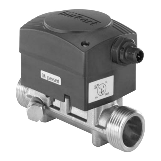
    5.1. secteur d'application (débit nominal 6 m /h soit 100 l/min) Le transmetteur de débit à ultrasons type 8081 est destiné à la mesure du débit d'eau, pouvant être légèrement chargée. 5.2.2. élément et principe de mesure Le débitmètre 8081 utilise la méthode de temps de transit. Celle-ci 5.2.
  • Page 53: Description De L'étiquette D'identification

    Type 8081 Description Le module électronique délivre ensuite un signal impulsionnel pro- Grandeur mesurée, type de débitmètre portionnel au volume ou un signal normalisé 4-20mA, proportionnel Tension d'alimentation au débit ou à la température. Principe de mesure Débit nominal 5.3.
  • Page 54: Références De Commande

    Type 8081 Description 5.4. références de commande Impulsion, NPN 559866 Fileté G 1'' Impulsion, NPN 560131 Impulsion, PNP + 559869 Fileté G 3/4'' 4-20 mA, source 0,16 à Impulsion, PNP + 2,5 20 560113 82 l/min 4-20 mA, source 0,06 à...
  • Page 55: Caractéristiques Techniques

    Type 8081 Caractéristiquestechniques caracTérisTiques Techniques 6.1. conditions d'utilisation Température ambiante : 5 à +55 °C Température de stockage : 5 à +55 °C Impulsion, NPN 560132 Humidité de l'air : < 80%, non condensée Fileté G 1 1/4'' Indice de protection : IP65 avec connecteur femelle enfiché...
  • Page 56: Caractéristiques Techniques Générales

    Type 8081 Caractéristiquestechniques 6.3. caractéristiques techniques dimensions [mm] générales 6.3.1. caractéristiques mécaniques élément matériau Boîtier, couvercle Joint en contact avec Silicone l'environnement Connecteur M12 Laiton Raccord Tube de mesure Joint en contact avec EPDM, FKM le fluide G ou NPT 3/4''...
  • Page 57: Caractéristiques Générales

    Type 8081 Caractéristiquestechniques 6.3.2. caractéristiques générales précision de la mesure Ecart de mesure max DN15 Diamètre des conduites DN15 à DN25 max DN20 maximum en % max DN25 Type du fluide Eau (liquides neutres sur demande) Température du fluide 5 à 90 °C...
  • Page 58: Caractéristiques Électriques

    Type 8081 Caractéristiquestechniques 6.3.3. caractéristiques électriques Protection contre : l'inversion de polarité Tension d'alimenta- les pics de tension tion (V+) 12-36 VDC les courts-circuits oui, pour la sortie impulsion Consommation en • Consommation propre : < 4 mA Sortie courant 4-20 mA (mode source par défaut ;...
  • Page 59: Installation Et Câblage

    • Utiliser des câbles ayant une température limite de fonctionnement Le transmetteur de débit à ultrasons 8081 peut être installé sur une adaptée à votre application. conduite horizontale ou verticale.
  • Page 60 Type 8081 Installationetcâblage Des distances amont et aval minimales ne sont pas nécessaires. En montage horizontal, Le 8081 fonctionne correctement lorsque la canalisation est remplie la température du fluide Incorrect et exempte de bulles d'air à proximité du transmetteur. En présence Correct max.
  • Page 61: Câblage Électrique

    électriques. L’alimentation doit être filtrée et régulée. → Assurer l’équipotentialité de l’installation (alimentation - 8081) : → Raccorder les différentes terres de l’installation les unes aux autres afin de supprimer les différences de potentiel pouvant se créer entre deux terres.
  • Page 62: Assembler Le Connecteur Femelle M12 (Référence De Commande 438680)

    Type 8081 Installationetcâblage 7.3.1. assembler le connecteur femelle 7.3.2. câblage de l'embase m12 mâle m12 (référence de commande → Dévisser le capuchon de protection de l'embase 438680) Non connecté 4-20 mA → 0 VDC 0 VDC Dévisser complètement le bornier [1] →...
  • Page 63: Raccordement De La Sortie Impulsion

    Type 8081 Installationetcâblage 7.3.3. raccordement de la sortie 7.3.4. raccordement de la sortie courant impulsion seule La sortie impulsion se raccorde en mode NPN (par défaut sur une La sortie courant, si elle existe, se raccorde en mode source (par version sans sortie courant) ou en mode PNP (par défaut sur une...
  • Page 64: Raccordement De La Sortie Courant Et De La Sortie Impulsion

    Type 8081 Miseenservice 7.3.5. raccordement de la sortie courant mise en service et de la sortie impulsion 8.1. consignes de sécurité Charge Charge averTissemenT risque de blessure dû à une mise en service non conforme. La mise en service non conforme peut entraîner des blessures et blanc blanc endommager l'appareil et son environnement.
  • Page 65: Réglage Et Fonctionnalités

    • Sortie courant : La sortie courant, si elle existe, est pré-programmée sur la plage de courant correspondant à la plage de débit du modèle 8081 sélec- tionné (QN0,6 ; QN1,5 ; QN 2,5 ; QN 3,5 ou QN6). français...
  • Page 66: 10.2. Entretien

    Type 8081 Stockage 10.2. entretien sTockage Le débitmètre 8081 peut être nettoyé à l‘eau ou avec un produit remarque compatible avec les matériaux qui le composent. un mauvais stockage peut endommager l'appareil. Votre fournisseur Bürkert reste à votre entière disposition pour tous renseignements complémentaires. • Stocker l'appareil dans un endroit sec et à l'abri de la poussière.
  • Page 68 www.burkert.com...

Table des Matières