elco R3400 Notice D'installation Et D'emploi

Table des Matières

Publicité

Les langues disponibles
  • FR

Les langues disponibles

Liens rapides

R3400/R3500/R3600
Operation and Installation manual
for authorized technicians only
Betriebsanleitung
für die autorisierte Fachkraft
Bedienings- en Installatiehandleiding
alleen voor bevoegde vakmensen
Notice d'installation et d'emploi
réservée à l'usage des techniciens agréés
Istruzioni per l'uso
solo per il tecnico autorizzato
05/2014
420010582400

Publicité

Table des Matières
loading

Sommaire des Matières pour elco R3400

  • Page 1 R3400/R3500/R3600 Operation and Installation manual for authorized technicians only Betriebsanleitung für die autorisierte Fachkraft Bedienings- en Installatiehandleiding alleen voor bevoegde vakmensen Notice d’installation et d’emploi réservée à l’usage des techniciens agréés Istruzioni per l'uso solo per il tecnico autorizzato 05/2014...
  • Page 3 Operation and Installation manual for authorized technicians only R3400/R3500/R3600 05/2014 420010582400...
  • Page 4: Table Des Matières

    Contents Contents ........................2 Safety General regulation .................... 3 Application ......................3 Norms and regulations ..................3 Construction Layout of boiler ....................4 Operating principle ................... 4 Technical data ......................... 5 Extent of delivery Standard boiler ....................15 Accessories ....................
  • Page 5: Safety General Regulation

    Safety General regulations Application Norms and regulations General regulations The R3400/R3500/R3600 boiler is CE  EN 61000-3-2 This documentation contains important approved and applies to the follow- Electromagnetic compatibility (EMC) - information, which is a base for safe ing European standards:...
  • Page 6: Operating Principle

    34 3rd Heat exchanger (only R3600) Flue gasses Condensate Operating principle The R3400/R3500/R3600 is a fully the boiler and leave at the back side The KM628 control unit can control the modulating boiler. The control unit of into the chimney connection.
  • Page 7: Technical Data

    Technical data Technical data R3401 - R3405 R3401 R3402 R3403 R3404 R3405 Nominal heat output at 80-60ºC max/min 656/164 733/183 857/213 971/242 1084/270 Nominal heat output at 75-60ºC max/min 657/164 734/183 858/213 972/242 1085/270 Nominal heat output at 40/30ºC max/min 663/181 741/202 867/236...
  • Page 8 Technical data Technical R3406 - R3410 R3406 R3407 R3408 R3409 R3410 Nominal heat output at 80-60ºC max/min 1196/298 1309/326 1496/373 1683/419 1870/466 Nominal heat output at 75-60ºC max/min 1197/298 1310/326 1498/373 1685/419 1872/466 Nominal heat output at 40/30ºC max/min 1209/329 1323/360 1512/412 1701/463...
  • Page 9: Dimensions

    Technical data Dimensions R3401 - R3406 Dimensions R3401 R3402 R3403 R3404 R3405 R3406 2265 2265 2653 2653 2658 2658 1166 1166 1166 1166 1355 1355 1355 1355 1355 1355 1125 1125 1570 1420 1155 1377 1330 1330 1130 1130 1330 1330 1160 1210...
  • Page 10 Technical data Dimensions R3407 - R3410 R3407 - R3408 R3409 - R3410 Dimensions R3407 R3408 R3409 R3410 2755 3265 3265 3265 1120 1630 1630 1630 1530 1330 1530 1530 1407 1207 1357 1407 126.5 126.5 176.5 126.5 1406 1206 1406 1406 1140 1140...
  • Page 11 Technical data Technical data R3501 - R3505 R3501 R3502 R3503 R3504 R3505 Nominal heat output at 80-60ºC max/min 613/175 717/204 811/231 906/258 1000/285 Nominal heat output at 75-60ºC max/min 613/175 717/204 812/231 907/258 1001/285 Nominal heat output at 40/30ºC max/min 624/195 730/228 826/258...
  • Page 12 Technical data Dimensions R3501 - R3505 Dimensions R3501 R3502 R3503 R3504 R3505 2265 2653 2653 2658 2658 1166 1166 1166 1166 1355 1355 1355 1355 1355 1125 1400 1400 1155 1155 1330 1130 1130 1330 1330 1210 1003 1053 1203 1253 1146 1146...
  • Page 13 Technical data Technical data R3600 - R3605 Standard R3600 R3601 R3602 R3603 R3604 R3605 Nominal heat output at 80-60ºC max/min 572/142 639/182 747/212 846/241 945/269 1043/297 Nominal heat output at 75-60ºC max/min 576/144 643/184 753/215 852/243 952/272 1050/300 Nominal heat output at 40/30ºC max/min 602/159 672/203 786/237...
  • Page 14 Technical data Dimensions R3600 - R3605 Standard Dimensions R3600 R3601 R3602 R3603 R3604 R3605 1958 2265 2653 2653 2658 2658 1166 1166 1166 1166 1355 1405 1405 1405 1405 1405 1175 1450 1450 1205 1427 1230 1330 1130 1130 1330 1330 1110 1210...
  • Page 15 Technical data Technical data R3600 - R3605 Split system R3600 R3601 R3602 R3603 R3604 R3605 Nominal heat output at 80-60ºC max/min 572/142 639/182 747/212 846/241 945/269 1043/297 Nominal heat output at 75-60ºC max/min 576/144 643/184 753/215 852/243 952/272 1050/300 Nominal heat output at 40/30ºC max/min 602/159 672/203 786/237...
  • Page 16 Technical data Dimensions R3600 - R3605 Split system Dimensions R3600 R3601 R3602 R3603 R3604 R3605 1958 2070 2443 2443 2443 2443 1166 1166 1166 1166 1355 1405 1405 1405 1405 1405 1230 1330 1130 1130 1330 1330 1110 1210 1003 1053 1203 1253...
  • Page 17: Extent Of Delivery

    A boiler delivery package contains the following components: Component Pcs. Package R3400/R3500/R3600 Boiler fully assembled and tested Mounted on wooden blocks with wooden border, sealed in PE foil Adjustable feet Cardboard box on top of boiler (on R3407-R3410 already fitted to boiler)
  • Page 18: Transport

    Installation Transport Boiler transport The R3400/R3500/R3600 boiler will be supplied as a complete unit being fully assembled and pre-tested. The boiler can be transported with a pallet truck (at least 1m wide), picking the boiler up from the side. Whenever necessary, the boiler can be dismantled into smaller parts for easier transport inside the building.
  • Page 19 Installation Transport Component R3407 R3408 R3409 R3410 Burner m [kg] L [mm] 1510 2050 2050 2050 B [mm] 1400 1250 1350 1450 H [mm] Heat exchanger m [kg] L [mm] 1510 2050 2050 2050 B [mm] 1425 1250 1350 1450 H [mm] Heat exchanger m [kg]...
  • Page 20: Removing The Casing

    Installation Removing the casing Boiler transport Remove the casing before transporting the boiler, in order to avoid damage to the casing parts during transportation. Removing the casing is done as fol- lows:...
  • Page 21: Boiler Installation

    Installation Boiler installation Boiler installation The boiler should be positioned in a frost-proof boiler room. If the boiler room is on the roof, the boiler itself may never be the highest point of the instal- lation. When positioning the boiler, please 1000 note the recommended minimum clea- rance in the picture.
  • Page 22: Connecting The Boiler

    Installation Connecting the boiler Connecting the boiler This chapter will explain how to make all connections to the boiler with regard  Hydraulic connections (1, 3)  Condensate drain connection (7)  Gas connection (6)  Flue gas connection (5) ...
  • Page 23 Installation Connecting the boiler Gas connection (6)  It’s recommended to use stainless The gas connection must be made by steel systems an authorized installer in accordance  The diameter of the flue gas system with the applicable national and local must be chosen by calculation ac- standards and regulations.
  • Page 24: Water And Hydraulic System

    VDI2035 standard. In the table you can find the nominal va- lues for filling and additional water for the R3400/R3500/R3600 according to the the VDI2035. The table at the left gives an indication Concentrate...
  • Page 25: Gas Supply

    Commissioning Gas supply Condensate connection Flue and air intake connections Gas supply Check the gas supply connection to the boiler for tightness. If any leakage is found, reseal the leakage before star- ting the boiler! Remove any air between the gas valve and the gas line.
  • Page 26: Prepare Boiler For First Startup

    Commissioning Prepare boiler for first startup Prepare boiler for first startup  Open gas connection;  Switch on mains isolator switch for power supply to the boiler;  Switch on boiler with on/off switch (1)  Make sure the boiler remains in standby operation use rotational switch (3);...
  • Page 27: Combustion Analysis

    Commissioning Combustion analysis Pilot burner Combustion check at full load Combustion settings Start the boiler at service mode for full for natural gas G20 / G25 load operation ( ). When you have All boilers reduced P9 to 50% (see previous chapter), the boiler will operate at 50% 10.0 ±...
  • Page 28: Air Pressure Switch

    Commissioning Air pressure switch Adjustment Air pressure switch Connect a pressure gauge to the indi- cated measuring points on the switch (1). Start the boiler at service mode for minimum load operation (W1). Measure the pressure differential across the switch, this should be ≈ 0.8 mbar. Turn the dial on the switch (2) counter- clockwise until the end.
  • Page 29: Check Water Flow

    Commissioning Check water flow Check water flow The water flow through the boiler can be checked with two different methods shown below. ∆T measurement Check the temperature difference over the boiler (∆T flow-return) when the boiler is running on 100% load. The nominal ∆T is 20K and must be at least between 15K and 25K for secure boiler operation.
  • Page 30: Check Functionality Of Safety Devices

    Commissioning Check functionality of safety devices Gas tightness check Boiler shut down Check functionality of safety devices Ionisation electrode (6) All safety devices have to be checked Remove electrical connection from the on good functioning. Safety devices on ionisation electrode while the boiler is a standard boiler are a water flow tem- running, the boiler will go in lockout perature sensor, water flow switch,...
  • Page 31: Commissioning Protocol

    Commissioning Commissioning protocol Commissioning Protocol R3400/R3500/R3600 Project Boiler type Project Serial number Address Year City Nominal load (Hi) [kW] Date Nominal output (Hi) [kW] Engineer System  Water pressure [bar] Installati- Roof top Water pH Ground floor  Water hardness [dºH]...
  • Page 32: Operating Instructions Main Menu (Operating Mode)

    Operating instructions Main menu (operating mode) Parameter menu (information/programming mode) Changing parameter values The boiler controller has two menus: the main menu (operating mode) when the lid is closed, and the parameter menu (information/programming mode) when the lid is open. Both menus and possibilities are explained in the next paragraphs. Main menu (operating mode) lid closed With the lid closed and by using the rotational switch (1) clockwise or anticlockwise the boilers’...
  • Page 33: Replacing The Electrodes

    Maintenance Checklist Replacing the electrodes Maintenance of the boiler should be Checklist carried out by authorized personnel The following activities must be carried only. out, see following paragraphs for an extensive description of the main activi- In order to ensure continued good and ties: safe operation of the boiler, it should be inspected at least once per year.
  • Page 34: Cleaning The Condensate Receptacle

    Maintenance Cleaning the condensate receptacle Cleaning and refilling the syphon Cleaning the condensate receptacle  Remove the inspection hatch (2) to access the inside of the condensate receptacle;  Clean the receptacle;  Mount the inspection hatch. Water pressure and quality Check if the water pressure and quality meet the requirements.
  • Page 35: Safety Devices

    Maintenance Maintenance Protocol Maintenance Protocol R3400/R3500/R3600 Project Boiler type Project Serial number Address Year City Nominal load (Hi) [kW] Date Nominal output (Hi) [kW] Engineer System Water pressure [bar] Water pH Water hardness [dºH] Water chloride [mg/l] Water ∆T full load [ºC]...
  • Page 36: Lockouts

    Lockouts In case of a lockout, a warning triangle (E) and a flashing error code appears on the display. The cause of a fault should first be determined and eliminated before the boiler is being reset. In case the lockout appears more than twice within 6 minutes or maintains for longer than 6 minutes, the error code is added with a “...
  • Page 37 Lockouts No. Error type Explanation Possible solution Lockout Error gas valve V1, flame ionisation signal detec- Check closing position of valve V1 within gas combi ted longer than 5 seconds after burner stop. valve, replace gas valve. Lockout Error gas valve V2, flame ionisation signal detec- Check closing position of valve V2 within gas combi ted longer than 5 seconds after burner stop.
  • Page 38: Sensor Values

    Sensor values The diagrams show the sensor values Water flow and fluegas temperature sensor (5kΩ NTC) for all boiler sensors and optional sen- sors available in accessory kits. The diagrams contain average values, as all sensors are liable to tolerances. When measuring the resistance values, the boiler should always be switched off.
  • Page 39: Declaration Of Conformity

    Declaration of Conformity Declaration of Conformity Rendamax BV, Hamstraat 76, 6465 AG Kerkrade (NL), declares that the products R3400/3500/3600 are in conformity with the following standards: EN 656 EN 15417 EN 13836 EN 55014-1 / -2 EN 61000-3-2 /-3 EN 60 335-1/ -2...
  • Page 41 Betriebsanleitung für die autorisierte Fachkraft R3400/R3500/R3600 05/2014 420010582400...
  • Page 42 Inhalt Inhalt ......................... 2 Sicherheitsbestimmungen Allgemeine Bestimmungen ................3 Verwendungszweck ..................3 Normen und Vorschriften ................. 3 Konstruktion Produktbeschreibung ..................4 Funktionsbeschreibung ..................4 Technische Daten ......................... 5 Lieferumfang Standard Ausführung ..................15 Zubehör ......................15 Installation Transport ......................16 Demontage Verkleidung .................
  • Page 43: Sicherheitsbestimmungen Allgemeine Bestimmungen

    Hinweise bezüglich Sicherheit und Zu- den europäischen Normen: verlässigkeit von Installation, Inbetrieb-  Deutschland: 92 / 42 / EEC (Wirkungsgrade von nahme und Betreibung des R3400/  RAL - UZ 61 / DIN 4702-8 Warmwasserheizungsanlagen) R3500/R3600 Kessels. Alle beschrie- ...
  • Page 44: Funktionsbeschreibung

    33 Kesselkreispumpe 34 3. Wärmetauscher (nur R3600 Rei- Luft Abgas Kondensat Funktionsbeschreibung Mit dem Feuerungsmanager KM628 Der R3400/R3500/R3600 ist ein modu- und auf der Rückseite in den Kaminan- können folgende Regelungsvarianten lierender Brennwertheizkessel. Der schluss geführt. Der Rücklaufanschluss realisiert werden: ...
  • Page 45: Technische Daten

    Technische Daten Technische Daten R3401 - R3405 R3401 R3402 R3403 R3404 R3405 Nennwärmeleistung 80-60ºC max/min 656/164 733/183 857/213 971/242 1084/270 Nennwärmeleistung 75-60ºC max/min 657/164 734/183 858/213 972/242 1085/270 Nennwärmeleistung 40/30ºC max/min 663/181 741/202 867/236 981/268 1095/298 Feuerungswärmeleistung max/min 702/176 784/196 917/229 1038/260 1159/290...
  • Page 46 Technische Daten Technische Daten R3406 - R3410 R3600 R3601 R3602 R3603 R3604 R3605 /142 Nennwärmeleistung 80-60ºC m 747/ 846/2 945/26 ax/min 643/184 53/215 2/243 576/144 1043/297 Nennwärmeleistung 75-60 /272 ºC max/m 1050/300 672/ 786/2 890/26 Nennwärmeleistung 4 istung m x/min 585/146 53/187 4/218...
  • Page 47 Technische Daten Abmessungen R3401 - R3406 Abmessung R3401 R3402 R3403 R3404 R3405 R3406 2265 2265 2653 2653 2658 2658 1166 1166 1166 1166 1355 1355 1355 1355 1355 1355 1125 1125 1570 1420 1155 1377 1330 1330 1130 1130 1330 1330 1160 1210...
  • Page 48 Technische Daten Abmessungen R3407 - R3410 R3407 - R3408 R3409 - R3410 Abmessung R3407 R3408 R3409 R3410 2755 3265 3265 3265 1120 1630 1630 1630 1530 1330 1530 1530 1407 1207 1357 1407 126.5 126.5 176.5 126.5 1406 1206 1406 1406 1140 1140...
  • Page 49 Technische Daten Technische Daten R3501 - R3505 R3501 R3502 R3503 R3504 R3505 Nennwärmeleistung 80-60ºC max/min 613/175 717/204 811/231 906/258 1000/285 Nennwärmeleistung 75-60ºC max/min 613/175 717/204 812/231 907/258 1001/285 Nennwärmeleistung 40/30ºC max/min 624/195 730/228 826/258 923/288 1018/319 Feuerungswärmeleistung max/min 653/187 764/218 865/247 966/276 1066/305...
  • Page 50 Technische Daten Abmessungen R3501 - R3505 Abmessung R3501 R3502 R3503 R3504 R3505 2265 2653 2653 2658 2658 1166 1166 1166 1166 1355 1355 1355 1355 1355 1125 1400 1400 1155 1155 1330 1130 1130 1330 1330 1210 1003 1053 1203 1253 1146 1146...
  • Page 51 Technische Daten Technische Daten R3600 - R3605 Standard R3600 R3601 R3602 R3603 R3604 R3605 Nennwärmeleistung 80-60ºC max/min 572/142 639/182 747/212 846/241 945/269 1043/297 Nennwärmeleistung 75-60ºC max/min 576/144 643/184 753/215 852/243 952/272 1050/300 Nennwärmeleistung 40/30ºC max/min 602/159 672/203 786/237 890/268 994/300 1097/331 Feuerungswärmeleistung max/min 585/146...
  • Page 52 Technische Daten Abmessungen R3600 - R3605 Standard Abmessung R3600 R3601 R3602 R3603 R3604 R3605 1958 2265 2653 2653 2658 2658 1166 1166 1166 1166 1355 1405 1405 1405 1405 1405 1175 1450 1450 1205 1427 1230 1330 1130 1130 1330 1330 1110 1210...
  • Page 53 Technische Daten Technische Daten R3600 - R3605 Split system R3600 R3601 R3602 R3603 R3604 R3605 Nennwärmeleistung 80-60ºC max/min 572/142 639/182 747/212 846/241 945/269 1043/297 Nennwärmeleistung 75-60ºC max/min 576/144 643/184 753/215 852/243 952/272 1050/300 Nennwärmeleistung 40/30ºC max/min 602/159 672/203 786/237 890/268 994/300 1097/331 Feuerungswärmeleistung max/min...
  • Page 54 Technische Daten Abmessungen R3600 - R3605 Split system Abmessung R3600 R3601 R3602 R3603 R3604 R3605 1958 2070 2443 2443 2443 2443 1166 1166 1166 1166 1355 1405 1405 1405 1405 1405 1230 1330 1130 1130 1330 1330 1110 1210 1003 1053 1203 1253...
  • Page 55: Lieferumfang

    Lieferumfang Standardausführung Zubehör Standard Ausführung Der Lieferumfang eines Heizkessels enthält die folgenden Komponenten: Komponenten Verpackungsart Heizkessel vollständig montiert und geprüft Auf Holzpalette mit Holzrahmen, eingewickelt in PE Folie Höhenverstellbare Füße In separatem Karton auf dem Kessel (auf R3407-R3410 bereits am Kessel montiert) Siphon für Kondensatanschluss In separatem Karton auf dem Kessel Bedienungs- und Installationsanleitung...
  • Page 56 Installation Kesseltransport Kesseltransport Der R3400/R3500/R3600 ist ein voll- ausgerüstetes Kompaktheizgerät, wel- ches voreingestellt und geprüft ist. Der Heizkessel kann seitwärts mit ei- nem Hubstapler aufgeladen und trans- portiert werden. Wo notwendig, kann der Heizkessel in kleinere Teile zerlegt werden um einen einfacheren Transport in das Gebäude...
  • Page 57: Transport

    Installation Transport Komponente R3407 R3408 R3409 R3410 Brenner m [kg] L [mm] 1510 2050 2050 2050 B [mm] 1400 1250 1350 1450 H [mm] 1. Wärmetauscher m [kg] L [mm] 1510 2050 2050 2050 B [mm] 1425 1250 1350 1450 H [mm] 2.
  • Page 58: Demontage Verkleidung

    Installation Demontage Verkleidung Vor Transport des Kessels die Ab- deckungen demontieren um Beschädi- gungen der Kesselverkleidung zu vermeiden. Die Demontage der Abdeckungen er- folgt wie auf den Fotos dargestellt:...
  • Page 59: Anschlüsse

    Installation Aufstellung Installation Der Kessel sollte in einem frostschutz- sicheren Raum aufgestellt werden. Wird der Kessel im Dachboden aufge- stellt, darf dieser nicht der höchste Punkt der Installation sein. Bitte beachten Sie die empfohlenen 1000 Abstände gemäss nebenstehender Skizze beim Aufstellen des Kessels. Bei kleineren Abständen werden die Wartungsarbeiten erschwert.
  • Page 60 (Europäische, Nationale und Lokale) entspricht. Es obliegt der installieren- den Fachkraft dass diese Normen und Vorschriften eingehalten werden. Hydraulische Anschlüsse Der R3400/R3500/R3600 muss so in das System eingebunden werden, dass eine dauerhafte Wasserzirkulation (Zwangsumlauf-prinzip) zu jeder Zeit gewährleistet ist. Schließe den Vorlauf (3) und den Rück- lauf (1) vom System leckfrei an die entsprechenden Kesselanschlüsse an.
  • Page 61 Installation Kesselanschlüsse Gas Anschluss (6) Beachten sie folgende Empfehlungen: Der Gasanschluss erfolgt durch eine  Verwenden sie nur korrosionsbestän- ausgewiesene Fachkraft. Auch hier diges Material gelten die nationalen und lokalen  Der Durchmesser muss berechnet Normen und Vorschriften. und gemäß den nationalen Vorschrif- ten ausgewählt werden Schließe die Gasleitung leckfrei an den ...
  • Page 62: Wasser- Und Hydrauliksystem

    Mengen mit entsprechender Härte gemäß der deutschen Norm VDI2035 zu beachten. In nebenstehender Tabelle sind die Nennwerte für die Befüllung und zu- sätzliches Wasser für den R3400/ R3500/R3600 gemäß der VDI2035 angegeben. Konzentrat Kapazität der Anlage Q (kW)
  • Page 63: Gasversorgung

    Inbetriebnahme Gasversorgung Kondensatanschluss Abgas- und Zuluftanschlüsse Gasversorgung Prüfen Sie den Anschluss zur Gasver- sorgung zum Kessel auf Dichtheit. Evtl. Lecks sind abzudichten, bevor der Kes- sel gestartet wird. Entlüften Sie Gasleitung und Gasventil. Dies erfolgt an der Messstelle (1) am Gasdruckwächter.
  • Page 64: Vorbereitung Für 1. Inbetriebnahme

    Inbetriebnahme Vorbereitung für 1. Inbetriebnahme Vorbereitung für 1. Inbetriebnahme  Öffnen Sie den Gasanschluss;  Betätigen Sie den Netztrennschalter, um den Kessel mit Strom zu versor- gen;  Schalten Sie den Kessel mit dem Ein- /Ausschalter (1) ein;  Stellen Sie sicher, dass der Kessel im Standby-Betrieb (K) (2) bleibt, betäti- gen Sie den Drehschalter (3);...
  • Page 65: Verbrennungswerte

    Inbetriebnahme Verbrennungswerte Zündbrenner Verbrennungswerte bei Volllast Verbrennungseinstellungen für Starten Sie den Kessel im Wartungsbe- Erdgas G20 / G25 trieb unter Volllast (W2). Wenn Sie den Alle ketels P9 auf 50 % gesenkt haben (siehe vor- gehendes Kapitel), arbeitet der Kessel 10.0 ±...
  • Page 66: Luftdruckwächter

    Inbetriebnahme Luftdruckwächter Einstellung Luftdruckwächter Schliessen sie ein Differenzdruck- Messgerät an auf die Messstellen des Wächters (1). Schalten Sie den Kessel in Wartungsbetrieb unter Mindestlast (W1). Messen Sie den Differenzdruck über den Wächter, dieser soll ≈ 0.8 mbar sein. Drehen Sie den Knopf am Wächter (2) gegen den Uhrzeigersinn bis zum Ende.
  • Page 67: Wasserdurchsatz Prüfen

    Inbetriebnahme Prüfung Wasserdurchsatz Wasserdurchsatz prüfen Der Wasserdurchsatz durch den Kessel kann über zwei verschiedene Metho- den geprüft werden: ∆T-Messung Prüfen Sie die Temperaturdifferenz = (∆T / ∆T ) * q tatsächlich Nenn Gemess Nenn über dem Kessel (∆T Vorlauf-Rücklauf), wenn der Kessel unter Volllast arbeitet. Die Nenn-∆T entspricht 20 K und muss für einen sicheren Kesselbetrieb minde- stens zwischen 15 K und 25 K liegen.
  • Page 68: Sicherheitseinrichtungen Prüfen

    Inbetriebnahme Funktion der Sicherheitseinrichtungen prüfen Gasdichtheitsprüfung Kessel außer Betrieb setzen Funktion der Sicherheitseinrichtun- Ionisationselektrode (6) gen prüfen Entfernen Sie die elektrische Steckver- Alle Sicherheitseinrichtungen sind auf bindung von der Ionisationselektrode, korrekte Funktion zu prüfen. Zu den während der Kessel läuft. Der Kessel Sicherheitseinrichtungen an Standard- schaltet ab (Nr.
  • Page 69: Inbetriebnahme Protokoll

    Inbetriebnahme Inbetriebnahme-Protokoll Inbetriebnahme-Protokoll R3400/R3500/R3600 Projekt Kesseltyp Projekt Seriennummer Adresse Jahr Nennwärmebelastung (Hi) [kW] Datum Nennwärmeleistung (Hi) [kW] Ingenieur System Wasserdruck [bar] Anlage: Dachgeschoss  Wasser pH Erdgeschoss  Wasserhärte [dºH] Keller   Wasserchlorid [mg/l] Andere: ......Wasser-∆T Volllast [ºC]...
  • Page 70: Bedienungs-/Parametereinstellungen

    Bedienungs- und Parametereinstellungen Hauptmenü (Bedienungsmenü) Parametermenü (Information/Programmier Menü) Parametereinstellungen verändern Der Feuerungsmanager hat zwei Menüs: das Hauptmenü (Bedienungsmenü) [bei geschlossenem Deckel], und das Parame- ter Menü (Information/Programmier Menü) [bei offenem Deckel]. Beide Menü - Einstellungsmöglichkeiten sind auf den näch- sten Seiten aufgeführt. Hauptmenü...
  • Page 71: Ersetzen Der Elektroden

    Wartung Checkliste Ersetzen der Elektroden Der Kessel darf nur von befugtem Per- Checkliste  Prüfung des Wasserdurchsatzes sonal gewartet werden. Folgenden Maßnahmen sind durchzu- durch den Kessel; führen:  Prüfung/Korrektur der Verbrennungs- Um den korrekten und sicheren Betrieb werte bei Volllast und Mindestlast mit des Kessels sicherzustellen, sollte die- ...
  • Page 72: Reinigung Der Kondensatwanne

    Wartung Reinigung der Kondensatwanne Reinigen und Auffüllen des Siphons Reinigung der Kondensatwanne  Etfernen Sie den Deckel (2) an der Kondensatwanne;  Reinigen Sie die Wanne (1);  Montieren Sie den Deckel wieder zurück. Verbrennungswerte Wasserdurchsatz Prüfen Sie den Verbrennungsvorgang Prüfen Sie, ob der Wasserdurchsatz unter Volllast und Mindestlast und korri- durch den Kessel innerhalb der Grenz-...
  • Page 73: Wartungsprotokoll

    Wartung Wartungs-Protokoll Wartungs-Protokoll R3400/R3500/R3600 Projekt Kesseltyp Projekt Seriennummer Adresse Jahr Nennwärmebelastung (Hi) [kW] Datum Nennwärmeleistung (Hi) [kW] Ingenieur System Wasserdruck [bar] Anlage: Dachgeschoss  Wasser pH Erdgeschoss  Wasserhärte [dºH] Keller   Wasserchlorid [mg/l] Andere: ......Wasser-∆T Volllast [ºC]...
  • Page 74: Störungen

    Störungen Im Falle einer Abschaltung erscheint ein Warnzeichen (E) und ein blinkender Fehlercode auf dem Display. Die Störungsursa- che muss behoben werden, bevor man den Kessel R600 zurücksetzen kann. Im Fall, dass die Abschaltung mehr als 2 x in- nerhalb von 6 Minuten erscheint oder länger als 6 Minuten ansteht, wird dem Fehlercode das Zeichen “ ”...
  • Page 75 Störungen Nr. Fehler Beschreibung des Fehlers Mögliche Lösung Verriegelnd Fehler Gasventil V1, Flammenionisationssignal Prüfen Sie die Schließposition von Ventil V1 innerhalb für mehr als 5 Sekunden nach Brennerstopp des Kombi-Gasventils, ersetze Gasventil. erkannt. Verriegelnd Fehler Gasventil V2, Flammenionisationssignal Prüfen Sie die Schließposition von Ventil V2 innerhalb für mehr als 5 Sekunden nach Brennerstopp des Kombi-Gasventils, ersetze Gasventil.
  • Page 76: Fühlerkennwerte

    Fühlerkennwerte In den nebenstehenden Diagrammen Vorlauftemperatur– und Abgastemperaturfühler (5kΩ NTC) sind die Sensorwerte für alle Kes- selsensoren und in den Zubehörsätzen enthaltenen, optionalen Sensoren an- gegeben. Die Diagramme zeigen Durchschnittswerte, da alle Sensoren Schwankungen unterliegen. Bei der Messung der Widerstandswerte sollte der Kessel immer abgeschaltet sein.
  • Page 77: Konformitätserklärung

    Konformitätserklärung Konformitätserklärung Rendamax BV, Hamstraat 76, 6465 AG Kerkrade (NL), erklärt, dass die Produkte R3400/3500/3600 mit folgenden Normen übereinstimmen: EN 656 EN 15417 EN 13836 EN 55014-1 / -2 EN 61000-3-2 /-3 EN 60 335-1/ -2 Gemäß den Bestimmungen der Richtlinien:...
  • Page 79 Bedienings- en Installatiehandleiding Alleen voor bevoegde vakmensen R3400/R3500/R3600 05/2014 420010582400...
  • Page 80 Inhoud Inhoud ......................... 2 Veiligheid Algemene bepalingen ..................3 Toepassing ....................... 3 Normen en voorschriften .................. 3 Constructie Opbouw van het toestel ..................4 Werkingsprincipe ....................4 Technische gegevens ......................... 5 Leveromvang Standaard toestel ................... 15 Accessoires ....................15 Installatie Transport ......................
  • Page 81: Veiligheid Algemene Bepalingen

    Veiligheid Algemene bepalingen Toepassing Normen en voorschriften Algemene bepalingen De R3400/R3500/R3600 is CE ge- Deze documentatie bevat informatie, keurd volgens de volgende Europe-  EN 60335-1 die dient als basis voor een veilige en se regelgevingen: Household and similar electrical appli-...
  • Page 82: Werkingsprincipe

    R3600) A lucht B gas C rookgassen D condensaat Werkingsprincipe De KM628 regelunit controleert het De R3400/R3500/R3600 is een trap- warmtewsisselaar getransporteerd, toestel tijdens bedrijf via: loos modulerend verwarmingstoestel. waarna deze het toestel aan de achter-  Constante aanvoertemperatuur De regelunit in het toestel past de mo- zijde verlaten via de rookgasadapter.
  • Page 83: Technische Gegevens

    Technische gegevens Technische gegevens R3401 - R3405 R3401 R3402 R3403 R3404 R3405 Nominaal vermogen bij 80-60ºC max/min 656/164 733/183 857/213 971/242 1084/270 Nominaal vermogen bij 75-60ºC max/min 657/164 734/183 858/213 972/242 1085/270 Nominaal vermogen bij 40/30ºC max/min 663/181 741/202 867/236 981/268 1095/298 Nominale belasting Hi max/min...
  • Page 84 Technische gegevens Technische gegevens R3406 - R3410 R3406 R3407 R3408 R3409 R3410 Nominaal vermogen bij 80-60ºC max/min 1196/298 1309/326 1496/373 1683/419 1870/466 Nominaal vermogen bij 75-60ºC max/min 1197/298 1310/326 1498/373 1685/419 1872/466 Nominaal vermogen bij 40/30ºC max/min 1209/329 1323/360 1512/412 1701/463 1890/515 Nominale belasting Hi max/min...
  • Page 85 Technische gegevens Afmetingen R3401 - R3406 Afmeting R3401 R3402 R3403 R3404 R3405 R3406 2265 2265 2653 2653 2658 2658 1166 1166 1166 1166 1355 1355 1355 1355 1355 1355 1125 1125 1570 1420 1155 1377 1330 1330 1130 1130 1330 1330 1160 1210...
  • Page 86 Technische gegevens Afmetingen R3407 - R3410 R3407 - R3408 R3409 - R3410 Afmeting R3407 R3408 R3409 R3410 2755 3265 3265 3265 1120 1630 1630 1630 1530 1330 1530 1530 1407 1207 1357 1407 126.5 126.5 176.5 126.5 1406 1206 1406 1406 1140 1140...
  • Page 87 Technische gegevens Technische gegevens R3501 - R3505 R3501 R3502 R3503 R3504 R3505 Nominaal vermogen bij 80-60ºC max/min 613/175 717/204 811/231 906/258 1000/285 Nominaal vermogen bij 75-60ºC max/min 613/175 717/204 812/231 907/258 1001/285 Nominaal vermogen bij 40/30ºC max/min 624/195 730/228 826/258 923/288 1018/319 Nominale belasting Hi max/min...
  • Page 88 Technische gegevens Afmetingen R3501 - R3505 Afmeting R3501 R3502 R3503 R3504 R3505 2265 2653 2653 2658 2658 1166 1166 1166 1166 1355 1355 1355 1355 1355 1125 1400 1400 1155 1155 1330 1130 1130 1330 1330 1210 1003 1053 1203 1253 1146 1146...
  • Page 89 Technische gegevens Technische gegevens R3600 - R3605 Standard R3600 R3601 R3602 R3603 R3604 R3605 Nominaal vermogen bij 80-60ºC max/min 572/142 639/182 747/212 846/241 945/269 1043/297 Nominaal vermogen bij 75-60ºC max/min 576/144 643/184 753/215 852/243 952/272 1050/300 Nominaal vermogen bij 40/30ºC max/min 602/159 672/203 786/237...
  • Page 90 Technische gegevens Afmetingen R3600 - R3605 Standard Afmeting R3600 R3601 R3602 R3603 R3604 R3605 1958 2265 2653 2653 2658 2658 1166 1166 1166 1166 1355 1405 1405 1405 1405 1405 1175 1450 1450 1205 1427 1230 1330 1130 1130 1330 1330 1110 1210...
  • Page 91 Technische gegevens Technische gegevens R3600 - R3605 Split system R3600 R3601 R3602 R3603 R3604 R3605 Nominaal vermogen bij 80-60ºC max/min 572/142 639/182 747/212 846/241 945/269 1043/297 Nominaal vermogen bij 75-60ºC max/min 576/144 643/184 753/215 852/243 952/272 1050/300 Nominaal vermogen bij 40/30ºC max/min 602/159 672/203 786/237...
  • Page 92 Technische gegevens Afmetingen R3600 - R3605 Split system Afmeting R3600 R3601 R3602 R3603 R3604 R3605 1958 2070 2443 2443 2443 2443 1166 1166 1166 1166 1355 1405 1405 1405 1405 1405 1230 1330 1130 1130 1330 1330 1110 1210 1003 1053 1203 1253...
  • Page 93: Accessoires

    Standaard toestel Een standaard toestel bevat volgende componenten: Component Aantal Verpakking R3400/R3500/R3600 Verwarmingstoestel, compleet Gemonteerd op houten blokken inclusief houten samengebouwd en getest stootrand, gesealed in PE folie Stelvoeten In kartonnen doos, bovenop toestel (op R3407-R3410 reeds op de ketel gemonteerd)
  • Page 94: Installatie

    Installatie Transport Transport De R3400/R3500/R3600 wordt volledig samengebouwd en ingesteld geleverd. Het toestel kan met behulp van een palletwagen met vorken van minimaal 1m worden getransporteerd. De pallet- wagen kan van de zijkant onder het toestel geplaatst worden. Wanneer intern transport dit vereist,...
  • Page 95 Installatie Transport Component R3407 R3408 R3409 R3410 Brander m [kg] L [mm] 1510 2050 2050 2050 B [mm] 1400 1250 1350 1450 H [mm] warmtewisselaar m [kg] L [mm] 1510 2050 2050 2050 B [mm] 1425 1250 1350 1450 H [mm] warmtewisselaar m [kg] L [mm]...
  • Page 96: Beplating Verwijderen

    Installatie Beplating verwijderen Transport De beplating dient voor transport van het toestel verwijderd te worden om beschadigingen te voorkomen. Het verwijderen van de beplating gaat als volgt:...
  • Page 97: Opstelling

    Installatie Opstelling Opstelling Het toestel dient te worden opgesteld in een vorstvrije ruimte. In geval van een dakopstelling dient het systeem dusda- nig te worden aangelegd, dat het toe- stel niet het hoogste punt van de instal- latie is. Het toestel dient geplaatst te 1000 worden met inachtneming van voldoen- de vrije ruimte aan de verschillende...
  • Page 98: Aansluiten

    Installatie Aansluiten Aansluiten Dit hoofdstuk geeft aan hoe de volgen- de aansluitingen op een correcte ma- nier te maken:  Waterzijdige aansluitingen (1, 3)  Condensafvoer (7)  Gasaansluiting (6)  Rookgasafvoer (5)  Luchtinlaat (alleen bij gebruik als ge- sloten toestel, apart bestellen (2) ) ...
  • Page 99 Installatie Aansluiten Gasaansluiting (6)  De lengte van de rookgasafvoerbuis De gasaansluiting mag uitsluitend dient zo kort mogelijk gehouden te door gecertificeerde bedrijven worden worden (zie planningsdocumentatie aangesloten. Hierbij dienen de (inter-) voor maximale afvoerlengte) nationale en lokale normen en voor- ...
  • Page 100: Inbedrijfstelling

    VDI2035. In de tabel hier- naast zijn de nominale waarden voor (bij)vulwater te vinden voor de R3400/ R3500/R3600, gerelateerd aan de VDI2035. Concentratie Vermogen van installatie Q (kW)
  • Page 101: Gastoevoer

    Inbedrijfstelling Gastoevoer Condensafvoer Rookgasafvoer en luchtinlaat Gastoevoer Controleer de gasaansluiting naar de ketel op lekkage. Indien lekkage wordt vastgesteld, dient de aansluiting te wor- den hersteld alvorens het toestel te starten! Ontlucht de gasleiding tot aan het gas- blok. Hiervoor kan gebruik worden ge- maakt van de meetnippel (1) op de gasdrukschakelaar.
  • Page 102: Toestel Voorbereiden Voor Start

    Inbedrijfstelling Toestel voorbereiden voor start Toestel voorbereiden voor start  Open gaskraan;  Schakel hoofdschakelaar in voor voe- dingsspanning naar het toestel;  Schakel toestel in via aan/uit- schakelaar (1)  Selecteer bedrijfsmodus “standby” (2) met behulp van draaischakelaar (3); ...
  • Page 103: Verbrandingsanalyse

    Inbedrijfstelling Verbrandingsanalyse Aansteekbrander Instellen verbrandingswaarde bij Verbrandingswaarden aardgas vollast G20 / G25 Start het toestel op servicebedrijf vol- Alle ketels last (W2). Wanneer P9 is gereduceerd tot 50% (zie vorige paragraaf), zal het 10.0 ± 0.2 2, max toestel op 50% belasting blijven. Laat <...
  • Page 104: Luchtdrukschakelaar

    Inbedrijfstelling Luchtdrukschakelaar Instellen luchtdrukschakelaar Sluit de manometer aan op de aange- geven meetpunten op de luchtdruk- schakelaar (1). Start het toestel op ser- vicebedrijf minimumlast (W1). Meet ver- volgens het drukverschil over de scha- kelaar, dit dient ≈ 0.8 mbar te zijn. Draai de knop op de luchtdrukscha- kelaar (2) linksom tot het einde.
  • Page 105: Waterstroming

    (∆p aanvoer-retour) wanneer de pomp is ingeschakeld op maximaal toerental (brander hoeft niet ingeschakeld te zijn). De nominale ∆p voor elk type R3400/R3500/R3600 is te vinden in onderstaande tabel, de actuele ∆p dient zich te bevinden tussen: 0.35*∆p ≤ ∆P ≤ 1.75*∆p...
  • Page 106: Controle Van Veiligheidsrelevante Componenten

    Inbedrijfstelling Controle van veiligheidsrelevante componenten Controle op gasdichtheid Toestel uit bedrijf nemen Controle van veiligheidsrelevante Ionisatie-electrode (6) componenten Verwijder de stekker van de ionisatie- De functionaliteit van alle veiligheids- electrode terwijl het toestel in bedrijf is, relevante componenten dient te worden dit resulteert in een storing met num- gecontroleerd.
  • Page 107: Inbedrijfstellingsrapport

    Inbedrijfstelling Inbedrijfstellingsrapport Inbedrijfstellingsrapport R3400/R3500/R3600 Project Ketel type Project Serienummer Adres Bouwjaar Plaats Nominale belasting (Hi) [kW] Datum Nominaal vermogen (Hi) [kW] Technicus Systeem  Waterdruk [bar] Installatie: Dakopstelling Water pH Begane grond  Water hardheid [dºH] Kelder  Water chloridegehalte [mg/l] Anders: ......
  • Page 108: Bediening Hoofdmenu (Bedrijfsmodus)

    Bediening Hoofdmenu (bedrijfsmodus) Parameter menu (informatie/programmeer-modus) Parameters wijzigen Bediening De ingebouwde regeling heeft 2 menu’s: het hoofdmenu (bedrijfsmodus) wanneer het klepje is gesloten, en het parameter menu (informatie/programmeer-modus) wanneer het klepje is geopend. Beide menu’s worden uitgelegd in de volgende par- agrafen.
  • Page 109: Electrodes Vervangen

     Controleer/corrigeer de verbrandings- gende paragrafen voor gedetailleerde waarden op vollast en minimumlast Om goed functioneren van de R3400/ uitleg van de afzonderlijke punten: met behulp van een rookgasmeter; R3500/R3600 zeker te stellen, dient ...
  • Page 110: Condensbak Reinigen

    Onderhoud Condensbak reinigen Sifon reinigen Condensbak reinigen  Verwijder het inspectieluik (2) om toegang te krijgen tot de binnenzijde van de condensbak;  Reinig de condensbak (1);  Monteer het inspectieluik. Waterdruk en waterkwaliteit Controleer of de waterdruk en water- kwaliteit voldoen aan de gestelde ei- sen.
  • Page 111: Onderhoudsrapport

    Onderhoud Onderhoudsrapport Onderhoudsrapport R3400/R3500/R3600 Project Ketel type Project Serienummer Adres Bouwjaar Plaats Nominale belasting (Hi) [kW] Datum Nominaal vermogen (Hi) [kW] Technicus Systeem Waterdruk [bar] Water pH Water hardheid [dºH] Water chloridegehalte [mg/l] Water ∆T vollast [ºC] Water ∆p [kPa]...
  • Page 112: Storingen

    Storingen In geval van een storing wordt in het display, naast een waarschuwingsindicatie (E), een storingscode (knipperend) weerge- geven. Voordat de storing wordt gereset , dient de oorzaak gevonden en opgelost te worden. Wanneer dezelfde storing vaker dan 2 keer binnen 6 minuten optreedt of langer dan 6 minuten aanhoudt, zal de storingscode worden weergegeven met de toevoeging “...
  • Page 113 Storingen Vergrendelend Storing gasklep V1, ionisatiesignaal gedetec- Controleer sluiten van gasklep V1 in gas- teerd langer dan 5 seconden na branderstop. combiblok, vervang gasblok. Vergrendelend Storing gasklep V2, ionisatiesignaal gedetec- Controleer sluiten van gasklep V2 in gas- teerd langer dan 5 seconden na branderstop. combiblok, vervang gasblok.
  • Page 114: Weerstandswaarden Voelers

    Weerstandswaarden voelers In onderstaande grafieken zijn de weer- Aanvoervoeler en rookgasvoeler (5kΩ NTC) standswaarden weergegeven van alle voelers die worden gebruikt in het stan- daardtoestel en de leverbare optiesets. De grafieken zijn een weergave van de gemiddelde waarden, kleine afwijkin- gen als gevolg van toleranties zijn mo- gelijk.
  • Page 115: Verklaring Van Overeenstemming

    Verklaring van overeenstemming Verklaring van overeenstemming Rendamax BV, Hamstraat 76, 6465 AG Kerkrade (NL), verklaart dat de producten R3400/3500/3600 zijn geconstrueerd volgens volgende richtlijnen: EN 656 EN 15417 EN 13836 EN 55014-1 / -2 EN 61000-3-2 /-3 EN 60 335-1/ -2...
  • Page 117 Notice d’installation et d’emploi réservée à l’usage des techniciens agréés R3400/R3500/R3600 05/2014 420010582400...
  • Page 118 Sommaire Sommaire ......................... 2 Sécurité La notice ......................3 Utilisation ......................3 Normes et réglementations ................3 Construction Schéma de fonctionnement ................4 Principe de fonctionnement ................4 Caractéristiques techniques ......................... 5 Présentation de la chaudière Chaudière standard ..................15 Accessoires ....................
  • Page 119: Sécurité La Notice

    Sécurité La notice Utilisation Normes et réglementations Réglementations générales La chaudière R3400/R3500/R3600 est EN 61000-3-2 Cette notice contient des informations conforme à la Compatibilité électromagnétique norme CE et répond aux standards importantes nécessaires à une installa- (CEM) – partie 3-2: limites – limites tion sans danger et fiable, une mise en européens suivants :...
  • Page 120: Principe De Fonctionnement

    Construction Schéma de fonctionnement Principe de fonctionnement Schéma de fonctionnement La chaudière R3400/R3500/R3600 est composée des composantes principales suivantes: Raccordement eau de retour Raccordement gaz brûlés Interrupteur débit d’eau Soupape de sécurité Raccordement débit d’eau Robinet de remplissage/vidange Panneau dessus Panneau distribuant Brûleur...
  • Page 121: Caractéristiques Techniques

    Caractéristiques techniques Caractéristiques techniques R3401 - R3405 R3401 R3402 R3403 R3404 R3405 Puissance nominale utile à 80-60°C max/min 656/164 733/183 857/213 971/242 1084/270 Puissance nominale utile à 75-60°C max/min 657/164 734/183 858/213 972/242 1085/270 Puissance nominale utile à 40/30°C max/min 663/181 741/202 867/236...
  • Page 122 Caractéristiques techniques Caractéristiques techniques R3406 - R3410 R3406 R3407 R3408 R3409 R3410 Puissance nominale utile à 80-60°C max/min 1196/298 1309/326 1496/373 1683/419 1870/466 Puissance nominale utile à 75-60°C max/min 1197/298 1310/326 1498/373 1685/419 1872/466 Puissance nominale utile à 40/30°C max/min 1209/329 1323/360 1512/412...
  • Page 123 Caractéristiques techniques Dimensions R3401 - R3406 Dimensions R3401 R3402 R3403 R3404 R3405 R3406 2265 2265 2653 2653 2658 2658 1166 1166 1166 1166 1355 1355 1355 1355 1355 1355 1125 1125 1570 1420 1155 1377 1330 1330 1130 1130 1330 1330 1160 1210...
  • Page 124 Caractéristiques techniques Dimensions R3407 - R3410 R3407 - R3408 R3409 - R3410 Dimensions R3407 R3408 R3409 R3410 2755 3265 3265 3265 1120 1630 1630 1630 1530 1330 1530 1530 1407 1207 1357 1407 126.5 126.5 176.5 126.5 1406 1206 1406 1406 1140 1140...
  • Page 125 Caractéristiques techniques Caractéristiques techniques R3501 - R3505 R3501 R3502 R3503 R3504 R3505 Puissance nominale utile à 80-60°C max/min 613/175 717/204 811/231 906/258 1000/285 Puissance nominale utile à 75-60°C max/min 613/175 717/204 812/231 907/258 1001/285 Puissance nominale utile à 40/30°C max/min 624/195 730/228 826/258...
  • Page 126 Caractéristiques techniques Dimensions R3501 - R3505 Dimensions R3501 R3502 R3503 R3504 R3505 2265 2653 2653 2658 2658 1166 1166 1166 1166 1355 1355 1355 1355 1355 1125 1400 1400 1155 1155 1330 1130 1130 1330 1330 1210 1003 1053 1203 1253 1146 1146...
  • Page 127 Caractéristiques techniques Caractéristiques techniques R3600 - R3605 Standard R3600 R3601 R3602 R3603 R3604 R3605 Puissance nominale utile à 80-60°C max/min 572/142 639/182 747/212 846/241 945/269 1043/297 Puissance nominale utile à 75-60°C max/min 576/144 643/184 753/215 852/243 952/272 1050/300 Puissance nominale utile à 40/30°C max/min 602/159 672/203 786/237...
  • Page 128 Caractéristiques techniques Dimensions R3600 - R3605 Standard Dimensions R3600 R3601 R3602 R3603 R3604 R3605 1958 2265 2653 2653 2658 2658 1166 1166 1166 1166 1355 1405 1405 1405 1405 1405 1175 1450 1450 1205 1427 1230 1330 1130 1130 1330 1330 1110 1210...
  • Page 129 Caractéristiques techniques Caractéristiques techniques R3600 - R3605 Split System R3600 R3601 R3602 R3603 R3604 R3605 Puissance nominale utile à 80-60°C max/min 572/142 639/182 747/212 846/241 945/269 1043/297 Puissance nominale utile à 75-60°C max/min 576/144 643/184 753/215 852/243 952/272 1050/300 Puissance nominale utile à 40/30°C max/min 602/159 672/203 786/237...
  • Page 130 Caractéristiques techniques Dimensions R3600 - R3605 Split System Dimensions R3600 R3601 R3602 R3603 R3604 R3605 1958 2070 2443 2443 2443 2443 1166 1166 1166 1166 1355 1405 1405 1405 1405 1405 1230 1330 1130 1130 1330 1330 1110 1210 1003 1053 1203 1253...
  • Page 131: Présentation De La Chaudière

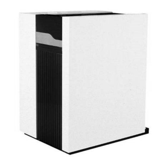
    Dans l’emballage, vous trouverez les éléments suivants : Composantes Emballage R3400/R3500/R3600 entièrement montée et testée Montée sur cales en bois avec bordure en bois, scellée dans un film PE Pieds réglables Boîte en carton sur le haut de la chaudière (sûr R3407-R3410 déjà...
  • Page 132: Transport De La Chaudière

    Installation Transport de la chaudière Transport de la chaudière La chaudière R3400/R3500/R3600 est livrée comme une unité complète, entiè- rement assemblée et soumise à des tests préalables. La chaudière peut être transportée par transpalette (longeur min 1m), entrer par le côté. Si nécessaire, la chaudière peut être démontée en...
  • Page 133: Transport

    Installation Transport Composantes R3407 R3408 R3409 R3410 Brûleur m [kg] L [mm] 1510 2050 2050 2050 B [mm] 1400 1250 1350 1450 H [mm] échangeur m [kg] L [mm] 1510 2050 2050 2050 B [mm] 1425 1250 1350 1450 H [mm] échangeur m [kg] L [mm]...
  • Page 134: Enlever Le Revêtement

    Installation Enlever le revêtement Transport de la chaudière Enlever le revêtement, avant de transporter la chaudière, afin d’éviter d’endommager les pièces de revête- ment pendant le transport. Pour enlever le revêtement, procéder de la façon suivante:...
  • Page 135: Installation De La Chaudière

    Installation Installation de la chaudière Installation de la chaudière La chaudière doit être placée dans une salle protégée contre le gel. Si la salle de chaudière est sur le toit, la chaudière ne doit jamais être le point le plus haut de l’installation. En positionnant la chaudière, veuillez 1000 tenir compte de l’espacement minimum...
  • Page 136: Raccordements

    Installation Raccordements Raccordement de la chaudière Ce chapitre explique comment faire tous les raccordements de la chaudière:  Raccordements hydrauliques (1, 3)  Raccordement évacuation du con- densat (7)  Raccordement de gaz  Raccordement de gaz brûlés (5)  Raccordement d'entrée d'air (seulement utilisation espace herméti- que, (commander séparément) (2)
  • Page 137 Installation Raccordements Raccordement gaz (6) Raccordement entrée d’air (2) Le raccordement gaz doit être réalisé L’entrée d’air peut être raccordée dans par un installateur agréé selon les le cas d’installation d’espace hermé- normes et réglementations applicables tique. Le diamètre devait être calculé au niveau national et local.
  • Page 138: Mise En Service

    VDI2035. Dans le tableau ci-dessous, vous trouverez les valeurs nominales de remplissage et d’eau supplémentaire pour le modèle R3400/ Teneur en Capacité d’installation Q (kW) R3500/R3600 selon VDI2035. Ca(HCO...
  • Page 139: Alimentation Gaz

    Mise en service Alimentation gaz Raccordement condensat Raccordements gaz brûlés et entrée d’air Alimentation gaz Vérifier l’étanchéité du raccordement gaz de la chaudière. Si une fuite est détectée, recolmater la fuite, avant de mettre en service la chaudière ! Enlever l’air entre le robinet de gaz et la canalisation de gaz.
  • Page 140: Première Mise En Route De La Chaudière

    Mise en service Première mise en route de la chaudière Première mise en route de la chaudière  Ouvrir le raccordement gaz  Connecter l’interrupteur-séparateur pour l’alimentation en courant de la chaudière  Brancher la chaudière en utilisant l’interrupteur on/off (1) ...
  • Page 141: Analyse De Combustion

    Mise en service Analyse de combustion Brûleur pilot Contrôle de combustion à charge Réglage combustion maximale G20 / G25 Mettre en service la chaudière au mode service pour un fonctionnement à charge maximale (W2). Si vous avez réduit P9 10.0 ± 0.2 2, max à...
  • Page 142: Pressostat D'air

    Mise en service Pressostat d'air Réglage du pressostat Brancher le manomètre aux points de mesure sur le pressostat d’air (1). Met- tre en service la chaudière à la charge minimale de service (W1). Puis mesurer la pression différentielle. ce qui devrait être de 0,8 mbar.
  • Page 143: Contrôler Le Débit D'eau

    Mise en service Contrôler le débit d’eau Contrôler le débit d’eau Le débit d’eau à travers la chaudière peut être contrôlé selon deux méthodes différentes présentées ci-dessous. Mesure ∆T Contrôler la différence de température sur la chaudière (dT départ-retour), lors- que la chaudière est en fonctionnement à...
  • Page 144: Contrôler Le Bon Fonctionnement Des Dispositifs De Sécurité

    Mise en service Contrôler le bon fonctionnement des dispositifs de sécurité Contrôle de l’étanchéité au gaz Arrêt de la chaudière Contrôler le fonctionnement des Commutateur de pression de gaz dispositifs de sécurité minimum (4) Le bon fonctionnement de tous les dis- Fermer le robinet de gaz, lorsque la positifs de sécurité...
  • Page 145: Procès-Verbal De Mise En Service

    Mise en service Procès-verbal de mise en service Procès-verbal de mise en service R3400/R3500/R3600 Projet Type de chaudière Projet Numéro de série Adresse Année Ville Charge nominale (Hi) [kW] Date Puissance nominale (Hi) [kW] Ingénieur Système  Pression hydraulique [bar]...
  • Page 146: Menu Paramètre (Mode Information/Programmation)

    Instructions de service Menu principal (mode de service) Menu paramètre (mode information/programmation) Changer les valeurs des paramètres Le régulateur de la chaudière a deux menus : le menu principal (mode de service) lorsque le couvercle est fermé et le menu paramètre (mode information/programmation) lorsque le couvercle est ouvert.
  • Page 147: Liste De Contrôle Remplacer Les Électrodes

    Maintenance Liste de contrôle Remplacer les électrodes L’entretien de la chaudière doit être Liste de contrôle  Contrôler/corriger les valeurs de réalisé seulement par un personnel Les points suivants doivent être effec- combustion à charge maximale et agréé. tués, voir les paragraphes suivants pour minimale avec un analyseur de une description détaillée des principales combustion...
  • Page 148: Nettoyer Le Récipient De Condensation

    Maintenance Nettoyer le récipient de condensation Nettoyer et remplir le siphon Nettoyer le récipient de condensation  Enlever le couvercle (2) pour entrer le récipient de condensation;  Nettoyer le récipient (1);  Remonter le couvercle. Pression et qualité de l’eau Contrôler si la pression et la qualité...
  • Page 149: Procès-Verbal D'entretien

    Maintenance Procès-verbal d’entretien Procès-verbal d'entretien R3400/R3500/R3600 Projet Type de chaudière Projet Numéro de série Adresse Année Ville Charge nominale (Hi) [kW] Date Puissance nominale (Hi) [kW] Ingénieur Système  Pression hydraulique [bar] Installation: Haut du toit pH eau Rez-de-chaussée ...
  • Page 150: Verrouillages

    Verrouillages En cas de verrouillage, un triangle d’avertissement (E) et un code d’erreur clignotant s’affichent sur l’écran. La cause d’erreur doit d’abord être déterminée et éliminée, avant de réinitialiser la chaudière. Si le verrouillage apparaît plus de deux fois en "...
  • Page 151 Verrouillages N° Type d’erreur Explication Solution possible Verrouillage Erreur robinet de gaz V1, signal d’ionisation de Contrôler la position de fermeture du robinet V1 flamme détecté durant plus de 5 secondes après dans le robinet combi gaz, remplacer le robinet de l’arrêt du brûleur.
  • Page 152: Valeurs Capteur

    Valeurs capteur Le diagramme ci-dessous montre les Capteur de temperature debit eau et gaz brûlés (5kΩ NTC) valeurs de capteur pour tous les capteurs de chaudière et les capteurs en option disponibles dans les kits d’accessoires. Les diagrammes comportent des valeurs moyennes, comme tous les capteurs ont des tolérances.
  • Page 153: Déclaration De Conformité

    Déclaration de conformité Déclaration de conformité Rendamax BV, Hamstraat 76, 6465 AG Kerkrade (NL), déclare que le produit R3400/3500/3600 répond aux norms suivantes: EN 656 EN 15417 EN 13836 EN 55014-1 / -2 EN 61000-3-2 /-3 EN 60 335-1/ -2 et en conformité...
  • Page 155 Istruzioni per l'uso solo per il tecnico autorizzato R3400/R3500/R3600 05/2014 420010582400...
  • Page 156 Sommario Sommario ......................... 2 Sicurezza La presente documentazione ................3 Applicazione ..................... 3 Norme e regolamenti ..................3 Struttura Componenti della caldaia .................. 4 Principio di funzionamento ................4 Dati tecnici ......................... 5 Contenuto della fornitura Caldaia standard .................... 15 Accessori ......................
  • Page 157: Applicazione

    92 / 42 / CEE emissione per le armoniche di installazione, messa in esercizio e Direttiva sull'efficienza delle caldaie corrente (corrente in ingresso funzionamento della caldaia R3400/ 90 / 396 / CEE nell'equipaggiamento 16 A per R3500/R3600. Direttiva sugli impianti di distribu- fase) Tutte le attività...
  • Page 158: Principio Di Funzionamento

    Aria Fumi Condensa Principio di funzionamento L'unità di controllo KM628 è in grado La R3400/R3500/R3600 è una di controllare il funzionamento della il basso attraverso la caldaia e caldaia completamene modulabile. caldaia in base ai valori di seguito fuoriescono dal lato posteriore L'unità...
  • Page 159: Dati Tecnici

    Dati tecnici Dati tecnici R3401 - R3405 R3401 R3402 R3403 R3404 R3405 Potenza termica nominale 80/60 °C max./min. 656/164 733/183 857/213 971/242 1084/270 Potenza termica nominale 75/60 °C max./min. 657/164 734/183 858/213 972/242 1085/270 Potenza termica nominale 40/30 °C max./min. 663/181 741/202 867/236...
  • Page 160 Dati tecnici Dati tecnici R3406 - R3410 R3406 R3407 R3408 R3409 R3410 Potenza termica nominale 80/60 °C max./min. 1196/298 1309/326 1496/373 1683/419 1870/466 Potenza termica nominale 75/60 °C max./min. 1197/298 1310/326 1498/373 1685/419 1872/466 Potenza termica nominale 40/30 °C max./min. 1209/329 1323/360 1512/412...
  • Page 161 Dati tecnici Dimensioni R3401 - R3406 Dimensioni R3401 R3402 R3403 R3404 R3405 R3406 2265 2265 2653 2653 2658 2658 1166 1166 1166 1166 1355 1355 1355 1355 1355 1355 1125 1125 1570 1420 1155 1377 1330 1330 1130 1130 1330 1330 1160 1210...
  • Page 162 Dati tecnici Dimensioni R3407 - R3410 R3407 - R3408 R3409 - R3410 Dimensioni R3407 R3408 R3409 R3410 2755 3265 3265 3265 1120 1630 1630 1630 1530 1330 1530 1530 1407 1207 1357 1407 126.5 126.5 176.5 126.5 1406 1206 1406 1406 1140 1140...
  • Page 163 Dati tecnici Dati tecnici R3501 - R3505 R3501 R3502 R3503 R3504 R3505 Potenza termica nominale 80/60 °C max./min. 613/175 717/204 811/231 906/258 1000/285 Potenza termica nominale 75/60 °C max./min. 613/175 717/204 812/231 907/258 1001/285 Potenza termica nominale 40/30 °C max./min. 624/195 730/228 826/258...
  • Page 164 Dati tecnici Dimensioni R3501 - R3505 Dimensioni R3501 R3502 R3503 R3504 R3505 2265 2653 2653 2658 2658 1166 1166 1166 1166 1355 1355 1355 1355 1355 1125 1400 1400 1155 1155 1330 1130 1130 1330 1330 1210 1003 1053 1203 1253 1146 1146...
  • Page 165 Dati tecnici Dati tecnici R3600 - R3605 standard R3600 R3601 R3602 R3603 R3604 R3605 Potenza termica nominale 80/60 °C max./min. 572/142 639/182 747/212 846/241 945/269 1043/297 Potenza termica nominale 75/60 °C max./min. 576/144 643/184 753/215 852/243 952/272 1050/300 Potenza termica nominale 40/30 °C max./min. 602/159 672/203 786/237...
  • Page 166 Dati tecnici Dimensioni R3600 - R3605 standard Dimensioni R3600 R3601 R3602 R3603 R3604 R3605 1958 2265 2653 2653 2658 2658 1166 1166 1166 1166 1355 1405 1405 1405 1405 1405 1175 1450 1450 1205 1427 1230 1330 1130 1130 1330 1330 1110 1210...
  • Page 167 Dati tecnici Dati tecnici R3600 - R3605 sistema split R3600 R3601 R3602 R3603 R3604 R3605 Potenza termica nominale 80/60 °C max./min. 572/142 639/182 747/212 846/241 945/269 1043/297 Potenza termica nominale 75/60 °C max./min. 576/144 643/184 753/215 852/243 952/272 1050/300 Potenza termica nominale 40/30 °C max./min. 602/159 672/203 786/237...
  • Page 168 Dati tecnici Dimensioni R3600 - R3605 sistema split Dimensioni R3600 R3601 R3602 R3603 R3604 R3605 1958 2070 2443 2443 2443 2443 1166 1166 1166 1166 1355 1405 1405 1405 1405 1405 1230 1330 1130 1130 1330 1330 1110 1210 1003 1053 1203 1253...
  • Page 169: Contenuto Della Fornitura

    Contenuto della fornitura Standard della caldaia Accessori Caldaia standard L'imballaggio di consegna della caldaia contiene i componenti di seguito elencati. Componente Confezione Caldaia completamente montata e collaudata Montata su blocchi in legno con bordi in legno, sigillata in pellicola di PE Piede regolabile Cartone separato, sopra la caldaia (il R3407-R3410 già...
  • Page 170: Trasporto Della Caldaia

    La tabella seguente mostra le parti principali smontate con i relativi pesi e dimensioni. Se la caldaia R3400/R3500/R3600 viene trasportata con una gru vanno dapprima rimossi i pannelli del rivesti- mento. Le cinghie di sollevamento (1) vanno applicate alla struttura portante (3) con dei distanziatori (2).
  • Page 171 Installazione Trasporto della caldaia Componente R3407 R3408 R3409 R3410 Bruciatore m [kg] L [mm] 1510 2050 2050 2050 B [mm] 1400 1250 1350 1450 H [mm] 1° scambiatore di calore m [kg] L [mm] 1510 2050 2050 2050 B [mm] 1425 1250 1350...
  • Page 172: Smontaggio Del Rivestimento

    Installazione Smontaggio del rivestimento Prima di trasportare la caldaia, rimuovere la carcassa, per evitare di danneggiarne le parti durante il trasporto. Per rimuovere la carcassa, effettuare la procedura di seguito descritta.
  • Page 173: Installazione Della Caldaia

    Installazione Installazione della caldaia Installazione della caldaia La caldaia deve essere collocata in un locale caldaia protetto dal ghiaccio. Se il locale caldaia è sul tetto, la caldaia non deve mai essere il punto più alto dell'installazione. Per il posizionamento della caldaia, 1000 rispettare le distanze minime della figura seguente.
  • Page 174: Allacciamento Della Caldaia

    (europee, nazionali e locali). È responsabilità dell'installatore assicurare che tutti gli standard e le regole vengano rispettati. Attacchi idraulici La caldaia R3400/R3500/R3600 deve sempre essere allacciata in modo che il flusso dell'acqua attraverso la caldaia stessa sia garantito in qualsiasi momento.
  • Page 175 Installazione Allacciamento della caldaia Si notino i punti di seguito elencati: Attacco gas (6)  L'attacco alla rete gas deve essere Si raccomanda di utilizzare sistemi effettuato da un installatore autorizzato di scarico gas in acciaio inossidabile in conformità con gli standard e o PPS.
  • Page 176: Messa In Funzione

    VDI2035. Nella tabella seguente sono riportati i valori nominali per il riempimento e l'acqua addizionale per la caldaia R3400/R3500/R3600, in conformità con la normativa VDI2035. Concentrato Capacità dell'installazione Q (kW) Ca(HCO...
  • Page 177: Alimentazione Gas

    Messa in funzione Alimentazione gas Attacco condensa Attacchi di scarico e aspirazione aria Alimentazione gas Controllare la tenuta dell'attacco di alimentazione gas sulla caldaia. In caso di perdite, eliminare la perdita prima di avviare la caldaia! Rimuovere l'eventuale aria tra la valvola del gas e la tubazione del gas stesso.
  • Page 178: Preparazione Della Caldaia Per La Prima Accensione

    Messa in funzione Preparazione della caldaia per la prima accensione Preparazione della caldaia per la prima accensione  Aprire l'attacco gas.  Chiudere l'interruttore principale di alimentazione della caldaia.  Accendere la caldaia con il pulsante on/off (1).  Assicurarsi che la caldaia resti in modalità...
  • Page 179: Analisi Della Combustione

    Messa in funzione Analisi della combustione Bruciatore pilota Controllo della combustione a pieno Impostazioni di combustione per carico gas naturale G20 / G25 Avviare la caldaia in modalità servizio Tutte le caldaie per il funzionamento a pieno carico 10.0 ± 0.2 (W2).
  • Page 180: Pressostato Aria

    Messa in funzione Pressostato aria Regolazione pressostato Collegare il misuratore di pressione differenziale ai punti di misura del pres- sostato aria (1). Avviare la caldaia in modalità servizio per il funzionamento a carico minimo (W1). Misurare la pres- sione differenziale tra i due capi del pressostato, questo deve essere pari a 0.8 mbar.
  • Page 181: Controllo Del Flusso Dell'acqua

    Messa in funzione Controllo del flusso dell'acqua Controllo del flusso dell'acqua Il flusso dell'acqua attraverso la caldaia deve essere controllato con i due metodi descritti di seguito. Misurazione del ∆T Controllare la differenza di temperatura = (∆T / ∆T ) * q nominale misurato nominale...
  • Page 182: Controllo Funzionale Dei Dispositivi Di Sicurezza

    Messa in funzione Controllo funzionale dei dispositivi di sicurezza Controllo di tenuta del gas Arresto della caldaia Controllo funzionale dei dispositivi Elettrodo di ionizzazione (6) di sicurezza Disconnettere la connessione elettrica È necessario controllare il corretto dell'elettrodo di ionizzazione con la funzionamento di tutti i dispositivi di caldaia in funzione: deve verificarsi un sicurezza.
  • Page 183: Verbale Di Messa In Funzione

    Messa in funzione Verbale di messa in funzione Verbale di messa in funzione R3400/R3500/R3600 Progetto Tipo di caldaia Progetto Numero di serie Indirizzo Anno Città Carico nominale (Hi) [kW] Data Uscita nominale (Hi) [kW] Tecnico Impianto  Pressione dell'acqua [bar] Installazione: Sommità...
  • Page 184: Guida All'uso

    Guida all'uso Menu principale (modalità operativa) Menu parametri (informazioni/modalità di programmazione) Il comando della caldaia è dotato di due menu: il menu principale (modalità operativa) quando il coperchio è chiuso e il menu parametri (informazioni/modalità di programmazione) quando il coperchio è aperto. I menu e le relative funzioni sono descritti nei paragrafi seguenti.
  • Page 185: Sostituzione Degli Elettrodi

    Manutenzione Elenco di controllo Sostituzione degli elettrodi  La manutenzione della caldaia deve Elenco di controllo Controllare la tenuta di tutti i essere effettuata solo da personale Di seguito sono elencate le attività da raccordi sigillati e i punti di test. autorizzato.
  • Page 186: Pulizia Del Serbatoio Della Condensa

    Manutenzione Pulizia del serbatoio della condensa Pulizia e riempimento del sifone Pulitura del serbatoio della condensa  Rimuovere il coperchio (2) del serbatoio.  Pulire il serbatoio (1).  Montare di nuovo il coperchio. Analisi della combustione Portata dell'acqua Controllare la combustione a pieno Controllare che la portata dell'acqua carico e a carico minimo: se attraverso la caldaia ricada entro i limiti.
  • Page 187: Verbale Di Manutenzione

    Manutenzione Verbale di manutenzione Verbale di messa in funzione R3400/R3500/R3600 Progetto Tipo di caldaia Progetto Numero di serie Indirizzo Anno Città Carico nominale (Hi) [kW] Data Uscita nominale (Hi) [kW] Tecnico Impianto  Pressione dell'acqua [bar] Installazione: Sommità del tetto ...
  • Page 188: Blocchi

    Blocchi In caso di blocco, il display visualizza un segnale di avvertimento (E) e un codice di errore lampeggiante. Prima di ripristinare la caldaia, è necessario determinare la causa di errore e rimuoverla. Se il blocco interviene più di 2 volte nel giro di 6 minuti o "...
  • Page 189 Blocchi N. Tipo di Spiegazione Possibile soluzione errore 20 Blocco Errore valvola gas V1, segnale di ionizzazione Controllare la posizione di chiusura della valvola V1 della fiamma rilevato per più di 5 secondi dopo all'interno della valvola combinata gas, sostituire la l'arresto del bruciatore.
  • Page 190: Valori Dei Sensori

    Valori dei sensori Lo schema seguente mostra i valori per Sensore di temperatura sulla mandata acqua e sullo scarico gas (5kΩ NTC) tutti i sensori della caldaia e i sensori opzionali disponibili nei kit accessori. Lo schema contiene i valori medi, in quanto tutti i sensori presentano tolleranze.
  • Page 191: Dichiarazione Di Conformità

    Dichiarazione di conformità Dichiarazione di conformità Rendamax BV, Hamstraat 76, 6465 AG Kerkrade (NL), dichiara che il prodotto R3400/3500/3600 e conforme alle seguenti normative: EN 656 EN 15417 EN 13836 EN 55014-1 / -2 EN 61000-3-2 /-3 EN 60 335-1/ -2...
  • Page 192 WWW.ELCO.NET Service:...

Ce manuel est également adapté pour:

R3500R3600

Table des Matières