Publicité
Les langues disponibles
Les langues disponibles
Liens rapides
Publicité

Manuels Connexes pour MV Agusta F3 675 RC


Sommaire des Matières pour MV Agusta F3 675 RC
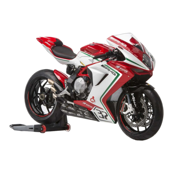
- Page 1 USER’S MANUAL M A N U A L E D E L L’ U T E N T E 675 RC 800 RC...
- Page 2 Manuale dell’utente Versione Italiana...
- Page 3 F3 al di sopra di qualsiasi moda passeggera, dandole così il privilegio di essere considerata un oggetto unico al mondo. Se desiderasse ulteriori informazioni, non esiti a contattare il Servizio Assistenza Clienti MV Agusta. Buon divertimento! Giovanni Castiglioni...
- Page 4 INDICE GENERALE cap. Descrizione argomenti pag. cap. Descrizione argomenti pag. INFORMAZIONI GENERALI 4.1. Uso della motocicletta 1.1. Scopo del manuale 4.2. Rodaggio 1.2. Simbologia 4.3. Avviamento motore 1.3. Certificato di Consegna 4.4. Selezione e modifica delle funzioni display 1.4. Dati di identificazione 4.4.1.
- Page 5 INDICE GENERALE cap. Descrizione argomenti pag. 5.2. Tabella delle regolazioni 5.3. Regolazione leva freno anteriore 5.4. Regolazione specchietti retrovisori 5.5. Regolazione sospensione anteriore 5.5.1. Precarico molla (sospensione anteriore) 5.5.2. Dispositivo idraulico di frenatura in estensione (sospensione anteriore) 5.5.3. Dispositivo idraulico di frenatura in compressione (sospensione anteriore) 5.6.
- Page 6 PC, sia dotato di sistema Windows che Mac. Vi raccomandiamo di leggere attentamente il Manuale prima di utilizzare la moto e di sincerarVi che chiunque utilizzi la moto abbia prima fatto lo stesso. Copyright MV AGUSTA Motor Spa Tutti i diritti riservati - 5 -...
- Page 7 INFORMAZIONI GENERALI 1.2. Simbologia Le parti di testo di particolare importanza, relative alla sicurezza della persona e all’integrità della moto- cicletta, sono evidenziate con i seguenti simboli: Pericolo - Attenzione: la mancata o incompleta osservanza di queste prescrizioni può comportare pericolo grave per la propria incolumità e per quella di altre persone. Cautela - Precauzione: la mancata o incompleta osservanza di queste prescrizioni può...
- Page 8 INFORMAZIONI GENERALI 1.3. Certificato di Consegna Al momento della consegna della moto, il Vs. Concessionario vi ha consegnato il Certificato di Garanzia e Pre-Consegna. Vi preghiamo di conservarlo unitamente ai documenti della moto ed ai futuri tagliandi di manutenzione che vi verranno via via consegnati in occasione degli interventi previsti.
- Page 9 INFORMAZIONI GENERALI 2) numero di matricola motore 1) numero di matricola telaio 3) dati di omologazione 1.4. Dati di identificazione 1) numero di matricola telaio 2) numero di matricola motore 3) dati di omologazione Identificazione motocicletta Si consiglia di annotare i dati principali negli spazi La motocicletta è...
- Page 10 INFORMAZIONI GENERALI Identificazione chiave della motocicletta Viene fornita, in duplice copia, una chiave da utilizzare sia per l’avviamento che per l’azionamento di tutte le serrature. Custodire in luogo sicuro la copia di scorta. La conoscenza del numero di identificazione chiave è essenziale nel caso in cui si renda necessario richiede- re un duplicato della chiave a ricambio.
- Page 11 INFORMAZIONI GENERALI Procedere alla rimozione del fianchetto serbatoio destro sfilandolo verso la parte anteriore della moto. Dopo avere rimosso il fianchetto serbatoio, è possibile accedere alla targhetta codice colore posta sul serba- targhetta codice colore toio. Su questa targhetta è possibile individuare il codi- ce colore della motocicletta, il quale determina la colo- razione delle parti della carrozzeria.
- Page 12 INFORMAZIONI SULLA SICUREZZA 2.1. GARANZIA DEL vEICOLO con parti di ricambio e/o accessori origi- nali Mv Agusta e montati dal Servizio di ATTENZIONE Assistenza Tecnica presso Le ricordiamo che la garanzia non opera Concessionario Mv Agusta. nel caso di uso del veicolo in competi-...
- Page 13 Concessionario della rete MV Agusta. che come mano d’opera. La MV Agusta Le raccomanda che ogni interven- to sul veicolo, sia che si tratti di Tagliandi di Manutenzione che di qualsivoglia altro intervento...
- Page 14 Manutenzione, nel Manuale di Officina ed in aspettative. eventuali Circolari Tecniche pubblicate dalla MV Troverà i Tagliandi suddetti in calce al Libretto di Agusta S.p.A. in quanto MV Agusta garantisce la Garanzia. corretta esecuzione di ogni intervento solo ed Conservi sempre il Libretto di Garanzia contenen-...
- Page 15 INFORMAZIONI SULLA SICUREZZA 2.3. CARICO vEICOLO ATTENZIONE Dato che il carico ha un impatto enorme sulla manovrabilità, la frenata, le presta- Il veicolo è progettato per l’impiego da parte del zioni e le caratteristiche di sicurezza del pilota e di un eventuale passeggero. Per un utiliz- vostro mezzo, tenere sempre presenti le zo in piena sicurezza e nel rispetto delle norme seguenti precauzioni.
- Page 16 COMANDI E STRUMENTI 3.1. Posizione comandi e strumenti Strumentazione e spie (§3.7.) Specchietto retrovisore (§5.1.) Specchietto retrovisore (§5.1.) Leva comando frizione (§5.1.) Leva comando freno anteriore (§5.1.) Comandi elettrici semimanubrio sinistro (§3.3.) Comando acceleratore (§3.4.) Interruttore di accensione e bloccasterzo (§3.5.) Comandi elettrici semimanubrio destro (§3.4.) Tappo serbatoio carburante (§4.5.) Leva comando cambio (§3.6.
- Page 17 COMANDI E STRUMENTI 3.2. Cavalletto laterale Il cavalletto laterale è dotato di un interruttore di sicurezza che impedi- sce al motociclo di mettersi in mar- cia con il cavalletto abbassato. Nel caso in cui, a motore avviato e nella condizione cavalletto abbassato, si azioni il cambio per porsi in movimento, l’interruttore...
- Page 18 COMANDI E STRUMENTI 3.3. Comandi semimanubrio sinistro Pulsante lampeggio fari Premere il pulsante a ripetizione. Pulsante SET/OK Premere per modificare le funzioni del cruscotto (§ 4.4). Pulsante abbagliante/anabbagliante Pulsante in fuori : anabbagliante Pulsante in dentro : abbagliante Pulsante avvisatore acustico Premere per attivare l’avvisatore acustico.
- Page 19 COMANDI E STRUMENTI Pulsante Lampeggio Faro Questa funzione serve a richiamare l’attenzione degli altri utenti della strada in caso di possibili situazioni di pericolo; con l’abbagliante acceso tale funzione non è attiva. Pulsante SET/OK Il pulsante SET consente di selezionare le cifre del display per effettuare le regolazioni, mentre il pulsante OK consente di confermare le cifre impostate.
- Page 20 COMANDI E STRUMENTI 3.4. Comandi semimanubrio destro Leva freno anteriore Avvicinare alla manopola per azionare il freno anteriore. Interruttore stop motore Se azionato arresta il motore e ne impedisce l’avviamento. Pulsante avviamento motore Premuto avvia il motore. Va rilasciato appena avviato. Con moto- re avviato, ripremendo, si selezionano le funzioni del display.
- Page 21 COMANDI E STRUMENTI Interruttore Stop Motore Questa funzione permette di arrestare il motore; in questo modo viene disattivato il circuito di accensione impedendo il riavvio del motore. Per poter effettuare l’avviamento riportare il pulsante in posizione di riposo. NOTA: In qualsiasi condizione, utilizzare questo dispositivo per l’arresto del motore. Pulsante Avviamento Motore Questo dispositivo consente l’avviamento del motore;...
- Page 22 In caso di anomalia, si raccomanda di proseguire la marcia a velocità ridotta e contattare un centro assistenza auto- rizzato Mv Agusta. In caso di disattivazione, procedere con la selezione della funzione ABS (vedi § 4.4.7.).
- Page 23 COMANDI E STRUMENTI 3.5. Interruttore accensione e bloccasterzo ATTENZIONE Non applicare portachiavi o altri oggetti alla chiave di accensione per non creare ostacoli alla rotazione dello sterzo. ATTENZIONE Non tentare di cambiare alcuna funzione del- l’interruttore durante la marcia; si potrebbe incorrere nella perdita di controllo del mezzo.
- Page 24 COMANDI E STRUMENTI Posizione “OFF” Tutti i circuiti elettrici sono disattivati. La chiave può es- sere estratta. Posizione “ON” Tutti i circuiti elettrici sono attivati, la strumentazione e le spie eseguono l’autodiagnosi; il motore può essere avviato. La chiave non può essere estratta. CAUTELA Non lasciare la chiave sulla posizione “ON”...
- Page 25 COMANDI E STRUMENTI Posizione “LOCK” Ruotare il manubrio a destra o a sinistra. Premere leg- germente la chiave e contemporaneamente ruotarla in posizione “LOCK”. Tutti i circuiti elettrici sono disattivati e lo sterzo è bloc- cato. La chiave può essere estratta. Lato Destro Lato Sinistro - 24 -...
- Page 26 Mv Agusta consiglia di utilizzare la leva frizione in tutte le circostanze sopra citate, in particolare quando il numero di giri del motore si avvici- na al regime di intervento del limitatore.
- Page 27 COMANDI E STRUMENTI 3.7. Strumentazione e spie Gli strumenti e le spie si attivano ruotando la chiave di accensione in posizione “ON”. Dopo un check-up iniziale (~ 7 secondi) le informazioni corrispondono alle condizioni generali della motocicletta in quel momento. Display contagiri Spie luminose di indicazione...
- Page 28 ABS sia attivata indicatori di direzione. (vedi §4.4.7.). In caso positivo, proseguire la marcia a velocità ridotta e contattare un cen- Spia luce abbagliante (blu) tro assistenza autorizzato MV Agusta. Si accende quando è attivata la luce abbagliante. - 27 -...
- Page 29 Indica la percorrenza parziale; da 0 a 999.9 (Km o mi) necessario rabboccarlo, rivolgersi presso un centro Contachilometri parziale 2 “TRIP 2” assistenza autorizzato MV Agusta (vedi § 3.8). Se Indica la percorrenza parziale; da 0 a 999.9 (Km o mi) l’indicazione compare nonostante il livello sia cor-...
- Page 30 Motul Chain Lube Road – : Per la reperibilità del prodotto consigliato, MV Agusta consiglia di rivolgersi direttamente ai propri con- cessionari autorizzati. Il motore del motociclo F3 è stato sviluppato con olio motore Motul 7100 4T 5W40. Qualora il lubrificante descritto non fosse reperibile, MV Agusta consiglia l’utilizzo di olii completamente sintetici con caratteristiche...
- Page 31 4.1. Uso della motocicletta In questa sezione vengono esposti gli argomenti principali per il corretto uso della motocicletta. ATTENZIONE Il vostro motociclo presenta elevate caratteristiche di potenza e prestazioni; per il suo uso è pertanto richiesto un’adeguato livello di conoscenza del mezzo. Al momento del primo utilizzo di questo veicolo è...
- Page 32 4.2. Rodaggio Cautela - Precauzione: l’inosservanza delle indicazioni di seguito riportate può pregiudi- 5500-6000 rpm care la durata e le prestazioni della motoci- cletta. È uso comune considerare il rodaggio come una fase applicata al solo motore. In realtà esso va considerato anche per altre parti importanti della moto, in particola- re i pneumatici, i freni, la catena di trasmissione, ecc.
- Page 33 Da 500 a 1000 Km (da 300 a 600 mi) Durante questa percorrenza evitare di mantenere a lungo il motore sotto sforzo. 8000-9000 rpm Da 1000 a 2500 Km (da 600 a 1600 mi) Durante questa percorrenza è possibile pretendere maggiori prestazioni dal motore, senza tuttavia supera- re il regime di rotazione indicato.
- Page 34 4.3. Avviamento motore ATTENZIONE: Far funzionare il motore in un ambiente chiuso può essere pericoloso. I gas di scarico contengono monossido di carbo- nio, un gas incolore ed inodore che può pro- vocare decessi o infortuni gravi. Fare funzio- nare il motore solo all’esterno, all’aria aperta. Ruotando l’interruttore d’accensione in posizione “ON”, la strumentazione e le spie eseguono l’autodia- gnosi;...
- Page 35 è stato riscontrato il malfunzionamento. Premendo il pulsante “OK”, il cruscotto passa alla modalità “RUN”. ATTENZIONE In caso di segnalazione di un guasto al veico- lo, non avviare il motore e contattare un cen- tro assistenza autorizzato Mv Agusta. - 34 -...
- Page 36 Procedura di avviamento Pulsante “START” Premere il pulsante di avviamento motore senza ruotare la manopola dell’acceleratore. Appena il motore si è avviato rilasciare il pulsante. Cautela - Precauzione: • Per evitare danni all’impianto elettrico non azionare l’avviamento per più di 5 secondi consecutivi.
- Page 37 4.4. Selezione e modifica delle funzioni display La strumentazione prevede la possibilità di interveni- re su alcuni dei parametri principali di misurazione. Le operazioni possibili sono : - Selezione delle modalità di funzionamento: “RUN” (Contachilometri) “SPEED LIMITER” (Limitatore velocità) “TC” (Controllo trazione) “CHRONO”...
- Page 38 4.4.1. Selezione funzioni display La selezione riguarda le seguenti modalità di funzionamento: • “RUN” (Contachilometri) • “SPEED LIMITER” (Limitatore velocità) • “TC” (Controllo trazione) • “CHRONO” (Cronometro) • “QUICK SHIFT” (Cambio rapido) • “ABS” (Sistema antibloccaggio) • “CLOCK” (Orologio) La visualizzazione delle varie modalità di funzionamento avviene premendo il pulsante “SET”...
- Page 39 Modalità “RUN” Oltre alla funzione tachimetro, sul display vengono visualizzate le seguenti funzioni (vedi §4.4.2.): • Contachilometri Totale “TOTAL” • Contachilometri Parziale 1 “TRIP 1” In alternativa: • Contachilometri Totale “TOTAL” • Contachilometri Parziale 2 “TRIP 2” Modalità “SPEED LIMITER” Questa modalità...
- Page 40 Modalità “TC” La presente funzione permette di adattare il livello del controllo di trazione del motore secondo le proprie esi- genze di guida (vedi §4.4.4.). Modalità “ChRONO” Questa modalità permette l’attivazione della funzione cronometro e l’immagazzinamento dei dati misurati (vedi §4.4.5.). Le funzioni visualizzate diventano: •...
- Page 41 Modalità “QUICK ShIFT” Questa modalità permette di attivare o disattivare la fun- zione di cambio rapido del rapporto di trasmissione (vedi §4.4.6.). Modalità “ABS” La presente funzione permette di attivare o disattivare il sistema antibloccaggio ABS del sistema frenante (vedi §4.4.7.).
- Page 42 Modalità “CLOCK” La presente funzione consente di modificare l’orario (ore e minuti) riportato sul cruscotto (vedi §4.4.8.). - 41 -...
- Page 43 4.4.2. Azzeramento delle funzioni contachilometri parziali I valori delle funzioni “TRIP 1” e “TRIP 2” possono esse- re azzerati nel modo seguente. ATTENZIONE Le operazioni di modifica o regolazione delle funzioni display devono essere eseguite con motore spento, cambio in folle, motocicletta ferma e piedi a terra.
- Page 44 Premere il pulsante “OK” per un tempo inferiore a tre secondi fino alla visualizzazione della funzione conta- chilometri parziale 2 (“TRIP 2”). Premendo ora il pulsante “OK” per un tempo supe- riore a tre secondi il valore “TRIP 2” si azzera. - 43 -...
- Page 45 4.4.3. Modalità “SPEED LIMITER” Al momento dell’accensione del motore la funzione “SPEED LIMITER” è disattivata. Per attivarla occorre eseguire le seguenti operazioni: Premere il pulsante “SET” per accedere alla moda- lità “SPEED LIMITER”. Il valore mostrato della velocità massima (corrispondente alla velocità attuale del vei- colo) inizia a lampeggiare.
- Page 46 Premendo il pulsante “OK” per un tempo superiore a tre secondi, il valore prescelto della velocità massima viene confermato. La cifra indicata smette di lampeg- giare e il cruscotto ritorna alla modalità “RUN”. Se invece si preme il pulsante “SET” per un tempo superiore a tre secondi, la funzione “SPEED LIMITER”...
- Page 47 4.4.4. Modalità “TC” Premere il pulsante “SET” per accedere alla moda- lità “TC”, quindi premere il pulsante “OK” per un tempo inferiore ai tre secondi fino alla visualizzazione della scritta “TC LEVEL”. L’attuale livello del controllo di tra- zione corrisponde al valore visualizzato sul display. NOTA: Le operazioni di modifica o regolazione del livello del controllo di trazione possono essere eseguite con il veicolo in movimento.
- Page 48 4.4.5. Cronometro Acquisizione dei tempi sul giro Dopo aver attivato la funzione cronometro (modalità “CHRONO”) è possibile iniziare l’acquisizione dei dati relativi ai tempi di percorrenza sul giro. L’azionamento del pulsante del lampeggio faro abbagliante determina l’inizio della misurazione dei dati. I puntini che separano i minuti dai secondi e dai decimi di secondo iniziano a lampeggiare.
- Page 49 Premendo nuovamente il pulsante del lampeggio fanale abbagliante viene registrata la misurazione del tempo relativo al 1° giro percorso. Contemporanea- mente lo strumento inizia ad acquisire il tempo relativo al secondo giro. La misurazione del tempo relativo al primo giro viene conservata in memoria e rimane visualizzata sul display per dieci secondi, quindi si procede con la visualizza- zione del tempo sul giro successivo.
- Page 50 visualizzazione dei dati Terminata la fase di acquisizione tempi è possibile ese- guirne la visualizzazione. Accedere alla modalità “CHRONO”; in questa scher- mata viene visualizzato il tempo sul giro più veloce (“BEST LAP”) ed il tempo sull’ultimo giro percorso (“LAST LAP”). ATTENZIONE Le operazioni di modifica o regolazione delle funzioni display devono essere eseguite con...
- Page 51 La ripetuta pressione del pulsante del lampeggio fanale abbagliante consente di visualizzare in sequen- za tutti i tempi precedentemente acquisiti a partire dal- l’ultimo giro memorizzato. Al termine della visualizzazione dei dati, la pressione del pulsante “SET” consente di tornare alla modalità “LAPS VIEW”...
- Page 52 Cancellazione dei dati L’operazione di cancellazione dei dati memorizzati si esegue applicando le seguenti procedure: ATTENZIONE Le operazioni di modifica o regolazione delle funzioni display devono essere eseguite con motore spento, cambio in folle, motocicletta ferma e piedi a terra. è vietato cambiare le impostazioni del display durante la marcia.
- Page 53 Premendo ora il pulsante “OK” per un tempo supe- riore a tre secondi il valore viene cancellato. Se invece si preme il pulsante “SET” per un tempo infe- riore ai tre secondi la procedura di cancellazione viene interrotta. Successivamente, la pressione del pulsante del lampeggio fanale abbagliante seguita dalla pressione del pulsante “OK”...
- Page 54 Cancellazione miglior tempo: Accedere alla modalità “CHRONO” e premere il pulsante “SET” per un tempo inferiore ai tre secondi fino alla visualizzazione della scritta “BEST LAP RESET”. Premere il pulsante “OK” per un tempo inferiore a tre secondi; il valore del tempo sul giro più veloce inizia a lampeggiare.
- Page 55 Premendo ora il pulsante “OK” per un tempo supe- riore a tre secondi il valore viene cancellato. Se invece si preme il pulsante “SET” per un tempo infe- riore ai tre secondi la procedura di cancellazione viene interrotta. Al termine della cancellazione dei dati, la pressione del pulsante “SET”...
- Page 56 Premere il pulsante “OK” per un tempo inferiore a tre secondi; il display richiede la conferma per la cancella- zione di tutti i dati presenti in memoria. Premendo ora il pulsante “OK” per un tempo supe- riore a tre secondi tutti i tempi precedentemente acqui- siti vengono cancellati.
- Page 57 4.4.6. Modalità “QUICK ShIFT” Premere il pulsante “SET” per accedere alla moda- lità “QUICK SHIFT”. Il display mostra lo stato di attiva- zione della funzione cambio rapido (“ON”: attivata; “OFF”: disattivata). ATTENZIONE Le operazioni di modifica o regolazione delle funzioni display devono essere eseguite con motore spento, cambio in folle, motocicletta ferma e piedi a terra.
- Page 58 4.4.7. Selezione della funzione ABS Premere il pulsante “SET” per accedere alla moda- lità “ABS”; sul display viene visualizzata la scritta “SET- TING ABS”. ATTENZIONE Le operazioni di modifica o regolazione delle funzioni display devono essere eseguite con motore spento, cambio in folle, motocicletta ferma e piedi a terra.
- Page 59 Se invece si preme il pulsante “OK” mentre l’indica- zione lampeggia, la scritta sul display passa a “ABS OFF”. Se non si preme alcun pulsante, dopo tre secondi la selezione “ABS OFF” viene confermata; in questa con- dizione il sistema ABS è disattivato. Premere il pulsan- te “SET”...
- Page 60 4.4.8. Impostazione dell’orologio Per eseguire l’impostazione dell’orario, premere il pulsante “SET” fino alla visualizzazione della scritta “CLOCK SETTING”. ATTENZIONE Le operazioni di modifica o regolazione delle funzioni display devono essere eseguite con motore spento, cambio in folle, motocicletta ferma e piedi a terra. è vietato cambiare le impostazioni del display durante la marcia.
- Page 61 Dopo avere eseguito l’impostazione della cifra del- l’ora, il cruscotto passa automaticamente all’impostazio- ne della cifra dei minuti. La cifra dei minuti inizia a lam- peggiare. Premendo il pulsante “OK” per un tempo inferiore a tre secondi, la cifra dei minuti viene incrementata pas- sando al valore successivo.
- Page 62 4.4.9. Selezione della mappatura centralina Sui modelli F3, è possibile selezionare differenti map- pature della centralina che permettono di ottenere caratteristiche variabili di potenza e prestazioni a secon- da del tipo di utilizzo del veicolo. NOTA Le operazioni di selezione della mappatura centralina possono essere eseguite con il vei- colo in movimento.
- Page 63 Impostazione della mappatura personalizzata Premere il pulsante di avviamento a motore acceso fino a selezionare la mappatura “C” della centralina (mappatura personalizzata). ATTENZIONE: Le operazioni di impostazione della mappatura personalizzata devono esse- re eseguite con cambio in folle, motocicletta ferma e piedi a terra. è vietato cambiare le impostazioni del display durante la marcia.
- Page 64 Premere il pulsante “SET” per un tempo inferiore ai tre secondi. Sul display compare l’attuale impostazione selezionata per la sensibilità del comando accelerato- Premere il pulsante “OK” per un tempo inferiore ai tre secondi; l’indicazione sul display inizia a lampeggia- La ripetuta pressione del pulsante “OK”...
- Page 65 Premere il pulsante “OK” per un tempo superiore ai tre secondi; la nuova impostazione selezionata viene confermata. L’indicazione sul display smette di lampeg- giare e dopo alcuni secondi ritorna al menu “GAS SEN- SITIVITy”. é ora possibile passare alla regolazione del parametro successivo.
- Page 66 Premere il pulsante “SET” per un tempo inferiore ai tre secondi. Sul display compare l’attuale impostazione selezionata per la coppia massima del motore. Premere il pulsante “OK” per un tempo inferiore ai tre secondi; l’indicazione sul display inizia a lampeggia- La ripetuta pressione del pulsante “OK”...
- Page 67 Premere il pulsante “OK” per un tempo superiore ai tre secondi; la nuova impostazione selezionata viene confermata. L’indicazione sul display smette di lampeg- giare e dopo alcuni secondi ritorna al menu “MAX ENGINE TORQUE”. Freno motore: Premere il pulsante “OK” per un tempo inferiore ai tre secondi fino alla visualizzazione della scritta “ENGINE BRAKE”.
- Page 68 Premere il pulsante “SET” per un tempo inferiore ai tre secondi. Sul display compare l’attuale impostazione selezionata per il freno motore. Premere il pulsante “OK” per un tempo inferiore ai tre secondi; l’indicazione sul display inizia a lampeggia- La ripetuta pressione del pulsante “OK” per un tempo inferiore ai tre secondi permette di visualizzare in sequenza le seguenti impostazioni: •...
- Page 69 Premere il pulsante “OK” per un tempo superiore ai tre secondi; la nuova impostazione selezionata viene confermata. L’indicazione sul display smette di lampeg- giare e dopo alcuni secondi ritorna al menu “ENGINE BRAKE”. Erogazione del motore: Premere il pulsante “OK” per un tempo inferiore ai tre secondi fino alla visualizzazio- ne della scritta “ENGINE RESPONSE”.
- Page 70 Premere il pulsante “SET” per un tempo inferiore ai tre secondi. Sul display compare l’attuale impostazione selezionata per l’erogazione del motore. Premere il pulsante “OK” per un tempo inferiore ai tre secondi; l’indicazione sul display inizia a lampeggia- La ripetuta pressione del pulsante “OK” per un tempo inferiore ai tre secondi permette di visualizzare in sequenza le seguenti impostazioni: •...
- Page 71 Premere il pulsante “OK” per un tempo superiore ai tre secondi; la nuova impostazione selezionata viene confermata. L’indicazione sul display smette di lampeg- giare e dopo alcuni secondi ritorna al menu “ENGINE RESPONSE”. Limitatore giri motore: Premere il pulsante “OK” per un tempo inferiore ai tre secondi fino alla visualizzazio- ne della scritta “RPM LIMITER”.
- Page 72 Premere il pulsante “SET” per un tempo inferiore ai tre secondi. Sul display compare l’attuale impostazione selezionata per il limitatore giri motore. Premere il pulsante “OK” per un tempo inferiore ai tre secondi; l’indicazione sul display inizia a lampeggia- La ripetuta pressione del pulsante “OK” per un tempo inferiore ai tre secondi permette di visualizzare in sequenza le seguenti impostazioni: •...
- Page 73 Premere il pulsante “OK” per un tempo superiore ai tre secondi; la nuova impostazione selezionata viene confermata. L’indicazione sul display smette di lampeg- giare e dopo alcuni secondi ritorna al menu “RPM LIMI- TER”. Premere il pulsante “OK” per un tempo inferiore ai tre secondi fino alla visualizzazione del display in moda- lità...
- Page 74 “RUN”. Le luci di emergenza degli indicatori di direzione iniziano a lampeggiare. ATTENZIONE Nel caso in cui l’autodiagnosi evidenzi la pre- senza di un guasto a veicolo fermo, non avviare il motore e contattare un centro assi- stenza autorizzato Mv Agusta. - 73 -...
- Page 75 Nel caso in cui venga segnalata la presenza di un guasto durante l’utilizzo del veicolo, non proseguire la marcia e contattare un centro assistenza autorizzato Mv Agusta. Al momento dell’arresto del veicolo, sul display viene visualizzato il messaggio di errore che evidenzia il grup- po o il componente della motocicletta su cui è...
- Page 76 Nel caso in cui fosse necessario rabboccarlo, rivolgersi presso un centro assistenza autorizzato Mv Agusta (vedi § 3.8). Se l’indicazione compare nonostante il livello sia corretto, non prose- guire la marcia e contattare un centro assi- stenza autorizzato Mv Agusta. - 75 -...
- Page 77 4.5. Rifornimento carburante Pericolo - Attenzione: la benzina e i suoi vapo- ri sono estremamente infiammabili e nocivi. Evitare il contatto e l’inalazione. Durante il rifornimento spegnere il motore, non fumare, tenere lontane fiamme, scintille e fonti di calore. Effettuate il rifornimento all’a- perto o in locale ben ventilato.
- Page 78 ATTENZIONE Un riempimento eccessivo del serbatoio può far traboccare il carburante a causa dell’e- spansione dovuta al calore del motore o all’esposizione della motocicletta alla luce solare. Eventuali fuoriuscite di carburante possono provocare incendi. Il livello del carburante nel serbatoio non deve mai superare la base del bocchettone di riempimento. Cautela-Precauzione: asciugare subito con un panno pulito l’eventuale carburante versa- to, in quanto può...
- Page 79 4.6. Accesso al vano portaoggetti Inserire la chiave. Premere la sella passeggero nella parte termi- nale e contemporaneamente ruotare la chiave in senso antiorario. Sollevare la sella passeggero dall’estremità posteriore e farla ruotare come mostrato in figura. Per il rimontaggio del particolare osservare le seguenti indicazioni: •...
- Page 80 “SIDE STAND” scompaia dal cruscotto; in ogni caso verificare che il caval- letto sia rientrato. Se si nota una disfunzione, fare controllare l’impianto da un concessio- nario Mv Agusta prima di utilizzare il mezzo. - 79 -...
- Page 81 Sosta con cavalletto posteriore Inserire il perno del cavalletto nel foro del- l’asse ruota posteriore dal lato sinistro della motocicletta; appoggiare il cavallet- to al suolo e facendo forza su di esso sol- levare il veicolo fino al raggiungimento della condizione di stabilità. ATTENZIONE Questa operazione deve essere eseguita da due persone.
- Page 82 Tuttavia, poiche’ una errata regolazione di componen- ti particolarmente importanti puo’ creare una situazio- ne di pericolo, alcune di queste regolazioni sono riser- vate soltanto ai Centri Assistenza MV Agusta. ATTENZIONE Tutte le regolazioni devono essere effettua- te a veicolo fermo.
- Page 83 REGOLAZIONI (B) Regolazione specchietto retrovisore (§5.4.) (D) Regolazione sospensione posteriore (§5.6.) (F) Orientamento faro (§5.7.) (E) Regolazione (C) Regolazione sospensione anteriore (§5.5.) catena (§5.2.) (A) Regolazione leva freno anteriore (§5.3.) - 82 -...
- Page 84 REGOLAZIONI 5.2. Tabella delle regolazioni A - Regolazione leva freno anteriore: per otti- D - Regolazione sospensione posteriore: per adattare la risposta alle preferenze del motocicli- mizzare la presa in funzione delle esigenze del sta si possono regolare: motociclista (§5.3). - altezza assetto - precarico molla B - Regolazione specchietti retrovisori: per...
- Page 85 REGOLAZIONI 5.3. Regolazione leva freno anteriore Ruotare il registro di regolazione della leva per modificarne la posizione. In senso orario: la leva si avvicina alla manopola. In senso antiorario: la leva si allontana dalla manopola. 5.4. Regolazione specchietti retrovisori Premere nei punti evidenziati per regolare la posi- zione nelle quattro direzioni.
- Page 86 REGOLAZIONI 5.5. Regolazione sospensione anteriore Dispositivo idraulico di frenatura in estensione NOTA: La regolazione delle sospensioni deve essere preferibilmente effettuata con il serbatoio carburante pieno. 5.5.1. Precarico molla (sospensione anteriore) La regolazione deve essere effettuata partendo dalla posizione standard. Per trovare tale posizio- ne, occorre ruotare in senso antiorario fino a fondo corsa, quindi in senso orario fino alla posi- zione standard (vedi tabella allegata).
- Page 87 REGOLAZIONI 5.5.2. Dispositivo idraulico di frenatura in 5.5.3. Dispositivo idraulico di frenatura in compressione (sospensione anteriore) estensione (sospensione anteriore) La regolazione deve essere effettuata partendo La regolazione deve essere effettuata partendo dalla posizione standard. Per trovare tale posizio- dalla posizione standard. Per trovare tale posizio- ne, occorre ruotare in senso orario fino a fondo ne, occorre ruotare in senso orario fino a fondo corsa, quindi in senso antiorario fino alla posizio-...
- Page 88 REGOLAZIONI 5.6. Regolazione sospensione posteriore ATTENZIONE: L’ammortizzatore contiene gas ad alta pressione. Non tentare in alcun modo di effettuarne lo smontaggio. CAUTELA: Per valutare la taratura della sospensione posteriore non agire in nessun modo sul portatarga. Esso sarebbe sicuramente soggetto a danneggiamento. NOTA: Al momento della consegna, la sospensione posteriore viene regolata nella confi- gurazione standard (vedi tabella allegata).
- Page 89 REGOLAZIONI 5.6.1. Dispositivo idraulico di frenatura in estensione (sospensione posteriore) La regolazione deve essere effettuata partendo dalla posizione standard. Per trovare tale posizio- ne, occorre ruotare in senso orario fino a fondo corsa, quindi in senso antiorario fino alla posizio- ne standard (vedi tabella).
- Page 90 REGOLAZIONI 5.6.2. Dispositivo idraulico di frenatura in compressione (sospensione posteriore) La regolazione deve essere effettuata partendo dalla posizione standard. Per trovare tale posizio- ne, occorre ruotare in senso orario fino a fondo corsa, quindi in senso antiorario fino alla posizio- ne standard (vedi tabella).
- Page 91 REGOLAZIONI 5.7. Regolazione proiettore anteriore Porre il veicolo a 10 metri di distanza da una parete verticale. Assicurarsi che il terreno sia piano e che l’asse ottico del proiettore sia perpendicolare alla parete. Il veicolo deve trovarsi in posizione verticale. Misurare l’altezza del centro del proiettore da terra e ripor- tare sulla parete una crocetta alla medesima altezza.
- Page 92 REGOLAZIONI La regolazione verticale del fascio luminoso può essere effettuata agendo sulla vite raffigurata a lato. In senso orario: il gruppo ottico si inclina verso l’alto. In senso antiorario: il gruppo ottico si inclina verso il basso. L’inclinazione può essere Senso orario variata di ±4°...
- Page 93 Voi acquistato. I modelli MV Agusta vengono esportati in numerosi Paesi, nei quali valgono norme differenti in relazione al Codice della Strada ed alle procedure di omologazione. Contando sulla Vostra comprensione, MV Agusta Motor S.p.A.
- Page 94 User’s manual English Version...
- Page 95 F3 to soar above passing fash- ions, giving it the privilege of being considered a unique item. For further information, please feel free to contact the MV Agusta Customer Care Service. Have a good time!
- Page 96 CONTENTS chap. Subjects covered page chap. Subjects covered page OPERATION GENERAL INFORMATION 4.1. Using the motorcycle 1.1. Purpose of the manual 4.2. Running-in 1.2. Symbols 4.3. Starting the engine 1.3. Delivery certificate 4.4. Selecting and setting the display functions 36 1.4.
- Page 97 CONTENTS chap. Subjects covered page 5.2. Table of adjustments 5.3. Adjusting the front brake lever 5.4. Adjusting the rearview mirrors 5.5. Adjusting the front suspension 5.5.1. Spring preload (front suspension) 5.5.2. Rebound damper (front suspension) 5.5.3. Compression damper (front suspension) 5.6.
- Page 98 PC, equipped either with Windows or Mac operative system. We recommend to carefully read the User’s Manual before using your motorcycle, and to make sure that anyone who uses the motorcycle had previously made the same. Copyright MV AGUSTA Motor Spa All rights reserved - 5 -...
- Page 99 GENERAL INFORMATION 1.2. Symbols Sections of text that are particularly important in terms of personal safety or possible damage to the motorcycle are marked with the following symbols: Danger - Failure to observe these prescriptions, even in part, may pose a serious hazard to the driver’s and other people’s safety.
- Page 100 GENERAL INFORMATION 1.3. Delivery certificate When delivering the bike, your Dealer has also supplied the Warranty and Pre-Delivery Certificate. We recommend to keep it together with the motorcycle docu- ments and with the service coupons that are given at the moment of servicing the bike.
- Page 101 GENERAL INFORMATION 2) engine serial number 1) vehicle identification number 3) homologation data 1.4. Identification data 1) vehicle identification number 2) engine serial number 3) homologation data Motorcycle identification We recommend writing down the main numbers The motorcycle is identified by the vehicle identi- fication number.
- Page 102 GENERAL INFORMATION Motorcycle key identification A key is supplied in duplicate for both the ignition and all the locks. Keep the duplicate in a safe place. When placing orders for spare keys, you may be requi- red to provide the key identification number. It is advised to note this number in the following space: KEY No.: Identification of motorcycle colour combination...
- Page 103 GENERAL INFORMATION Remove the fuel tank right-hand side fairing by pulling it towards the front part of the motorcycle. After removing the fuel tank right-hand side fairing, it is possible to get to the colour code label. On this label Colour code label you can read the motorcycle colour combination, which determines the painting of the bodywork parts.
- Page 104 (lubricants and liquids, MV Agusta accessories fitted by the spark plugs, clutch, filters, chain, crown customer service at a MV Agusta dealer. wheel, pinion, brake pads, brake discs, - 11 -...
- Page 105 MV Agusta S.p.A. may not be Remember that, as required by law, this warranty considered liable for any damage incur- is provided directly by your MV Agusta dealer.
- Page 106 Always store the warranty booklets containing the rate according to technical and procedural stan- certificates stamped by the MV Agusta dealer and dards set out by MV Agusta and only use genuine the relative tax invoices and deliver it to the new spare parts and accessories.
- Page 107 SAFETY INFORMATION 2.3. VEHICLE LOAD WARNING Since the load can strongly affect han- dling, braking, performance and safety Your motorcycle is designed for use by the rider characteristics of your motorcycle, you and it can also seat a passenger. should always keep in mind the follow- To use the vehicle in complete safety and in ing warnings.
- Page 108 CONTROLS AND INSTRUMENTS 3.1. Location of controls and instruments Instruments and warning lights (§3.7.) Rearview mirror (§5.1.) Rearview mirror (§5.1.) Clutch lever (§5.1.) Front brake lever (§5.1.) Left handlebar electrical controls (§3.3.) Throttle twist grip (§3.4.) Ignition switch and steering lock (§3.5.) Right handlebar electrical controls (§3.4.) Fuel tank cap (§4.5.) Gear lever (§3.6.
- Page 109 CONTROLS AND INSTRUMENTS 3.2. Sidestand The sidestand is equipped with a safety switch that prevents the motorcycle from moving off while the stand is down. If the rider attempts to engage the gears while the engine is running and the stand is down, the switch automatically turns off the engine by cutting the current supply.
- Page 110 CONTROLS AND INSTRUMENTS 3.3. Handlebar controls, left side High beam flasher button Press the button repeatedly. SET/OK button Press to change the dashboard functions (§ 4.4). Low/high beam button Button not pressed in : low beam Button pressed in : high beam Horn button Press to operate the warning horn.
- Page 111 CONTROLS AND INSTRUMENTS High beam flasher button It is used to attract the attention of other road users in case of danger. When the high beam is on, the function is inactive. SET/OK button The SET button enables to select the display digits to carry out adjustments, while the OK button enables to confirm the set digits.
- Page 112 CONTROLS AND INSTRUMENTS 3.4. Handlebar controls, right side Front brake lever Pull to the lever to apply the front brake. Engine stop switch Stops the engine and prevents it from being restarted. Engine start button Starts the engine. To be released as soon as the engine starts. When the engine is running, pressing the button selects the dis- play functions.
- Page 113 WARNING If your motorcycle has toppled over or has been involved in an accident, have the working of the throttle control checked by a MV Agusta authorized center before restarting. - 20 -...
- Page 114 If there is a fault in the ABS system, it is recommended to resume riding at reduced speed and contact a MV Agusta authorized service centre. If the ABS system is turned off, follow the activation procedure described at § 4.4.7.
- Page 115 CONTROLS AND INSTRUMENTS 3.5. Ignition switch and steering lock WARNING Do not attach a ring or any other object to the ignition key as they may hinder the steering action. WARNING Never attempt to change the switch functions while riding, as you may lose control of the vehicle.
- Page 116 CONTROLS AND INSTRUMENTS OFF position All electrical circuits are deactivated. The key can be removed. ON position All electrical circuits are activated. The instruments and warning lights perform the self-diagnostic cycle. The engine can be started. The key cannot be removed. CAUTION Do not leave the key on the ON position for a long time when the engine is not running, in...
- Page 117 CONTROLS AND INSTRUMENTS LOCK position Turn the handlebar to the left or right. Press the key in gently while rotating it to the LOCK position. All electrical circuits are deactivated and the steering is locked. The key can be removed. Right side Left side - 24 -...
- Page 118 MV Agusta recommends to operate the clutch lever in all the above circumstances, especially when the engine rpm is close to the rpm-limiter inter- vention speed.
- Page 119 CONTROLS AND INSTRUMENTS 3.7. Instruments and warning lights The instruments and warning lights are activated by turning the ignition switch to the ON position. After a preliminary check (approx. 7 seconds) the displayed information reflects the current general condition of the motorcycle. Tachometer display Warning lights (§3.7.1.)
- Page 120 ABS system is activated are activated. (see §4.4.7.). In this case, resume riding at Headlights (blue) reduced speed and contact a MV Agusta It turns on when the headlights are on. authorized service centre. - 27 -...
- Page 121 It displays the total distance covered; from 0 to 999999 (Km or miles) Trip counter 1, “TRIP 1” needs to be filled up, contact a MV Agusta licensed It displays the length of a trip; from 0 to 999.9 (Km or miles) service centre (see §...
- Page 122 Motul Chain Lube Road – : MV Agusta suggests to refer directly to its authorized dealers in order to purchase the recommend- ed product. The F3 motorcycle engine has been developed with Motul 7100 4T 5W40 engine oil. If the above described lubricant is not available, MV Agusta suggests to...
- Page 123 OPERATION 4.1. Using the motorcycle This section provides the basic information needed to correctly operate the motorcycle. WARNING Your motorcycle shows high power and performance characteristics; therefore, its use requires an adequate level of knowledge of the vehicle. When you use this motorcycle for the first time, it is essential to adopt a cautious attitude.
- Page 124 OPERATION 4.2. Running-in CAUTION Failure to observe the indications provided 5500-6000 rpm below can reduce performance and shorten the life of the motorcycle. Running-in is generally considered to apply only to the engine. In fact, it should be regarded as an essential phase for other important parts such as the tyres, the brakes and the drive chain.
- Page 125 OPERATION 500 to 1000 km (300 to 600 mi) Avoid lugging or overspeeding the engine, and vary your speed frequently. 8000-9000 rpm 1000 to 2500 km (600 to 1600 mi) Higher engine performance can be demanded, but it is advisable not to exceed the engine speed shown in the figure.
- Page 126 OPERATION 4.3. Starting the engine WARNING Starting the engine in a closed place can be dan- gerous. Exhaust emissions contain carbon monoxide, a colourless and odourless gas that can lead to serious harm or even death when inhaled. Only start the engine outdoor, in the open air. As you turn the ignition switch to the ON position, the instruments and the warning lights will go through the self-diagnostic cycle;...
- Page 127 Press “OK” button to access to “RUN” mode. WARNING If a fault is deteced on the vehicle, do not start engine and contact an authorized MV Agusta centre. - 34 -...
- Page 128 OPERATION Engine start procedure START button Press the start button without turning the throttle twist grip. As soon as the engine starts, release the button. CAUTION • Do not press the start button for longer than 5 consecutive seconds, in order to avoid dam- age to the electrical equipment.
- Page 129 OPERATION 4.4. Selecting and setting the display functions Some of the main measurements of the instruments may be changed. The available options include: - Select an operating mode: “RUN” (Odometer) “SPEED LIMITER” “TC” (Traction control) “CHRONO” (Chronometer) “QUICK SHIFT” “ABS” (Antilock braking system) “CLOCK”...
- Page 130 OPERATION 4.4.1. Selecting the display functions The following settings may be changed on the display: • “RUN” (Odometer) • “SPEED LIMITER” • “TC” (Traction control) • “CHRONO” (Chronometer) • “QUICK SHIFT” • “ABS” (Antilock braking system) • “CLOCK” (Clock) To display the operating modes, press “SET”...
- Page 131 OPERATION “RUN” mode In addition to the speedometer, the display shows the following functions (see §4.4.2.): • Total odometer “TOTAL” • Trip counter 1 “TRIP 1” As an alternative: • Total odometer “TOTAL” • Trip counter 2 “TRIP 2” “SPEED LIMITER” mode This mode adjusts the maximum value of the vehicle speed to your driving requirements (see §4.4.3.).
- Page 132 OPERATION “TC” Mode This Mode adjusts the engine traction control level to your driving requirements (see §4.4.4.). “CHRONO” Mode This mode turns on the Chronometer and saves the recorded information (see §4.4.5.). The following is displayed: • Chronometer Current lap “CURRENT LAP”...
- Page 133 OPERATION “QUICK SHIFT” Mode This mode allows to turn off or on the “quick shift” func- tion of the gear change (see §4.4.6.). “ABS” Mode This mode allows to activate or deactivate the antilock braking system (ABS) (see §4.4.7.). - 40 -...
- Page 134 OPERATION “CLOCK” Mode The present function enables to change the time (hours and minutes) reported on the dashboard (see §4.4.8.). - 41 -...
- Page 135 OPERATION 4.4.2. Trip reset To reset “TRIP 1” and “TRIP 2”, proceed as follows. WARNING The display modes may be changed or set when the engine is off, the gear in neutral, the motorbike stationary with your feet on the ground.
- Page 136 OPERATION Press the “OK” key for less than three seconds until the partial speedometer 2 function (“TRIP 2”) appears on the display. By pressing the “OK” key for more than three seconds, the “TRIP 2” value will be reset to zero. - 43 -...
- Page 137 OPERATION 4.4.3. “SPEED LIMITER” mode When starting the engine, the “SPEED LIMITER” func- tion is disabled. In order to activate it, it is necessary to perform the following operations: Press “SET” in order to access to “SPEED LIMI- TER” mode. The maximum speed value shown on the display (equal to the current speed of the vehicle) starts blinking.
- Page 138 OPERATION Press “OK” for over three seconds to confirm the selected maximum speed value. The displayed digit stops blinking and the display returns to “RUN” mode. On the other hand, if you press “SET” for over three seconds, the “SPEED LIMITER” function is disabled. The display shows the “OFF”...
- Page 139 OPERATION 4.4.4. “TC” Mode Press “SET” in order to access to “TC” mode, then press “OK” for less than three seconds until “TC LEVEL” appears. The current traction control level is the same as the one shown on the display. NOTE The traction control level may be changed or set even during the use of the vehicle.
- Page 140 OPERATION 4.4.5. Chronometer Lap time recording Turn on the chronometer (“CHRONO” mode) to record the time taken to cover a lap. Press the headlight button to start recording the time. The colon that separates the minutes from the seconds and from the tenths of a second will start blinking.
- Page 141 OPERATION Press the headlight button again to record the time taken to cover the 1st lap. At the same time, the instru- ment starts recording the time taken to cover the second lap. The time measurement for the first lap is stored in the memory and is visualised on the display for ten sec- onds, after which the time measurement for the follow- ing lap appears.
- Page 142 OPERATION Data display Once all times have been recorded, they may be displayed. Access the “CHRONO” mode; the time of the faste- st lap (“BEST LAP”) and the time of the last lap (“LAST LAP”) appears on the display. WARNING The display modes may be changed or set when the engine is off, the gear must be in neutral, the motorbike must be stationary with...
- Page 143 OPERATION By repeatedly pressing the key of the flashing high beam headlight, all the times previously acquired star- ting from the last lap memorised can be displayed in sequence. Once all the data have been displayed, press the “SET” key to return to the “LAPS VIEW” mode and then to the following mode.
- Page 144 OPERATION How to delete data To delete the saved data, proceed as follows: WARNING The display modes may be changed or set when the engine is off, the gear in neutral, the motorbike stationary with your feet on the ground. Do not change the display while dri- ving.
- Page 145 OPERATION Now, press “OK” for over three seconds to delete the value. Otherwise, press “SET” for less than three seconds to stop the deletion procedure. Subsequently, by pressing the flashing high beam headlight key followed by the “OK” key for more than three seconds, all the previously acquired times can be cancelled.
- Page 146 OPERATION Resetting of best lap time: Access the “CHRONO” mode and press the “SET” key for less than three seconds until the words “BEST LAP RESET” appear on the display. Press the “OK” key for less than three seconds; the value of the fastest last lap time memorised will start fla- shing.
- Page 147 OPERATION Now, press “OK” for over three seconds to delete the value. Otherwise, press “SET” for less than three seconds to stop the deletion procedure. Once all the data have been cancelled, press the “SET” key to exit the “BEST LAP RESET” mode and then pass to the following mode.
- Page 148 OPERATION Press the “OK” key for less than three seconds; the display will ask you to confirm cancellation of all the data present in the memory. By pressing the “OK” key for more than three seconds, all the previously acquired times will be can- celled.
- Page 149 OPERATION 4.4.6. “QUICK SHIFT” Mode Press “SET” in order to access to “QUICK SHIFT” mode. The display shows the current activation state of the “quick shift” function of the gear change. WARNING The display modes may be changed or set when the engine is off, the gear in neutral, the motorbike stationary with your feet on the ground.
- Page 150 OPERATION 4.4.7. Selecting the ABS functions Press “SET” in order to access to “ABS” mode; “SETTING ABS” appears on the display. WARNING The display modes may be changed or set when the engine is off, the gear in neutral, the motorbike stationary with your feet on the ground.
- Page 151 OPERATION Otherwise, by pressing “OK” while the caption is still blinking, “ABS OFF” appears on the display. If you do not press any button, after three seconds the “ABS OFF” selection is confirmed; under this condi- tion, the ABS system is deactivated. Press “SET” to exit the “ABS”...
- Page 152 OPERATION 4.4.8. Clock settings To carry out clock settings, press the "SET" button until viewing the "CLOCK SETTING" caption. WARNING The display modes may be changed or set when the engine is off, the gear in neutral, the motorbike stationary with your feet on the ground.
- Page 153 OPERATION After having carried out the hour digit setting, the dashboard automatically switches to the minute digit setting. The minute digit begins to flash. By pressing the "OK" button for less than three seconds, the minute digit is increased by going to the following numeric value.
- Page 154 OPERATION 4.4.9. How to select the mapping of the control unit On F3 models it is possible to select different control unit mappings which allow to obtain variable power and performance characteristics based on the type of vehi- cle use. NOTE The mapping selection may be performed even during the use of the vehicle.
- Page 155 OPERATION Setting of “Custom” mapping Press the start button when the engine is switched on until selecting the mapping “C” of the control unit (“Custom” mapping). WARNING The “Custom” mapping setting operations must be performed when the the gear is in neutral and the motorbike stationary with your feet on the ground.
- Page 156 OPERATION Press “SET” for less than three seconds. The display shows the current setting for throttle control sensitivity. Press “OK” for less than three seconds; the displayed setting will start flashing. By repeatedly pressing “OK” for less than three seconds, the following settings can be displayed in sequence: •...
- Page 157 OPERATION Press “OK” for more than three seconds; the new setting will be confirmed. The displayed caption stops flashing and after a few seconds the display returns to “GAS SENSITIVITY” mode. It is now possible to pro- ceed with the setting of the following parameter. Maximum engine torque: Press “OK”...
- Page 158 OPERATION Press “SET” for less than three seconds. The display shows the current setting for maximum engine torque. Press “OK” for less than three seconds; the displayed setting will start flashing. By repeatedly pressing “OK” for less than three seconds, the following settings can be displayed in sequence: •...
- Page 159 OPERATION Press “OK” for more than three seconds; the new setting will be confirmed. The displayed caption stops flashing and after a few seconds the display returns to “MAX ENGINE TORQUE” mode. Engine brake: Press “OK” for less than three seconds until “ENGINE BRAKE”...
- Page 160 OPERATION Press “SET” for less than three seconds. The display shows the current setting for engine brake. Press “OK” for less than three seconds; the displayed setting will start flashing. By repeatedly pressing “OK” for less than three seconds, the following settings can be displayed in sequence: •...
- Page 161 OPERATION Press “OK” for more than three seconds; the new setting will be confirmed. The displayed caption stops flashing and after a few seconds the display returns to “ENGINE BRAKE” mode. Engine response: Press “OK” for less than three seconds until “ENGINE RESPONSE” appears. - 68 -...
- Page 162 OPERATION Press “SET” for less than three seconds. The display shows the current setting for engine response. Press “OK” for less than three seconds; the displayed setting will start flashing. By repeatedly pressing “OK” for less than three seconds, the following settings can be displayed in sequence: •...
- Page 163 OPERATION Press “OK” for more than three seconds; the new setting will be confirmed. The displayed caption stops flashing and after a few seconds the display returns to “ENGINE RESPONSE” mode. Engine RPM limiter: Press “OK” for less than three seconds until “RPM LIMITER”...
- Page 164 OPERATION Press “SET” for less than three seconds. The display shows the current setting for engine RPM limi- ter. Press “OK” for less than three seconds; the displayed setting will start flashing. By repeatedly pressing “OK” for less than three seconds, the following settings can be displayed in sequence: •...
- Page 165 OPERATION Press “OK” for more than three seconds; the new setting will be confirmed. The displayed caption stops flashing and after a few seconds the display returns to “RPM LIMITER” mode. Press “OK” for less than three seconds until the display switches to the “RUN”...
- Page 166 Press “OK” button to access to “RUN” mode. The direction indicator emergency lights begin to flash. WARNING If a fault is detected on the vehicle when the engine is off, do not start engine and contact an authorized MV Agusta centre. - 73 -...
- Page 167 WARNING If a fault is detected during riding, stop the vehicle and contact an authorized MV Agusta centre. After the vehicle is stopped, the display shows the warning message highlighting the vehicle part or device on which the fault has been detected.
- Page 168 If the coolant temperature is high, stop the motorbike and check the coolant level. If it needs to be filled up, contact a MV Agusta licensed service centre (see § 3.8). If the war- ning alert appears even if the level is adequa- te, stop driving and contact a MV Agusta licensed service centre.
- Page 169 OPERATION 4.5. Refuelling WARNING Petrol and its fumes are highly toxic and flam- mable. Avoid contact and inhalation. When refuelling, switch off the engine, avoid smoking, and keep away from flames, sparks and heat sources. Perform refuelling in the open air or in a well ventilated area. CAUTION: Only use fuel having the following characteristics: - Unleaded gasoline...
- Page 170 OPERATION WARNING Overfilling the tank may cause the fuel to overflow as a result of the expansion due to the heat from the engine or to exposure to sunlight. Fuel spills can catch fire. The level of the fuel in the tank must never be higher than the base of the filler. CAUTION Immediately wipe the overflown fuel with a clean cloth, to avoid damage to the painted or plastic surfaces.
- Page 171 OPERATION 4.6. Glove compartment Insert the key. Push the passenger seat downwards at the back and at the same time turn the key in a anti- clockwise direction. Lift up the passenger seat at the back end, let it slide backwards and make it rotate as shown in the figure.
- Page 172 “SIDE STAND” caption disappears from the instrument panel. In any case, make sure that the stand has been retracted. If you notice a malfunction of the side stand switch, have it controlled by your MV Agusta dealer before using the motorcycle. - 79 -...
- Page 173 OPERATION Using the rear stand Insert the stand pin into the rear wheel axle hole on the left side of the motorcy- cle. Rest the stand on the ground and, pressing down on the stand, lift the vehi- cle until it reaches a stable condition. WARNING This operation is best carried out with two people, one to...
- Page 174 However, since an incorrect adjustment of particularly important components can lead to dangerous situa- tions, some of the above adjustments must be per- formed only by authorized MV Agusta Service Centers. WARNING All adjustments must be performed when the vehicle is stationary.
- Page 175 ADJUSTMENTS (B) Rearview mirror adjustment (§5.4.) (D) Rear suspension adjustment (§5.6.) (F) Headlight adjustment (§5.7.) (E) Drive chain (C) Front suspension adjustment (§5.5.) adjustment (§5.2.) (A) Front brake lever adjustment (§5.3.) - 82 -...
- Page 176 ADJUSTMENTS 5.2. Table of adjustments A - Front brake lever adjustment: Optimizes D - Rear suspension adjustment: The following can be adjusted to adapt the response of the the grip to suit the rider’s needs (§5.3). suspension to the rider’s preference: - geometry height B - Rearview mirror adjustment: Optimizes the - spring preload...
- Page 177 ADJUSTMENTS 5.3. Adjusting the front brake lever Rotate the lever adjust to change its position. Clockwise: the lever moves closer to the handle. Counter-clockwise: the lever moves away from the handle. 5.4. Adjusting the rearview mirrors Press the mirror at the points shown in the figure to adjust its position in the four directions.
- Page 178 ADJUSTMENTS 5.5. Adjusting the front suspension Rebound damper NOTE: The adjustment of the suspen- sions must be preferably performed with the fuel tank full. 5.5.1. Spring preload (front suspension) The adjustment is obtained from the reference posi- tion, which is found by fully turning the adjusting nut counterclockwise;...
- Page 179 ADJUSTMENTS 5.5.2. Rebound damper (front suspension) 5.5.3. Compression damper (front suspension) The adjustment is obtained from the reference The adjustment is obtained from the reference position, which is found by fully turning the screw position, which is found by fully turning the screw clockwise and then counterclockwise until you clockwise and then counterclockwise until you reach the standard position (see enclosed table).
- Page 180 ADJUSTMENTS 5.6. Adjusting the rear suspension WARNING: The rear shock absorber contains highly compressed gas. Do not try to open or disassemble it in any way. CAUTION: To evaluate the rear suspension calibration do not in any way act on the plate support.
- Page 181 ADJUSTMENTS 5.6.1. Rebound damper (rear suspension) The adjustment is obtained from the reference position, which is found by fully turning the screw clockwise and then counterclockwise until you reach the standard position (see enclosed table). Rotate clockwise to increase the damping action or counterclockwise to decrease it.
- Page 182 ADJUSTMENTS 5.6.2. Compression damper (rear suspension) The adjustment is obtained from the reference position, which is found by fully turning the screw clockwise and then counterclockwise until you reach the standard position (see enclosed table). Rotate clockwise to increase the damping action or counterclockwise to decrease it.
- Page 183 ADJUSTMENTS 5.7. Headlight adjustment Place the vehicle at a distance of 10 m from a vertical wall. Make sure that the motorcycle is placed on an even horizontal surface, and that the headlight’s optical axis is perpendicular to the wall. The vehicle must be held in an upright position.
- Page 184 ADJUSTMENTS The light beam can be adjusted vertically by turn- ing the screw illustrated. If turned in a clockwise direction: the optical unit tilts upwards. If turned in an anti-clockwise direction: the optical unit tilts downwards. It can be tilted up to an angle of ±4° Clockwise from the standard position.
- Page 185 © 2017 This document may not, in whole or in part, be reproduced without prior consent, in writing, from MV Agusta Motor S.p.A. Part No. 8000C3586 Edition No. 1 - June 2017...
- Page 186 Manuel d’utilisation Version Française...
- Page 187 élève la F3 au dessus de toutes les modes passagères et lui confère le privilège d’être considérée comme un objet unique au monde. Si vous désirez plus d’information, n’hésitez pas à contacter notre Service Après-Vente MV Agusta. Bon divertissement Giovanni Castiglioni Président...
- Page 188 TABLE DES MATIÈRES Chap. Sujets abordés page Chap. Sujets abordés page UTILISATION GÉNÉRALITÉS 4.1. Utilisation de la moto 1.1. Utilité de ce livret 4.2. Rodage 1.2. Symboles 4.3. Démarrage 1.3. Certificat de livraison 4.4. Sélection et modification des fonctions 1.4. Données d’identification d’affichage INFORMATIONS SUR LA SÉCURITÉ...
- Page 189 TABLE DES MATIÈRES Chap. Sujets abordés page 5.2. Tableau des réglages 5.3. Réglage du levier de frein avant 5.4. Réglage des rétroviseurs 5.5. Réglage de la suspension avant 5.5.1. Précharge du ressort (suspension avant) 5.5.2. Dispositif hydraulique de freinage en détente (suspension avant) 5.5.3.
- Page 190 Nous vous recommandons de lire attentivement le Manuel avant d’utiliser la moto et de vous assurer que toutes les per- sonnes utilisant la moto ont lu attentivement le Manuel. Copyright MV AGUSTA Motor Spa Tous droits réservés - 5 -...
- Page 191 GÉNÉRALITÉS 1.2. Symboles Les parties du texte particulièrement importantes qui concernent la sécurité de la personne et l’intégrité de la moto, sont mises en évidences par les pictogrammes suivants: Danger - Attention: le non respect partiel ou total de ces prescriptions pourrait être sour- ce de danger pour soi-même et pour autrui.
- Page 192 GÉNÉRALITÉS 1.3. Certificat de livraison Au moment de vous remettre la moto, votre Concessionnaire vous a remis le Certificat de Garantie et de Préparation à la route. Nous vous invitons à conserver le Certificat avec les docu- ments de la moto et les coupons ou les factures qui vous seront remis à...
- Page 193 GÉNÉRALITÉS 2) numéro de série du moteur 1) numéro de série du cadre 3) données d’homologation 1.4. Données d’identification 1) numéro de série du cadre 2) numéro de série du moteur 3) données d’homologation Identification de la moto Il est conseillé de noter les données principales La moto est identifiable grâce au numéro de série dans les espaces ci-dessous: du cadre.
- Page 194 GÉNÉRALITÉS Identification des clés de la moto Une clé est fournie en double exemplaire, elle sert pour le contacteur de démarrage et pour toutes les autres serrures. Garder le double en lieu sûr. Il est indispensable de connaître le numéro d’identifica- tion de la clé...
- Page 195 GÉNÉRALITÉS Enlevez le flanc réservoir droit en le tirant vers la partie avant de la moto. Après avoir enlevé le flanc réservoir droit, on peut lire la plaque du code coleur. Cette plaque porte la mention du Plaque du code couleur code couleur de la moto qui détermine la couleur des parties de la carrosserie.
- Page 196 (lubri- accessoires d’origine Agusta fiants, liquides, bougies, embrayage, montés par le service après-vente d’un filtres, chaîne, couronne, pignon, pla- concessionnaire MV Agusta. quettes de frein, disques de freins, - 11 -...
- Page 197 MV agusta. Les opérations d’entretien programmé, y compris les premières, sont payantes, pièces et main d’œuvre. MV Agusta vous rappelle que toutes les interven- tions sur le véhicule, entretien programmé, répa- rations, réglages, remplacement de pièces, etc., - 12 -...
- Page 198 Manuel d’atelier et les Circulaires techni- répond à vos attentes. Ces coupons se trouvent à ques publiées par MV Agusta S.p.A. MV Agusta la fin du Livret de garantie. ne garantit l’intervention que si elle est effectuée Conservez toujours le Livret de garantie qui con- dans un atelier agréé, chez un concessionnaire...
- Page 199 INFORMATIONS SUR LA SÉCURITÉ 2.3. CHARGEMENT DU VÉHICULE ATTENTION Etant donné que le chargement a un impact énorme sur la mania-bilité le frei- Le véhicule a été conçu pour être utilisé par un nage, les performances et les caracté- pilote et le cas échéant un passager. Pour l'utiliser ristiques de sécurité...
- Page 200 COMMANDES ET APPAREILS 3.1. Position des commandes et appareils Appareils et voyants (§3.7.) Rétroviseurs (§5.1.) Rétroviseurs (§5.1.) Levier d’embrayage (§5.1.) Levier de frein avant (§5.1.) Commandes au guidon gauche (§3.3.) Commande accélérateur (§3.4.) Contacteur principal et verrouillage direction (§3.5.) Commandes au guidon droit (§3.4.) Bouchon du réservoir à...
- Page 201 COMMANDES ET APPAREILS 3.2. Béquille latérale La béquille latérale est équipée d’un contacteur qui empêche à la moto de démarrer avec la béquille bais- sée. Si le sélecteur de vitesses est actionné pour mettre la moto en mouvement lorsque le moteur tour- ne avec la béquille abaissée, le contacteur coupe le courant au moteur et provoque son arrêt.
- Page 202 COMMANDES ET APPAREILS 3.3. Commandes au guidon gauche Bouton de clignotement des phares Appuyer sur le bouton à répétition Poussoir SET/OK Appuyer pour modifier les fonctions de la planche de bord (§ 4.4). Inverseur code/phare Bouton sorti : feu de croisement Bouton enfoncé...
- Page 203 COMMANDES ET APPAREILS Bouton d’appel de phare Cette fonction sert pour rappeler l’attention des autres usagers de la route en présence d’une situation dange- reuse. Avec le feu de route éclairé, cette fonction est désactivée. Poussoir SET/OK Le bouton SET permet de sélectionner les chiffres de l’afficheur pour effectuer les réglages et le bouton OK permet de confirmer les chiffres configurés.
- Page 204 COMMANDES ET APPAREILS 3.4. Commandes au guidon droit Levier de frein avant Tirer vers la poignée pour actionner le frein avant. Coupe-circuit Coupe le moteur et empêche le démarrage. Bouton du démarreur Actionne le démarreur. Dès que le moteur part, il faut le relâcher. Une fois le moteur en marche, il sert pour sélectionner les fonc- tions d’affichage.
- Page 205 à partir de la position de repos qui correspond au régime de ralenti moteur. ATTENTION: Si votre moto est tombé ou a été impliqué dans un accident, le fonctionnement du commande d’accélérateur doit être vérifiée par un centre MV Agusta agréé avant de redémarrer. - 20 -...
- Page 206 être disponible lors du freinage. S'il ya un défaut dans le système ABS, il est recommandé de reprendre la course à vitesse réduite et contacter un centre d’assistance autorisé MV Agusta. Si le système ABS est désactivé, suivre la procédure d'activation décrite au § 4.4.7.
- Page 207 COMMANDES ET APPAREILS 3.5. Contacteur principal et verrouillage de direction ATTENTION Ne pas appliquer de porte-clés ou autre à la clé de contact pour ne pas risquer de gêner la rotation de la direction. ATTENTION Ne jamais chercher à changer certaines fonc- tions du contacteur en cours de route sous peine de perdre le contrôle du véhicule.
- Page 208 COMMANDES ET APPAREILS Position “OFF” Tous les circuits électriques sont coupés. La clé peut être retirée. Position “ON” Tous les circuits électriques sont branchés, les appa- reils et les voyants effectuent l’auto-diagnostic; le moteur peut démarrer. La clé peut être retirée. RAPPEL Ne pas laisser la clé...
- Page 209 COMMANDES ET APPAREILS Position “LOCK” Braquer le guidon à droite ou à gauche. Pousser légè- rement sur la clé et la tourner simultanément en position “LOCK”. Tous les circuits sont coupés et la direction est ver- rouillée. La clé peut être retirée. Côté...
- Page 210 MV Agusta recommande de tirer le levier d'embrayage dans toutes les circonstances ci-dessus, en particulier lorsque le régi- me moteur est proche de la vitesse de l'intervention du limiteur.
- Page 211 COMMANDES ET APPAREILS 3.7. Appareils et voyants Les appareils et les voyants sont activés lorsque la clé de contact est mise sur “ON”. Après un check-up initial (~7 secondes), les informations correspondent aux conditions générales de la moto à ce moment là. Ecran compte-tours Voyants lumineux indicateurs...
- Page 212 à 13500 tours/mn. s’arrêter immédiatement et Voyant Réserve carburant contacter un centre d’assi- (orange) stance autorisé MV Agusta. S’allume quand le réservoir ne contient plus que 4 litres de car- burant environ. Voyant système ABS (orange) Voyant Levier de vitesses au S'allume lorsque le système ABS...
- Page 213 à un centre d’assistance Indique le kilométrage partiel; de 0 à 999.9 (Km ou mi) autorisé MV Agusta (voir § 3.8). Si l’indication apparaît Chronomètre et que le niveau est correct, ne pas redémarrer et con- Indique les temps mesurés à...
- Page 214 Motul Chain Lube Road – : Pour la disponibilité du produit conseillé, MV Agusta conseille de s’adresser directement aux propres concessionnaires autorisés. Le moteur de la motocyclette F3 a été développé avec l'huile moteur Motul 7100 4T 5W40. Au cas où le lubrifiant décrit ne serait pas pos- sible à...
- Page 215 UTILISATION 4.1. Utilisation de la moto Cette partie du livret expose les principaux points qui permettent une utilisation correcte de la moto. ATTENTION La Votre moto montre caractéristiques élevées de puissance et de performances; pour l’utilisation, il est donc requise un niveau adéquat de connaissance du véhicule. Lors de la première utilisation de la moto, il est nécessaire de garder une attitude prudente.
- Page 216 UTILISATION 4.2. Rodage Prudence - Précautions: le non respect des indications suivantes peut porter préjudice à 5500-6000 rpm la durée et aux performances de la moto. Le rodage est communément considéré comme une phase appliquée uniquement au moteur. En réalité, il est nécessaire également pour d’autres parties impor- tantes de la moto, en particulier les pneumatiques, les freins, la chaîne de transmission etc.
- Page 217 UTILISATION De 500 à 1000 Km (de 300 à 600 mi) Pendant cette période, éviter les efforts prolongés du moteur. 8000-9000 rpm De 1000 à 2500 Km (de 600 à 1600 mi) Pendant cette période, il est possible de pousser un peu plus le moteur sans toutefois dépasser le régime indi- qué.
- Page 218 UTILISATION 4.3. Démarrage du moteur ATTENTION: Faire fonctionner le moteur dans un endroit fermé peut être dangereux. Les gaz d’é- chappement contiennent du monoxyde de carbo- ne, un gaz incolore et inodore qui peut provoquer des décès ou des états graves. Ne faire fonction- ner le moteur qu’à...
- Page 219 été détectée. Appuyer sur le bouton “OK” afin d’afficher la fonction “RUN”. ATTENTION Si un défaut a été détectée, ne pas démarrer le moteur et contacter un centre d’assistance autorisé MV Agusta. - 34 -...
- Page 220 UTILISATION Procédure de démarrage Bouton “START” Appuyer sur le bouton di démarrage du moteur sans tourner la poignée de l’accélérateur. Dès que le moteur a démarré, relâcher le bouton. Attention - précaution: • Afin de ne pas endommager l’installation électrique, ne pas actionner le démarrage pendant plus de 5 secondes de suite.
- Page 221 UTILISATION 4.4. Sélection et modification des fonctions à l’écran L’instrumentation prévoit la possibilité d’intervenir sur certains des paramètres de mesure principaux. Les opérations possibles sont: - Sélection des modalités de fonctionnement: “RUN” (Compteur kilométrique) “SPEED LIMITER” (Limiteur de vitesse) “TC” (Contrôle de la traction) “CHRONO”...
- Page 222 UTILISATION 4.4.1. Sélection des fonctions écran La sélection concerne les modes de fonctionnement suivants: • “RUN” (Compteur kilométrique) • “SPEED LIMITER” (Limiteur de vitesse) • “TC” (Contrôle de la traction) • “CHRONO” (Chronomètre) • “QUICK SHIFT” (Changement de vitesse rapide) •...
- Page 223 UTILISATION Modalité “RUN” Outre la fonction de compteur de vitesse, sur l’écran s’affichent les fonctions suivantes (voir §4.4.2.): • Compteur kilométrique Total “TOTAL” • Compteur kilométrique Partiel 1 “TRIP 1” En alternative: • Compteur kilométrique Total “TOTAL” • Compteur kilométrique Partiel 2 “TRIP 2”...
- Page 224 UTILISATION Modalité “TC” Cette fonction permet d’adapter le niveau de contrôle de la traction du moteur selon vos propres exigences de conduite (voir §4.4.4.). Modalité “CHRONO” Cette modalité permet l’actionnement de la fonction chronomètre et le stockage des données mesurées (voir §4.4.5.).
- Page 225 UTILISATION Modalité “QUICK SHIFT” Cette fonction permet de activer ou désactiver le fonc- tion de changement rapide de vitesse (voir §4.4.6.). Modalité “ABS” Ce mode de fonctionnement permet d'activer ou de désactiver le système anti-blocage de frein (ABS) (voir § 4.4.7.). - 40 -...
- Page 226 UTILISATION Modalité “CLOCK” Cette fonction permet de modifier l’horaire (heures et minutes) reporté sur la planche de bord (voir §4.4.8.). - 41 -...
- Page 227 UTILISATION 4.4.2. Mise à zéro des fonctions des compteurs kilométriques partiels Les valeurs des fonctions “TRIP 1” et “TRIP 2” peuvent être mise à zéro de la façon suivante. ATTENTION Les opérations de modification ou de réglage des fonctions de l’écran doivent être effec- tuées avec le moteur coupé, le levier de vites- se au point mort, le véhicule arrêté...
- Page 228 UTILISATION Appuyer sur le bouton “OK” pendant moins de trois secondes jusqu’à l’affichage de la fonction de compteur kilométrique partiel 2 (“TRIP 2”). En appuyant sur le bouton “OK” pendant plus de trois secondes, on met la valeur “TRIP 2” à zéro. - 43 -...
- Page 229 UTILISATION 4.4.3. Modalité “SPEED LIMITER” Lors du démarrage du moteur, le fonction “SPEED LIMITER” est désactivée. Pour l'activer, il est nécessai- re d'effectuer les opérations suivantes: Appuyer sur le bouton “SET” afin d’accéder à la modalité “SPEED LIMITER”. La valeur de la vitesse maximale montré...
- Page 230 UTILISATION Appuyer sur le bouton “OK” pendant plus de trois secondes pour confirmer la valeur de la vitesse maxi- male sélectionnée. Le chiffre affiché cesse de clignoter et l'affichage revient à mode “RUN”. D'autre part, en appuyant sur le bouton “SET” pen- dant plus de trois secondes, le fonction “SPEED LIMI- TER”...
- Page 231 UTILISATION 4.4.4. Modalité “TC” Appuyer sur le bouton “SET” afin d’accéder à la modalité “TC”, puis appuyer sur le bouton “OK” pen- dant moins de trois secondes afin d’afficher “TC LEVEL”. Le niveau actuel du contrôle de traction cor- respond à la valeur affichée à l’écran. NOTE: Les opérations de modification ou de réglage du niveau de contrôle de traction peu- vent être effectuées même pendant l'utilisa-...
- Page 232 UTILISATION 4.4.5. Chronomètre Acquisition des temps de parcours Après avoir actionné la fonction chronomètre (moda- lité “CHRONO”) il est possible de lancer l’acquisition des données relatives aux temps de parcours. L’actionnement du bouton de clignotement du feu de route détermine le début de la mesure des données. Les points qui séparent les minutes des secondes et des dixièmes de seconde commencent à...
- Page 233 UTILISATION En appuyant à nouveau sur le bouton de clignote- ment du feu de route, la mesure du temps relatif au 1 er tour parcouru est enregistrée. En même temps, l’instru- ment commence à acquérir le temps relatif au second tour.
- Page 234 UTILISATION Affichage des données Une fois terminée la phase d’acquisition des temps, il est possible de les afficher. Accéder à la modalité “CHRONO”; cette page-écran affiche le temps concernant le tour le plus rapide (“BEST LAP”) et le temps concernant le dernier tour parcouru (“LAST LAP”).
- Page 235 UTILISATION Une pression répétée sur la touche du clignotement du phare avant permet d’afficher l’un après l’autre tous les temps saisis précédemment à partir du dernier tour mémorisé. Au terme de l’affichage des données, une pression sur la touche “SET” permet de revenir à la modalité “LAPS VIEW”...
- Page 236 UTILISATION Effacement des données L’opération d’effacement des données enregistrées se fait en appliquant les procédures suivantes: ATTENTION Les opérations de modification ou de réglage des fonctions de l’écran doivent être effec- tuées avec le moteur coupé, le levier de vites- se au point mort, le véhicule arrêté...
- Page 237 UTILISATION Appuyer alors sur le bouton “OK” pendant plus de trois secondes pour effacer la valeur. Par contre, en appuyant sur le bouton “SET” pendant moins de trois secondes, la procédure d’effacement s’interrompt. Ensuite, une pression sur le bouton du clignotement du phare avant suivie d’une pression sur le bouton “OK”...
- Page 238 USUTILISATION Effacement du meilleur temps: Accéder à la moda- lité “CHRONO” et appuyer sur le bouton “SET” pendant moins de trois secondes jusqu’à l’affichage du message “BEST LAP RESET”. Appuyer sur le bouton “OK” pendant moins de trois secondes; la valeur du temps sur le tour le plus rapide commence à...
- Page 239 UTILISATION Appuyer alors sur le bouton “OK” pendant plus de trois secondes pour effacer la valeur. Par contre, en appuyant sur le bouton “SET” pendant moins de trois secondes, la procédure d’effacement s’interrompt. Au terme de l’effacement des données, une pression sur le bouton “SET”...
- Page 240 UTILISATION Appuyer sur le bouton “OK” pendant moins de qua- tre secondes; le display demande de confirmer l’efface- ment de toutes les données présentes en mémoire. En appuyant sur le bouton “OK” pendant plus de trois secondes, tous les temps saisis précédemment sont effacés.
- Page 241 UTILISATION 4.4.6. Modalité “QUICK SHIFT” Appuyer sur le bouton “SET” afin d’accéder à la moda- lité “QUICK SHIFT”. L'écran affiche l'état d'activation actuelle de la fonction de changement rapide de vitesse. ATTENTION Les opérations de modification ou de réglage des fonctions de l’écran doivent être effec- tuées avec le moteur coupé, le levier de vites- se au point mort, le véhicule arrêté...
- Page 242 UTILISATION 4.4.7. Sélection des fonctions ABS Appuyer sur le bouton “SET” afin d’accéder à la modalité “ABS”; “SETTING ABS” apparaît sur l’écran. ATTENTION Les opérations de modification ou de réglage des fonctions de l’écran doivent être effec- tuées avec le moteur coupé, le levier de vites- se au point mort, le véhicule arrêté...
- Page 243 UTILISATION Par contre, en appuyant sur le bouton “OK” alors que la légende continue de clignoter, “ABS OFF” apparaît sur l’écran. Si vous n'appuyez sur aucune bouton, après trois secondes la sélection “ABS OFF” est confirmée; dans cette condition, le système ABS est désactivé. Appuyer sur le bouton “SET”...
- Page 244 UTILISATION 4.4.8. Configuration de l’horloge Pour configurer l’heure, il faut appuyer sur le bouton “SET” de manière à visualiser le message “CLOCK SETTING”. ATTENTION Les opérations de modification ou de réglage des fonctions de l’écran doivent être effec- tuées avec le moteur coupé, le levier de vites- se au point mort, le véhicule arrêté...
- Page 245 UTILISATION Après avoir configuré le chiffre de l’heure, la planche de bord passe automatiquement à la configuration du chiffre des minutes. Le chiffre des minutes commence à clignoter. Appuyer sur le bouton “OK” pendant moins de trois secondes, le chiffre des minutes est augmenté et passe à...
- Page 246 UTILISATION 4.4.9. Sélection représentation de la centrale Sur les modèles F3, il est possible de sélectionner diffé- rentes projections de l’unité ce qui permet d’obtenir des caractéristiques variables de puissance et de perfor- mances selon le type d’utilisation du véhicule. NOTE Les opérations de sélection de la représenta- tion de la centrale peuvent être effectuées...
- Page 247 UTILISATION Réglage du mappage personnalisé Appuyer sur le bouton de démarrage lorsque le moteur est allumé, jusqu'à sélectionner le mappage “C” de l'unité de commande (mappage personnalisé). ATTENTION: Les opérations de réglage du mappage personnalisé doivent être effec- tuées avec le levier de vitesse au point mort, le véhicule arrêté...
- Page 248 UTILISATION Appuyer sur le bouton “SET” pendant moins de trois secondes. L'écran affiche le réglage actuel de la sensi- bilité du commande d'accélérateur. Appuyer sur le bouton “OK” pendant moins de trois secondes; le paramètre affiché commence à clignoter. Une pression répétée sur le bouton “OK” pendant moins de trois secondes permet d’afficher l’un après l’autre les paramètres suivants: •...
- Page 249 UTILISATION Appuyer sur le bouton “OK” pendant plus de trois secondes; le nouveau réglage sera confirmée. La paramètre affiché cesse de clignoter et après quelques secondes l'affichage revient à le mode “GAS SENSITI- VITy”. Il est possible de procéder à le réglage du paramètre suivant.
- Page 250 UTILISATION Appuyer sur le bouton “SET” pendant moins de trois secondes. L'écran affiche le réglage actuel de la couple maximal du moteur. Appuyer sur le bouton “OK” pendant moins de trois secondes; le paramètre affiché commence à clignoter. Une pression répétée sur le bouton “OK” pendant moins de trois secondes permet d’afficher l’un après l’autre les paramètres suivants: •...
- Page 251 UTILISATION Appuyer sur le bouton “OK” pendant plus de trois secondes; le nouveau réglage sera confirmée. La paramètre affiché cesse de clignoter et après quelques secondes l'affichage revient à le mode “MAX ENGINE TORQUE”. Frein moteur: Appuyer sur le bouton “OK” pendant moins de trois secondes afin d’afficher “ENGINE BRAKE”.
- Page 252 UTILISATION Appuyer sur le bouton “SET” pendant moins de trois secondes. L'écran affiche le réglage actuel du frein moteur. Appuyer sur le bouton “OK” pendant moins de trois secondes; le paramètre affiché commence à clignoter. Une pression répétée sur le bouton “OK” pendant moins de trois secondes permet d’afficher l’un après l’autre les paramètres suivants: •...
- Page 253 UTILISATION Appuyer sur le bouton “OK” pendant plus de trois secondes; le nouveau réglage sera confirmée. La paramètre affiché cesse de clignoter et après quelques secondes l'affichage revient à le mode “ENGINE BRAKE”. Réponse du moteur: Appuyer sur le bouton “OK” pendant moins de trois secondes afin d’afficher “ENGI- NE RESPONSE”.
- Page 254 UTILISATION Appuyer sur le bouton “SET” pendant moins de trois secondes. L'écran affiche le réglage actuel de la répon- se du moteur. Appuyer sur le bouton “OK” pendant moins de trois secondes; le paramètre affiché commence à clignoter. Une pression répétée sur le bouton “OK” pendant moins de trois secondes permet d’afficher l’un après l’autre les paramètres suivants: •...
- Page 255 UTILISATION Appuyer sur le bouton “OK” pendant plus de trois secondes; le nouveau réglage sera confirmée. La paramètre affiché cesse de clignoter et après quelques secondes l'affichage revient à le mode “ENGINE RESPONSE”. Limiteur de la vitesse de rotation du moteur: Appuyer sur le bouton “OK”...
- Page 256 UTILISATION Appuyer sur le bouton “SET” pendant moins de trois secondes. L'écran affiche le réglage actuel du limiteur de la vitesse de rotation du moteur. Appuyer sur le bouton “OK” pendant moins de trois secondes; le paramètre affiché commence à clignoter. Une pression répétée sur le bouton “OK”...
- Page 257 UTILISATION Appuyer sur le bouton “OK” pendant plus de trois secondes; le nouveau réglage sera confirmée. La paramètre affiché cesse de clignoter et après quelques secondes l'affichage revient à le mode “RPM LIMITER”. Appuyer sur le bouton “OK” pendant moins de trois secondes jusqu'à...
- Page 258 Appuyer sur le bouton “OK” afin d’afficher la fonction “RUN”. Les feux de détresse (clignotants) commencent à clignoter. ATTENTION Si un défaut a été détectée a moteur coupé, ne pas démarrer le moteur et contacter un centre d’assistance autorisé MV Agusta. - 73 -...
- Page 259 Si un défaut a été détectée pendant la marche, arrêter le véhicule et contacter un centre d’as- sistance autorisé MV Agusta. Après l'arrêt du véhicule, l'affichage montre le dispo- sitif de la moto sur laquelle le défaut a été détectée.
- Page 260 Au cas où il serait nécessaire de remplir le réservoir, s’adresser à un centre d’assistance autorisé MV Agusta (voir § 3.8). Si l’indication apparaît et que le niveau est correct, ne pas redémarrer et con- tacter un centre d’assistance autorisé...
- Page 261 UTILISATION 4.5. Approvisionnement en carburant Danger - Attention: l’essence et ses vapeurs sont extrêmement inflammables et nocifs. Eviter le contact et l’inhalation. Pendant l’appro- visionnement, couper le moteur, ne pas fumer, tenir à distance les flammes, étincelles et sour- ces de chaleur. Effectuer l’approvisionnement à l’air libre ou dans un local suffisamment aéré.
- Page 262 UTILISATION ATTENTION Un remplissage excessif du réservoir peut faire déborder le carburant à cause de l’expan- sion due à la chaleur du moteur ou à l’exposition de la moto à la lumière du soleil. Les écoulements éventuels de carburant peuvent provoquer des incendies. Le niveau de car- burant dans le réservoir ne doit jamais dépasser la base de l’embout de remplissage.
- Page 263 UTILISATION 4.6. Accès à la boîte à gants Introduire la clé. Appuyer sur la partie terminale de la selle du passager et tourner simultanément la clé en sens antihoraire. Soulever la selle du passager par l’extrémité arrière la faire tourner comme indiqué sur la figure. Pour remonter l'élément, procéder de la façon suivante: •...
- Page 264 “SIDE STAND” disparaît du tableau de bord. Dans tous les cas, vérifier que la béquille est bien rentrée. En cas de fonctionnement défectueux, faire contrôler le dispositif par un concession- naire MV Agusta avant d’utiliser la moto. - 79 -...
- Page 265 UTILISATION Stationnement avec la béquille arrière Introduire l’axe de béquille dans l’orifice de l’axe de roue arrière du côté gauche de la moto. Appuyer la béquille au sol et en forçant dessus, soulever le véhicule jusqu’à ce qu’il se stabilise. ATTENTION Cette opération doit être effec- tuée par deux personnes.
- Page 266 Toutefois, étant donné qu’un réglage incorrect de pièces particulièrement importantes peut engendrer une situation de danger, quelques-uns des réglages sont réservés aux Centres d’Assistance MV Agusta. ATTENTION Tous les réglages s’effectuent à l’arrêt. - 81 -...
- Page 267 RÉGLAGES (B) Réglage du rétroviseur (§5.4.) (D) Réglage de la suspension arrière (§5.6.) (F) Orientation du phare (§5.7.) (E) Réglage de (C) Réglage de la suspension avant (§5.5.) la chaîne (§5.2.) (A) Réglage du levier de frein avant (§5.3.) - 82 -...
- Page 268 RÉGLAGES 5.2. Tableau des réglages A - Réglage du levier de frein avant: pour amé- D - Réglage de la suspension arrière: pour adapter la réponse aux préférences du motard, liorer la prise en fonction des nécessités du pilo- on peut régler: te (§5.3).
- Page 269 RÉGLAGES 5.3. Réglage du levier de frein avant Tourner la manette de réglage du levier pour en modifier la position, Dans le sens horaire ; le levier s’approche de la manette. Dans le sens antihoraire : le levier s’éloigne de la manette. 5.4.
- Page 270 RÉGLAGES 5.5. Réglage de la suspension avant Dispositif hydraulique de freinage en détente NOTE: L’ajustement des suspensions doit être de préférence effectué avec le réservoir de carburant plein. 5.5.1. Précharge du ressort (suspension avant) Le réglage s’effectue en partant de la position standard.
- Page 271 RÉGLAGES 5.5.2. Dispositif hydraulique de freinage en 5.5.3. Dispositif hydraulique de freinage en détente (suspension avant) compression (suspension avant) Le réglage s’effectue en partant de la position Le réglage s’effectue en partant de la position standard. Pour trouver cette position, il faut visser standard.
- Page 272 RÉGLAGES 5.6. Réglage de la suspension arrière ATTENTION: L’amortisseur contient du gaz sous haute pression. Ne pas tenter de le démonter sous aucun prétexte. RAPPEL: Pour estimer l’étalonnage de la suspension arrière, n’agir d’aucune sorte sur le porte-plaque. Cela pourrait détériorer ce dernier. NOTE: Au moment de la livraison,la suspension arrière est réglée selon la configuration standard (voir tableau en annexe).
- Page 273 RÉGLAGES 5.6.1. Dispositif hydraulique de freinage en détente (suspension arrière) Le réglage s’effectue en partant de la position standard. Pour trouver cette position, il faut visser à fond, puis dévisser jusqu’à la position standard (voir tableau). Visser pour augmenter l’action du freinage ou dévisser pour la diminuer.
- Page 274 RÉGLAGES 5.6.2. Dispositif hydraulique de freinage en compression (suspension arrière) Le réglage s’effectue en partant de la position standard. Pour trouver cette position, il faut visser à fond, puis dévisser jusqu’à la position standard (voir tableau). Visser pour augmenter l’action du freinage ou dévisser pour la diminuer.
- Page 275 RÉGLAGES 5.7. Réglage du projecteur avant Placer le véhicule à 10 mètres d’une paroi verticale. Veiller à ce que le terrain soit plat et l’axe du véhicule perpendiculaire à la paroi. Le véhicule doit se trouver en position verticale. Mesurer la hauteur du centre du projecteur au sol et faire une croix sur la paroi à...
- Page 276 RÉGLAGES Le réglage vertical du faisceau lumineux peut être Sens des aiguilles effectué en agissant sur la vis représentée sur le d'une montre côté. En sens horaire: le groupe optique s’incline vers le haut. En sens inverse horaire: le groupe optique s’incline vers le bas.
- Page 277 éventuellement se présenter entre les informations de ce livret et le véhicule que vous avez acheté. Les modèles MV Agusta s’exportent dans de nombreux pays où des normes différentes sont en vigueur en ce qui concerne le Code de la Route et les procédures d’homologation. En espérant pouvoir compter sur votre compréhension, il est indispensable à...
- Page 278 edienungsanleitung Deutsche Version...
- Page 279 Fahrzeug aus vorübergehenden Modeerscheinungen heraus und verleiht ihm das Privileg als ein weltweit einzigartiges Objekt angesehen zu werden. Falls Sie weitere Informationen wünschen, wenden Sie sich bitte an den Kundendienst der MV Agusta. Viel Spaß! Giovanni Castiglioni Präsident...
- Page 280 ALLGEMEINES INHALTSVERZEICHNIS Kap. Inhalt Seite Kap. Inhalt Seite EINSATZ ALLGEMEINE INFORMATIONEN 1.1. Zweck der Bedienungsanleitung 4.1. Einsatz des Motorrads 1.2. Zeichenerklärung 4.2. Einfahren 1.3. Lieferschein 4.3. Starten des Motors 1.4. Rahmen- und Motornummer 4.4. Auswahl und Einstellung der SICHERHEITSINFORMATIONEN Display-Funktionen 4.4.1.
- Page 281 ALLGEMEINES INHALTSVERZEICHNIS Kap. Inhalt Seite 5.2. Tabelle der Einstellungsarbeiten 5.3. Einstellung Bremshebel Vorderradbremse 5.4. Einstellung Rückspiegel 5.5. Einstellung vordere Federung 5.5.1. Federvorspannung (Vorderradfederung) 5.5.2. Hydraulische Ausdehnungsbremse (Vorderradfederung) 5.5.3. Hydraulische Kompressionsbremse (Vorderradfederung) 5.6. Einstellung hintere Federung 5.6.1. Hydraulische Ausdehnungsbremse (Hinterradfederung) 5.6.2. Hydraulische Kompressionsbremse (Hinterradfederung) 5.7.
- Page 282 Wir bitten Sie, dieses Handbuch vor der ersten Benutzung des Motorrades aufmerksam durchzulesen und sich immer zu ver- gewissern, dass auch andere Personen, die das Motorrad benutzen, dies tun. Copyright MV AGUSTA Motor Spa Alle Rechte vorbehalten - 5 -...
- Page 283 ALLGEMEINE INFORMATIONEN 1.2. Zeichenerklärung Besonders wichtige Textstellen die sich auf die Sicherheit der Personen oder des Fahrzeugs beziehen, sind mit folgenden Symbolen gekennzeichnet: Gefahr - Achtung: Die mangelnde oder unvollständige Beachtung dieser Vorschriften stel- lt eine schwere Unfallgefahr für den Arbeiter oder Dritte dar. Vorsicht - Vorsichtsmaßnahme: Die Nichteinhaltung der Anweisungen kann schwere und dauerhafte Schäden am Fahrzeug verursachen.
- Page 284 ALLGEMEINE INFORMATIONEN 1.3. Lieferschein Bei der Übergabe des Motorrades hat Ihnen Ihr Händler auch das Garantiebescheinigung ausgehändigt. Bewahren Sie es bitte sorgfältig zusammen mit den Fahrzeugpapieren und den zukünftigen Bescheinigungen auf, die Sie bei jeder Inspektion ausgehändigt bekommen werden. WICHTIG Die Kopien der Garantiebescheinigung sowie der Bescheinigung der vor Auslieferung vorgenommenen Kontrollen müssen vom Vertragshändler ausgefüllt werden.
- Page 285 ALLGEMEINE INFORMATIONEN 2) Motornummer 1) Rahmennummer 3) Zulassungsnummer 1.4. Rahmen- und Motornummer 1) Rahmennummer 2) Motornummer 3) Zulassungsnummer Kennzeichnung des Motorrads Wir empfehlen Ihnen die wichtigsten Angaben Das Motorrad wird durch die Rahmennummer ein- deutig gekennzeichnet. Bei Ersatzteilbestellungen nachstehend einzutragen. müssen die Rahmennummer und gegebenenfalls RAHMENNUMMER: auch die Motornummer, die Farbkennziffer und die...
- Page 286 ALLGEMEINE INFORMATIONEN Schlüsselnummer Sie erhalten einen Schlüssel und einen Ersatzschlüssel. Die Schlüssel dienen als Zündschlüssel und zum Öff- nen aller Schlösser. Den Ersatzschlüssel an einem sicheren Ort aufbewahren. Bei Nachfrage eines Duplikates ist die Kenntnis der Identifikationsnummer des Schlüssels grundlegend. Es empfiehlt sich, diese Zahl im folgenden Feld einzutra- gen: SCHLÜSSEL NR.:...
- Page 287 ALLGEMEINE INFORMATIONEN Entfernen Sie die rechte seitliche Tankteile, indem Sie sie zur Vorderseite des Motorrades ziehen. Nach Tankteilbeseitigung, möglich, Farbkennzifferschild zu sehen. Auf dem Schild ist die Farbkennzifferschild jeweilige Farbekennziffer des Motorrads zur Lackierung der Karosserieteile angegeben. Es wird geraten, die Farbkennziffer des Motorrads im nachfolgenden Leerraum einzutragen: FARBKENNZIFFER: - 10 -...
- Page 288 SICHERHEITSINFORMATIONEN 2.1. FAHRZEUGGARANTIE auch mit Originalersatzteilen und/oder -zubehör von MV Agusta, die/das vom ACHTUNG Kundendienst einem Wir weisen darauf hin, dass die Garantie Vertragshändler von MV Agusta einge- im Falle der Verwendung des Fahrzeugs baut wurde(n). bei Motorradwettbewerben, die auf der Wir betonen außerdem, dass die Garantie...
- Page 289 Agusta“-Vertragshändler geleistet wird, an den Material als auch auf die Arbeitskraft. Sie sich bitte für alle Erfordernisse diesbezüglich MV Agusta rät Ihnen, dass jeder Eingriff am wenden, und, auch im Ausland, bei jedem ande- Fahrzeug, egal ob es sich um Wartungscoupons ren Vertragshändler des „MV Agusta“-Netzes gilt.
- Page 290 Nach jedem obligatorischen Wartungscoupon Art von Eingriff handelt, bei Vertragswerkstätten überprüfen Sie bitte immer, ob der entsprechende der Vertragshändler von MV Agusta auf die im Coupon vom Vertragshändler abgestempelt Wartungshandbuch, im Werkstatthandbuch und in undunterzeichnet wurde, und überprüfen Sie, ob eventuellen, von MV Agusta S.p.A.
- Page 291 SICHERHEITSINFORMATIONEN 2.3. FAHRZEUGBELADUNG ACHTUNG Da das Gewicht einen enormen Einfluss auf die Lenkbarkeit, die Bremsleistung, Das Motorrad wurde zum Einsatz des Fahrers und die Fahrzeugeigenschaften und die höchstens eines Beifahrers entworfen. Fahrzeugsicherheit hat, müssen die fol- Für einen sicheren Einsatz unter genden Vorschriften stets eingehalten Berücksichtigung der Straßenverkehrsvorschriften...
- Page 292 BEDIENUNGSELEMENTE UND INSTRUMENTE 3.1. Anbringung der Bedienungselemente und Instrumente Instrumente und Kontrollampen (§3.7.) Einstellung Rückspiegel (§5.1.) Einstellung Rückspiegel (§5.1.) Kupplungshebel (§5.1.) Bremshebel Vorderradbremse (§5.1.) Elektrische Bedienungselemente links am Lenker (§3.3.) Gasgriff (§3.4.) Zündschloß und Lenkerschloß (§3.5.) Elektrische Bedienungselemente rechts am Lenker (§3.4.) Tankdeckel (§4.5.) Schalthebel (§3.6.
- Page 293 BEDIENUNGSELEMENTE UND INSTRUMENTE 3.2. Seitlicher Ständer Der Seitenständer ist mit einem Sicherheitsschalter (Startfreigabe) ausgerüstet, der ein Losfahren bei runtergeklapptem Seitenständer verhindert. Ist der Motor bei runtergeklapptem Seitenständer angelassen worden und wird der Kupplungshebel gezo- gen, um zu Losfahren einen Gang einzulegen, wird die Stromversor- Seitlicher Ständer gung zum Motor unterbrochen und...
- Page 294 BEDIENUNGSELEMENTE UND INSTRUMENTE 3.3. Bedienungselemente links am Lenker Druckschalter Lichthupe Den Schalter mehrmals drücken Druckschalter SET/OK Zum Ändern der Funktionen am Armaturenbrett drücken (§ 4.4). Druckschalter Fernlicht/Fahrlicht Druckschalter hoch : Fahrlicht Druckschalter tief : Fernlicht Hupenschalter Zur Betätigung der Hupe den Schalter drücken. Blinkerschalter Bei Verstellen des Hebels nach rechts oder links werden jeweils die rechten oder linken Blinker eingeschaltet.
- Page 295 BEDIENUNGSELEMENTE UND INSTRUMENTE Lichthupenschalter Die Betätigung der Lichthupe durch den Lichthupenschalter dient dazu andere Verkehrsteilnehmer auf sich auf- merksam zu machen oder Gefahren zu signalisieren. Bei eingeschaltetem Fernlicht funktioniert die Lichthupe nicht. Druckschalter SET/OK Mit der Taste SET können die Ziffern des Displays angewählt werden, um Einstellungen vorzunehmen, wäh- rend mit der OK-Taste die eingestellten Ziffern bestätigt werden können.
- Page 296 BEDIENUNGSELEMENTE UND INSTRUMENTE 3.4. Bedienungselemente rechts am Lenker Bremshebel Vorderradbremse Zum Bremsen mit der Vorderradbremse den Bremshebel ziehen. Schalter zum Abstellen des Motors Bei Betätigung wird der Motor abgestellt und kann nicht gestartet werden. Druckschalter zum Anlassen des Motors Bei Betätigung wird der Motor gestartet. Sobald der Motor läuft muß...
- Page 297 Mit dem Gasgriff wird die Benzinversorgung des Motors geregelt. Zum Gasgeben den Gasgriff aus Ruhestellung (Leerlaufstellung) drehen. ACHTUNG! Wenn Ihr Motorrad auf die Seite gefallen ist oder in einen Unfall verwickelt wurde, muss der Gasgriff vor einem erneuten Starten des Motorrades durch einen autorisierten MV Agusta Händler überprüft werden. - 20 -...
- Page 298 Antiblockiersystem nicht verfügbar sein wenn Sie bremsen. Wenn es einen Fehler in dem ABS-System, empfiehlt es sich, die Fahrt mit verminderter Geschwindigkeit fortgesetzt und einen autorisierten MV Agusta Kundendienst benachrichtigen. Wenn das ABS-System ausgeschaltet ist, folgen Sie den Aktivierungsverfahren in § 4.4.7 beschrieben.
- Page 299 BEDIENUNGSELEMENTE UND INSTRUMENTE 3.5. Zündschloß und Lenkerschloß ACHTUNG Keine Schlüsselanhänger oder anderes am Zündschlüssel anbringen, damit Lenkerdrehung nicht eingeschränkt wird. ACHTUNG Den Zündschlüssel niemals während der Fahrt drehen, Sie könnten sonst die Kontrolle über das Fahrzeug verlieren. Über das Zündschloß werden der elektrische Kreislauf und das Lenkerschloß...
- Page 300 BEDIENUNGSELEMENTE UND INSTRUMENTE Stellung “OFF” Alle elektrischen Stromkreise sind ausgeschaltet, der Zündschlüssel kann abgezogen werden. Stellung “ON” Alle elektrischen Stromkreise sind eingeschaltet, die Instrumente Kontrollampen führen eine Autodiagnose durch, der Motor kann gestartet werden. Der Zündschlüssel kann nicht abgezogen werden. VORSICHT Um Schäden an den elektrischen Bauteilen des Motorrads zu vermeiden, bei ausgeschal-...
- Page 301 BEDIENUNGSELEMENTE UND INSTRUMENTE Stellung “LOCK” Den Lenker nach rechts oder links drehen. Den Schlüssel leicht drücken und auf Stellung “LOCK” dre-hen. Alle elektrischen Stromkreise sind ausgeschaltet, das Lenkerschloß ist eingerastet, der Zündschlüssel kann abgezogen werden. Rechte Seite Linke Seite - 24 -...
- Page 302 Außerdem, wenn Sie das Motorrad in einem niedrigen Gang mit hohen Drehzahlen fahren und das Quick Shift System zum Hochschalten benutzen, kann das zu abrupten Reaktion führen, die die Stabilität des Fahrzeugs beeinträchtigen können. MV Agusta empfiehlt in all den oben genannten Fahrsituationen den Kupplungshebel zum Schalten zu benutzen, insbesondere dann, wenn die Motordrehzahl kurz vor dem Einsetzen des Drehzahlbegrenzers liegt.
- Page 303 BEDIENUNGSELEMENTE UND INSTRUMENTE 3.7. Instrumente und Kontrollampen Die Instrumente und Kontrollampen werden durch Drehen des Zündschlüssels auf “ON” eingeschaltet. Nach einer ersten Überprüfung (ungefähr 7 Sekunden) zeigen die Instrumente den allgemeinen Zustand des Motorrads in diesem Moment an. Drehzahlmesser-Display Kontrollampen (§3.7.1.) Multifunktions-Display (§3.7.2.) - 26 -...
- Page 304 Leuchtet auf, wenn die Blinker eingeschaltet sind. überprüfen Sie, dass das ABS-System einge- schaltet ist (siehe §4.4.7.). In diesem Fall, die Fernlichtkontrolle (blau) Fahrt mit verminderter Geschwindigkeit fortge- Leuchtet auf, wenn das Fernlicht eingeschaltet ist. setzt und einen autorisierten MV Agusta Kundendienst benachrichtigen. - 27 -...
- Page 305 Teilstrecken-Kilometerzähler 1 “TRIP 1” kontrollieren. Muss nachgefüllt werden, wenden Zeigt den Teilstrecken-Kilometerstand an; von 0 bis 999.9 (km oder mi) Sie sich bitte an einen autorisierten MV Agusta Teilstrecken-Kilometerzähler 2 “TRIP 2” Kundendienst (siehe § 3.8). Erscheint die Anzeige Zeigt den Teilstrecken-Kilometerstand an; von 0 bis 999.9 (km oder mi) auch bei richtigem Kühlflüssigkeitsstand, nicht wei-...
- Page 306 Motul Chain Lube Road – : Damit Sie die empfohlenen Produkte finden und kaufen können, empfiehlt Ihnen MV Agusta sich direkt an die autorisierten Vertragshändler zu wenden. Den Motor des Motorrads F3 wurde mit dem Motoröl Motul 7100 4T 5W40 entwickelt. Steht das empfohlene Schmiermittel nicht zu Verfügung, rät MV Agusta zum Gebrauch voll-...
- Page 307 EINSATZ 4.1. Einsatz des Motorrads In diesem Abschnitt werden die wichtigsten Themen für einen richtigen Einsatz des Motorrades behandelt. ACHTUNG Das Motorrad zeigt hohe Leistungsmerkmale. Für sein Gebrauch wird ein ausreichendes Niveau des Wissens des Fahrzeugs angefordert. Wenn Sie dieses Motorrad zum ersten Mal benutzen, ist es notwendig, eine vorsichtige Haltung anzunehmen.
- Page 308 EINSATZ 4.2. Einfahren Vorsicht - Vorsichtsmaßnahme: Die Nichteinhaltung der Anweisungen kann schwere und dauer- 5500-6000 rpm hafte Schäden am Fahrzeug verursachen. Normalerweise denkt man beim Einfahren nur an den Motor. Tatsächlich muß die Einfahrzeit auch für andere wichtige Motorradteile berücksichtigt werden. Dies gilt besonders für Reifen,...
- Page 309 EINSATZ Von 500 bis 1000 km (von 300 bis 600 mile) In dieser Phase Vollgas vermeiden und nie über lange Strecken mit konstanter Geschwindigkeit fahren. 8000-9000 rpm Von 1000 bis 2500 km (von 600 bis 1600 mile) Das Motorrad kann jetzt stärker beansprucht werden. Trotzdem sollte die angegebene Motordrehzahl nicht überschritten werden.
- Page 310 EINSATZ 4.3. Starten des Motors ACHTUNG: Das Fahrzeug in geschlossenen Räumen laufen zu lassen ist gefährlich. Die Abgase enthalten Kohlenmonoxid, ein farblo- ses und geruchloses Gas, das tödlich sein oder zu schweren Unfällen führen kann. Den Motor nur Außen, in der freien Luft laufen lassen. Wird der Zündschalter auf "ON"...
- Page 311 Motorrads, auf denen das Störung festgestellt wurde. Die Taste "OK" drücken, bis die Funktion “RUN” angezeigt wird. ACHTUNG Wird ein Störung am Fahrzeug erkannt wird, nicht den Motor starten und einen autorisier- ten MV Agusta Kundendienst benachrichti- gen. - 34 -...
- Page 312 EINSATZ Starten des Motors Taste “START” Den Anlasserschalter drücken, ohne den Gasgriff zu drehen. Sobald der Motor gestartet ist, den Anlasserschalter loslassen. Vorsicht – Vorsichtsmaßnahme: • Um Schäden an der elektrischen Anlage zu vermeiden, den Anlasserschalter nicht länger als 5 Sekunden gedrückt halten. •...
- Page 313 EINSATZ 4.4. Auswahl und Einstellung der Display-Funktionen Einige der wichtigsten Parameter und Anzeigen können eingestellt werden. Folgende Funktionen sind einstellbar: - Auswahl des Betriebsmodus: “RUN” (Kilometerzähler) “SPEED LIMITER” (Geschwindigkeitsbegrenzer) “TC” (Traktionskontrolle) “CHRONO” (Zeitmesser) “QUICK SHIFT” “ABS” (Antiblockiersystem) “CLOCK” (Uhr) - Reset Tageskilometerzähler: Tageskilometerzähler 1 “TRIP 1”...
- Page 314 EINSATZ 4.4.1. Auswahl der Displayfunktionen Folgende Funktion können auf dem Display eingestellt werden: • “RUN” (Kilometerzähler) • “SPEED LIMITER” (Geschwindig- keitsbegrenzer) • “TC” (Traktionskontrolle) • “CHRONO” (Zeitmesser) • “QUICK SHIFT” • “ABS” (Antiblockiersystem) • “CLOCK” (Uhr) Anzeige einzelnen Betriebsmodalitäten erfolgt durch Druck auf die Taste "SET"...
- Page 315 EINSATZ Betriebsmodus “RUN” Zusätzlich zur Tachometerfunktion werden im Display folgende Funktionen angezeigt (siehe §4.4.2.): • Gesamtkilometerzähler “TOTAL” • Tageskilometerzähler 1 “TRIP 1” Alternativ: • Gesamtkilometerzähler “TOTAL” • Tageskilometerzähler 2 “TRIP 2” Betriebsmodus “SPEED LIMITER” Mit dieser Funktion kann die Höchstgeschwindigkeit des Motorrades begrenzt werden (siehe §4.4.3.).
- Page 316 EINSATZ Betriebsmodus “TC” Mit dieser Funktion kann die Motor-Traktionskontrolle an die eigenen Bedürfnisse angepasst werden (siehe §4.4.4.). Betriebsmodus “CHRONO” Mit diesem Betriebsmodus kann die Chronometerfunktion sowie das Speichern der Messdaten eingeschaltet wer- den (siehe §4.4.5.). Folgende Funktionen werden ange- zeigt: •...
- Page 317 EINSATZ Betriebsmodus “QUICK SHIFT” Diese Menüfunktion erlaubt Ihnen die Aktivierung bzw. Deaktivierung der Quick Shifter Funktion (siehe § 4.4.6.). Betriebsmodus “ABS” Mit diesem Betriebsmodus, kann das Antiblockier- system (ABS) aktiviert oder deaktiviert werden (siehe §4.4.7.). - 40 -...
- Page 318 EINSATZ Betriebsmodus “CLOCK” Mit dieser Funktion können Sie die Uhr einstellen (Stunden und Minuten) (siehe §4.4.8.). - 41 -...
- Page 319 EINSATZ 4.4.2. Nullstellen der Funktionen des Teilstrecken- Kilometerzählers Die Werte der Funktionen “TRIP 1” und “TRIP 2” kön- nen wie folgt auf Null zurückgestellt werden: ACHTUNG Änderungen oder Einstellungen Displayfunktionen müssen bei ausgeschaltetem Motor, Schaltung in Leerlauf, angehaltenem Motorrad und Füßen auf dem Boden ausgeführt werden.
- Page 320 EINSATZ Die Taste "OK" kürzer als drei Sekunden drücken, bis die Funktion Teilstrecken-Kilometerzähler 2 (“TRIP 2”) angezeigt wird. Wird jetzt die Taste "OK" länger als drei Sekunden gedrückt gehalten, wird der Wert für “TRIP 2” auf Null gestellt. - 43 -...
- Page 321 EINSATZ 4.4.3. Betriebsmodus “SPEED LIMITER” Beim Starten des Motors ist die “SPEED LIMITER” Funktion deaktiviert. Um sie zu aktivieren müssen Sie folgende Schritte durchführen: Drücken die Taste “SET” linken Lenkerschalter bis der Betriebsmodus “SPEED LIMI- TER” erscheint. Die eingestellte Höchstgeschwindigkeit wird angezeigt (entspricht...
- Page 322 EINSATZ Drücken Sie “OK” für mehr als drei Sekunden um die eingestellte Höchstgeschwindigkeit zu bestätigen. Die Anzeige hört auf zu blinken und schaltet in den “RUN” Betriebsmodus zurück. Wenn Sie stattdessen “SET” für mehr als drei Sekunden drücken ist die Funktion “SPEED LIMITER” deaktiviert und es wird “OFF”...
- Page 323 EINSATZ 4.4.4. Betriebsmodus “TC” Drücken Sie mehrfach die Taste “SET” am linken Lenkerschalter bis der Betriebsmodus “TC” erscheint. Die momentan eingestellte Stufe der Traktionskontrolle wird angezeigt. ANMERKUNG Die Stufe der Traktionskontrolle kann während der Fahrt eingestellt oder geändert werden. Drücken Sie “OK” für weniger als drei Sekunden um die Traktionskontrolle um eine Stufe zu erhöhen.
- Page 324 EINSATZ 4.4.5. Zeitmessung Rundenzeitenerfassung Nachdem die Chronometer-Funktion eingeschaltet worden ist (Betriebsmodus “CHRONO”), kann mit der Datenerfassung bezüglich der Rundenzeiten begonnen werden. Bei Betätigung der Lichthupentaste wird mit der Datenmessung begonnen. Die kleinen Punkte, mit denen die Minutenanzeige von der Sekundenanzeige und von den Zehntel Sekunden getrennt ist, fangen an zu blinken.
- Page 325 EINSATZ Bei erneutem Druck auf die Lichthupentaste wird die Messzeit zur ersten gefahrenen Runde registriert. Gleichzeitig beginnt das Instrument mit der Erfassung der zweiten Rundenzeit. Die Messzeit zur ersten gefahrenen Runde wird im Speicher gespeichert und bleibt für 10 Sekunden am Display angezeigt, anschließend wird die Zeit für die nächste Runde angezeigt.
- Page 326 EINSATZ Anzeige der Daten Nach der Erfassung der Zeiten können die Daten ange- zeigt werden. Den Modus "CHRONO" öffnen. Auf dieser Seite wer- den die schnellste Rundenzeit (“BEST LAP”) sowie die letzte Rundenzeit (“LAST LAP”) angezeigt. ACHTUNG Änderungen oder Einstellungen Displayfunktionen müssen bei ausgeschaltetem Motor, Schaltung in Leerlauf, angehaltenem Motorrad und Füßen auf dem Boden ausgeführt...
- Page 327 EINSATZ Durch wiederholten Druck auf die Lichthupentaste können nacheinander alle vorher erfassten Zeiten ab der letzten gespeicherten Runde angezeigt werden. Am Ende der Datenanzeige kann durch Druck auf die Taste “SET” wieder auf den Betriebsmodus “LAPS VIEW” zurückgestellt und auf den nächsten Modus umgestellt werden.
- Page 328 EINSATZ Löschen der Daten Die gespeicherten Daten können wie folgt gelöscht wer- den: ACHTUNG Änderungen oder Einstellungen Displayfunktionen müssen bei ausgeschaltetem Motor, Schaltung in Leerlauf, angehaltenem Motorrad und Füßen auf dem Boden ausgeführt werden. Eine Änderung der Displayeinstellun- gen während der Fahrt ist verboten. Löschen einzelner Zeiten: Den Betriebsmodus "CHRONO"...
- Page 329 EINSATZ Wird jetzt die Taste "OK" länger als drei Sekunden gedrückt gehalten, wird der Wert gelöscht. Wird hingegen die Taste "SET" kürzer als drei Sekunden gedrückt gehalten, wird das Löschverfahren abgebrochen. Anschließend können, durch Druck auf die Lichthupentaste mit folgendem Druck auf die Taste "OK"...
- Page 330 EINSATZ Löschen der besten Zeit: Den Betriebsmodus "CHRONO" öffnen und die Taste "SET" kürzer als drei Sekunden drücken, bis “BEST LAP RESET” angezeigt wird. Die Taste "OK" kürzer als drei Sekunden drücken. Der Wert für die beste Rundenzeit fängt an zu blinken. - 53 -...
- Page 331 EINSATZ Wird jetzt die Taste "OK" länger als drei Sekunden gedrückt gehalten, wird der Wert gelöscht. Wird hingegen die Taste "SET" kürzer als drei Sekunden gedrückt gehalten, wird das Löschverfahren abgebrochen. Nach dem Löschen der Daten kann durch Druck auf die Taste “SET”...
- Page 332 EINSATZ Die Taste "OK" kürzer als drei Sekunden drücken. Am Display wird zur Eingabe einer Bestätigung auf- gefordert, dass alle im Speicher befindlichen Daten gelöscht werden sollen. Wird jetzt die Taste "OK" länger als drei Sekunden gedrückt gehalten, werden alle vorher gespeicherten Zeiten gelöscht.
- Page 333 EINSATZ 4.4.6. Betriebsmodus “QUICK SHIFT” Drücken Sie mehrfach die Taste “SET” am linken Lenkerschalter bis der Betriebsmodus “QUICK SHIFT” erscheint. Die aktuelle Einstellung wird im Display ange- zeigt. ACHTUNG Änderungen oder Einstellungen an den Displayfunktionen müssen bei ausgeschalte- tem Motor, Schaltung in Leerlauf, angehalte- nem Motorrad und Füßen auf dem Boden aus- geführt werden.
- Page 334 EINSATZ 4.4.7. Auswahl der ABS-Funktionen Die Taste “SET” drücken, bis den Betriebsmodus “ABS” öffnen; “SETTING ABS” auf dem Display erscheint. ACHTUNG Änderungen oder Einstellungen Displayfunktionen müssen bei ausgeschaltetem Motor, Schaltung in Leerlauf, angehaltenem Motorrad und Füßen auf dem Boden ausgeführt werden.
- Page 335 EINSATZ Stattdessen, wenn Sie die Taste “OK” drücken, wäh- rend die Beschriftung immer noch blinkt, dann “ABS OFF” auf dem Display erscheint. Wenn keine Taste gedrückt wird, nach drei Sekunden wird die Auswahl “ABS OFF” bestätigt. Unter dieser Bedingung das ABS-System abgeschaltet wird. Die Taste “SET”...
- Page 336 EINSATZ 4.4.8. Einstellung der Uhr Zur Einstellung der Uhrzeit die Taste “SET” drücken, bis die Schrift “CLOCK SETTING” erscheint. ACHTUNG: Änderungen oder Einstellungen an den Displayfunktionen müssen bei ausge- schaltetem Motor, Schaltung in Leerlauf, angehaltenem Motorrad und Füßen auf dem Boden ausgeführt werden.
- Page 337 EINSATZ Nachdem die Stunden-Ziffer eingestellt wurde, geht das Armaturenbrett automatisch zur Einstellung der Minuten-Ziffer über. Die Minuten-Ziffer beginnt zu blinken. Indem die Taste “OK” für weniger als drei Sekunden gedrückt wird, steigt die Minuten-Ziffer bis zum näch- sten Wert. Die Taste “OK” länger als drei Sekunden drücken; die ausgewählte Minuten-Ziffer wird bestätigt, und das Armaturenbrett kehrt in den "CLOCK"-Modus zurück.
- Page 338 EINSATZ 4.4.9. Auswahl Mapping Motorsteuerung Bei den Modellen F3 ist es möglich unterschiedliche Mappings der Motorsteuerung auszuwählen, um die Fahreigenschaften des Motorrads den jeweiligen Fahrsituationen anzupassen. ANMERKUNG Auswahl der Mapping kann während der Fahrt eingestellt oder geändert werden. Das Mapping kann durch Drücken des Anlasserknopfs bei laufendem Motor umgeschaltet werden.
- Page 339 EINSATZ Einstellen des individuellen Mappings Drücken Sie den Anlasserknopf bei laufendem Motor bis Mapping “C” im Display angezeigt wird. ACHTUNG! Änderungen oder Einstellungen an dem indi- viduellen Mapping müssen im Leerlauf bei stehendem Motorrad und Füßen auf dem Boden ausgeführt werden. Ändern Sie das Mapping nicht während der Fahrt.
- Page 340 EINSATZ Drücken Sie “SET” für weniger als drei Sekunden. Die aktuelle Einstellung der Sensibilität des Gasgriffs wird im Display angezeigt. Drücken Sie “OK” für weniger als drei Sekunden und die Anzeige beginnt zu blinken. Durch wiederholtes Drücken der Taste “OK” werden die folgenden Einstellmöglichkeiten nacheinander angezeigt: •...
- Page 341 EINSATZ Drücken Sie “OK” für mehr als drei Sekunden um die gewählte Einstellung zu bestätigen. Die Anzeige hört auf zu blinken und schaltet nach ein paar Sekunden zurück zu “GAS SENSITIVITY”. Jetzt kann mit der Einstellung der nächsten Parameter fortgefahren wer- den.
- Page 342 EINSATZ Drücken Sie “SET” für weniger als drei Sekunden. Die aktuelle Einstellung des maximalen Drehmoments wird im Display angezeigt. Drücken Sie “OK” für weniger als drei Sekunden und die Anzeige beginnt zu blinken. Durch wiederholtes Drücken der Taste “OK” werden die folgenden Einstellmöglichkeiten nacheinander angezeigt: •...
- Page 343 EINSATZ Drücken Sie “OK” für mehr als drei Sekunden um die gewählte Einstellung zu bestätigen. Die Anzeige hört auf zu blinken und schaltet nach ein paar Sekunden zurück zu “MAX ENGINE TORQUE”. Motorbremse: Drücken Sie “OK” für weniger als drei Sekunden bis “ENGINE BRAKE”...
- Page 344 EINSATZ Drücken Sie “SET” für weniger als drei Sekunden. Die aktuelle Einstellung der Motorbremse wird im Display angezeigt. Drücken Sie “OK” für weniger als drei Sekunden und die Anzeige beginnt zu blinken. Durch wiederholtes Drücken der Taste “OK” werden die folgenden Einstellmöglichkeiten nacheinander angezeigt: •...
- Page 345 EINSATZ Drücken Sie “OK” für mehr als drei Sekunden um die gewählte Einstellung zu bestätigen. Die Anzeige hört auf zu blinken und schaltet nach ein paar Sekunden zurück zu “ENGINE BRAKE”. Ansprechverhalten des Motors: Drücken Sie “OK” für weniger als drei Sekunden bis “ENGINE RESPONSE” angezeigt wird.
- Page 346 EINSATZ Drücken Sie “SET” für weniger als drei Sekunden. Die aktuelle Einstellung des Ansprechverhaltens des Motors wird im Display angezeigt. Drücken Sie “OK” für weniger als drei Sekunden und die Anzeige beginnt zu blinken. Durch wiederholtes Drücken der Taste “OK” werden die folgenden Einstellmöglichkeiten nacheinander angezeigt: •...
- Page 347 EINSATZ Drücken Sie “OK” für mehr als drei Sekunden um die gewählte Einstellung zu bestätigen. Die Anzeige hört auf zu blinken und schaltet nach ein paar Sekunden zurück zu “ENGINE RESPONSE”. Drehzahlbegrenzer: Drücken Sie “OK” für weniger als drei Sekunden bis “RPM LIMITER” angezeigt wird. - 70 -...
- Page 348 EINSATZ Drücken Sie “SET” für weniger als drei Sekunden. Die aktuelle Einstellung des Drehzahlbegrenzers wird im Display angezeigt. Drücken Sie “OK” für weniger als drei Sekunden und die Anzeige beginnt zu blinken. Durch wiederholtes Drücken der Taste “OK” werden die folgenden Einstellmöglichkeiten nacheinander angezeigt: •...
- Page 349 EINSATZ Drücken Sie “OK” für mehr als drei Sekunden um die gewählte Einstellung zu bestätigen. Die Anzeige hört auf zu blinken und schaltet nach ein paar Sekunden zurück zu “RPM LIMITER”. Drücken Sie “OK” für weniger als drei Sekunden und das Display schaltet in den “RUN”...
- Page 350 Störung festgestellt wurde. Die Taste "OK" drücken, bis die Funktion “RUN” angezeigt wird. ACHTUNG Wird ein Störung am Fahrzeug erkannt wird, nicht den Motor starten und einen autorisier- ten MV Agusta Kundendienst benachrichti- gen. - 73 -...
- Page 351 Warnung in der Abbildung. ACHTUNG Wenn ein Störung während der Fahrt festge- stellt, das Fahrzeug zu stoppen und einen autorisierten MV Agusta Kundendienst bena- chrichtigen. Wenn das Fahrzeug gestoppt wird, das Display zeigt die Teil des Motorrads, auf denen das Störung festge- stellt wurde.
- Page 352 ACHTUNG: Bei hoher Temperatur das Fahrzeug anhalten und den Kühlflüssigkeitsstand kon- trollieren. Muss nachgefüllt werden, wenden Sie sich bitte an einen autorisierten MV Agusta Kundendienst (siehe § 3.8). Erscheint Anzeige auch richtigem Kühlflüssigkeitsstand, nicht weiterfahren und einen autorisierten MV Agusta Kundendienst benachrichtigen. - 75 -...
- Page 353 EINSATZ 4.5. Tanken GEFAHR - ACHTUNG: Benzin und Benzindämpfe sind leicht entzündbar und giftig. Kontakt mit Benzin und Einatmen vermeiden. Beim Tanken den Motor abschalten und nicht rauchen, offene Flammen und Hitzequellen fernhalten. Im Freien oder in gut belüfteten Räumen tanken. Vorsicht - Vorsichtsmassnahme: Verwenden Sie nur Kraftstoff mit folgenden Eigenschaften: - Bleifreies Benzin...
- Page 354 EINSATZ ACHTUNG Wird der Tank bis zum Rand gefüllt, kann Benzin austreten, das sich das Benzin durch Sonneneinwirkung oder die Motorwärme ausdehnen kann. Bei austretendem Benzin besteht Brandgefahr. Der Benzinstand darf nie über dem Ende des Einfüllstutzens stehen. Vorsicht - Vorsichtsmassnahme: Eventuelle ausgetropftes Benzin sofort mit einem saube- ren Lappen abwischen, andernfalls können Lack oder Plastikteile beschädigt werden.
- Page 355 EINSATZ 4.6. Zugang zum Staufach Den Schlüssel ins Schloss einstecken. Auf das Ende der Beifahrer-Sitzbank drücken und gleichzeitig den Schlüssel gegen den Uhrzeigersinn drehen. Das Ende der Beifahrer-Sitzbank anheben wie in der Abbildung gezeigt drehen. Zum Wiederzusammensetzung des Beifahrersitzes sind folgende Punkte zu berücksichtigen: •...
- Page 356 Sicherheitsschalters prüfen. Die Schreibe “SIDE STAND” muss aus der Armaturenbrett verschwinden. Auf jeden Fall prüfen, dass der Seitenständer richtig hochgeklappt ist. Wird eine Störung bemerkt, muss die Anlage vor Fahrtantritt bei einem MV Agusta Vertragshändler überprüft werden. - 79 -...
- Page 357 EINSATZ Parken auf dem hinteren Ständer Den Zapfen des Ständer von der linken Fahrzeugseite aus in die Öffnung an der Radachse stecken. Den Ständer auf den Boden stellen, festhalten und das Fahrzeug soweit anheben, bis es sicher steht. ACHTUNG Dieser Vorgang muss von zwei Personen zusammen ausgeführt werden.
- Page 358 EINSTELLUNGSARBEITEN 5.1. Liste der Einstellungsarbeiten Das Motorrad bietet eine breite Auswahl von Einstellungsmöglichkeiten, Ergonomie, Sitzposition und die Sicherheit verbessern können. eine falsche Einstellung wichtigen Komponenten eine Gefahrenquelle darstellen kann, dürfen einige dieser Einstellungen nur von einer MV Agusta-Vertragswerkstatt vorgenommen werden. ACHTUNG Alle Einstellungsarbeiten müssen bei ste- hendem Fahrzeug vorgenommen werden.
- Page 359 EINSTELLUNGSARBEITEN (B) Einstellung Rückspiegel (§5.4.) (D) Einstellung hintere Federung (§5.6.) (F) Einstellung Scheinwerfer (§5.7.) (E) Einstellung (C) Einstellung vordere Federung (§5.5.) Kette (§5.2.) (A) Einstellung Bremshebel Vorderradbremse (§5.3.) - 82 -...
- Page 360 EINSTELLUNGSARBEITEN 5.2. Tabelle der Einstellungsarbeiten A - Einstellung Kupplungshebel: Bessere D - Einstellung hintere Federung: um die Einstellung des Kupplungshebels auf die persön- Federung an den persönlichen Fahrstil anzupas- lichen Anforderungen des Fahrers (§5.3). sen, gibt es folgende Einstellmöglichkeiten: - Höhe Sitzposition - Federvorspannung B - Einstellung Rückspiegel: Zur besseren Ein- stellung (§5.4).
- Page 361 EINSTELLUNGSARBEITEN 5.3. Einstellung Bremshebel Vorderradbremse Die Stellvorrichtung des Hebels drehen, um die Position zu verändern. Im Uhrzeigersinn: Der Hebel bewegt sich auf den Drehknopf zu. Gegen den Uhrzeigersinn: Der Hebel bewegt sich vom Drehknopf weg. 5.4. Einstellung Rückspiegel Zur Einstellung des Rückspiegels an den vier in der Abbildung gezeigten Stellen drücken.
- Page 362 EINSTELLUNGSARBEITEN 5.5. Einstellung vordere Federung Hydraulische Ausdehnungsbremse ANMERKUNG: Enstellung Federungen muß vorzugsweise mit dem Benzintank volle durchgeführt werden. 5.5.1. Federvorspannung (Vorderradfederung) Für Einstellungsarbeiten muß Standardeinstellung ausgegangen werden. Um die Standardeinstellung zu erreichen, gegen den Uhrzeigersinn bis zum Anschlag drehen, anschließend in Uhrzeigersinn bis Standardposition (siehe Tabelle) Federvorspannung Federvorspannung...
- Page 363 EINSTELLUNGSARBEITEN 5.5.2. Hydraulische Ausdehnungsbremse 5.5.3. Hydraulische Kompressionsbremse (Vorderradfederung) (Vorderradfederung) Für die Einstellungsarbeiten muß von der Für die Einstellungsarbeiten muß von der Standardeinstellung ausgegangen werden. Um Standardeinstellung ausgegangen werden. Um Standardeinstellung erreichen, Standardeinstellung erreichen, Uhrzeigersinn Anschlag drehen, Uhrzeigersinn Anschlag drehen, anschließend gegen den Uhrzeigersinn bis anschließend gegen den Uhrzeigersinn bis Standardposition (siehe Tabelle) drehen.
- Page 364 EINSTELLUNGSARBEITEN 5.6. Einstellung hintere Federung ACHTUNG: Der Stoßdämpfer enthält unter hohem Druck stehendes Gas. Den Stoßdämpfer auf keinen Fall zerlegen. VORSICHT: Um die Regulierung der hinteren Aufhängung zu bewerten auf keinen Fall die Kennzeichenhalterung benutzen. Dies würde mit Sicherheit beschädigt werden. ANMERKUNG: Fahrzeugübergabe hintere...
- Page 365 EINSTELLUNGSARBEITEN 5.6.1. Hydraulische Ausdehnungsbremse (Hinterradfederung) Für die Einstellungsarbeiten muß von der Standardeinstellung ausgegangen werden. Um Standardeinstellung erreichen, Uhrzeigersinn Anschlag drehen, anschließend gegen den Uhrzeigersinn bis Standardposition (siehe Tabelle) drehen. In Uhrzeigersinn drehen um die Bremsleistung zu erhöhen, gegen den Uhrzeigersinn drehen, um die Bremsleistung abzuschwächen.
- Page 366 EINSTELLUNGSARBEITEN 5.6.2. Hydraulische Kompressionsbremse (Hinterradfederung) Für die Einstellungsarbeiten muß von der Standardeinstellung ausgegangen werden. Um Standardeinstellung erreichen, Uhrzeigersinn bis zum Anschlag drehen, ansch- ließend gegen Uhrzeigersinn Standardposition (siehe Tabelle) drehen. In Uhrzeigersinn drehen um die Bremsleistung zu erhöhen, gegen den Uhrzeigersinn drehen, um die Bremsleistung abzuschwächen.
- Page 367 EINSTELLUNGSARBEITEN 5.7. Scheinwerfereinstellung Das Fahrzeug auf ebenem Untergrund in einem Abstand von 10 m vor eine Wand stellen. Das Fahrzeug muss aufrecht senkrecht zur Wand stehen. Den Abstand zwischen Scheinwerfermitte und Boden messen. Den Wert an der Wand mit einem Kreuz anzeichnen. Den Scheinwerfer einschalten und Fahrlicht einstellen.
- Page 368 EINSTELLUNGSARBEITEN Die Höheneinstellung des Scheinwerfers kann über die nebenstehend abgebildete Schraube vorgenommen werden. In Uhrzeigersinn: Der Scheinwerfer wird nach oben geneigt. Gegen den Uhrzeigersinn: Der Scheinwerfer wird nach unten Im Uhrzeigersinn geneigt. Die Neigung kann um ±4° in Bezug auf die Standard-Position geändert werden.
- Page 369 Ihnen erworbenen Fahrzeug bestehen. Die Modelle MV Agusta werden in zahlreiche Länder exportiert, in denen unterschiedliche Straßenverkehrsordnungen und Zulassungsverfahren bestehen. In der Hoffnung auf Ihr Verständnis behält sich MV Agusta Motor S.p.A. deshalb das Recht vor, jederzeit und ohne Vorankündigung, Änderungen an ihren Produkten und den technischen Dokumentationen vorzunehmen.
- Page 370 Manual de uso Versión en Español...
- Page 371 F3 por encima de cualquier moda pasajera, dándole así el privilegio de ser considerada un objeto único en el mundo. Si desea más información, no dude en ponerse en contacto con el Servicio de Asistencia Clientes de MV Agusta. ¡Buena diversión! Giovanni Castiglioni...
- Page 372 ÍNDICE GENERAL cap. Descripción temas pág. cap. Descripción temas pág. INFORMACIÓN GENERAL 4.1. Uso de la motocicleta 1.1. Finalidad del manual 4.2. Rodaje 1.2. Símbolos 4.3. Arranque del motor 1.3. Certificado de entrega 4.4. Selección y modificación funciones de la 1.4.
- Page 373 ÍNDICE GENERAL cap. Descripción temas pág. 5.2. Tabla de las regulaciones 5.3. Regulación de la palanca del freno delantero 5.4. Regulación de los espejos retrovisores 5.5. Regulación de la suspensión delantera 5.5.1. Precarga muelle (suspensión delantera) 5.5.2. Dispositivo hidráulico de frenado en extensión (suspensión delantera) 5.5.3.
- Page 374 Windows que Macintosh. Le recomendamos leer atentamente el manual antes de utili- zar la moto y cerciorarse de cualquier otra persona que la use haya hecho lo mismo. Copyright MV AGUSTA Motor Spa Todos los derechos reservados - 5 -...
- Page 375 INFORMACIÓN GENERAL 1.2. Símbolos Las partes del texto de particular importancia, correspondientes a la seguridad de la persona y a la inte- gridad de la motocicleta, están evidenciadas con los siguientes símbolos: Peligro - Atención: la falta o el incompleto cumplimiento de estas prescripciones puede comportar un grave peligro para su incolumidad o para la de otras personas.
- Page 376 INFORMACIÓN GENERAL 1.3. Certificado de entrega Al momento de la entrega de la motocicleta, su Concesionario le habrá entregado también el Certificado de Garantía y Pre- Entrega. Le rogamos conservarlo junto con los documentos de la moto y los futuros cupones de mantenimiento que recibirá cada vez que realice las intervenciones programadas.
- Page 377 INFORMACIÓN GENERAL 2) número de matrícula motor 1) número de matrícula del chasis 3) datos de homologación 1.4. Datos de identificación 1) número de matrícula chasis 2) número de matrícula motor 3) datos de homologación Identificación motocicleta Se recomienda anotar los datos principales en los La motocicleta está...
- Page 378 INFORMACIÓN GENERAL Identificación de la llave de la motocicleta Se suministran dos llaves, una llave se utiliza sea para el arranque para accionar las cerraduras. Guarde en un lugar seguro la llave de reserva. Tener conocimiento del número de identificación de la llave es indispensable en el caso sea necesario pedir un duplicado de la llave como recambio.
- Page 379 INFORMACIÓN GENERAL Quite el lateral deposito derecho tirando de él hacia la parte posterior de la motocicleta. Después de haber quitado el lateral deposito derecho, se pueda ver la placa con el código color. En ésta placa placa código color es posible conocer el código del color de la motocicleta, el cual determina el color de las partes de la carrocería.
- Page 380 INFORMACIÓN PARA LA SEGURIDAD 2.1. GARANTÍA DEL vEHÍCULO usado repuestos y/o accesorios origina- les Mv Agusta y montados por el ATENCIÓN Servicio de Asistencia Técnica en un Le recordamos que la garantía no se Concesionario Mv Agusta. aplica si el vehículo ha sido utilizado en Le evidenciamos, además, que la...
- Page 381 Se recuerda que, como así lo requiere la Ley, esta garantía ha sido dada directamente por su Todas las revisiones de mantenimiento, incluido concesionario MV Agusta a quien le rogamos diri- aquella inicial tienen un costo, relativo al material girse en caso de necesidad y es válida, también y a la mano de obra.
- Page 382 MV Encontrará los cupones de las revisiones men- Agusta S.p.A. pues MV Agusta garantiza la ejecu- cionados al pie de la Garantía. ción correcta de cualquier intervención sólo y Guarde la Garantía con los cupones de las revi-...
- Page 383 INFORMACIÓN PARA LA SEGURIDAD 2.3. CARGA DEL vEHICULO ATENCION Considerado que la carga tiene una enorme importancia en la manejabili- El vehículo ha sido proyectado para ser usado dad, la frenada, el rendimiento y las por parte del piloto y de un eventual pasajero. características de seguridad de vuestro Para utilizarlo en plena seguridad y respetando vehículo, tener presente siempre las...
- Page 384 MANDOS Y INSTRUMENTOS 3.1. Posición mandos y instrumentos Instrumentos y testigos (§3.7.) Espejo retrovisor (§5.1.) Espejo retrovisor (§5.1.) Palanca mando embrague (§5.1.) Palanca mando freno delantero (§5.1.) Mandos eléctricos semimanillar izquierdo (§3.3.) Mando acelerador (§3.4.) Interruptor de encendido y bloqueo del manillar (§3.5.) Mandos eléctricos semimanillar derecho (§3.4.) Tapón depósito combustible (§4.5.) Palanca mando cambio (§3.6.
- Page 385 MANDOS Y INSTRUMENTOS 3.2. Caballete lateral El caballete lateral está equipado con un interruptor de seguridad que impide a la moto de ponerse en marcha con el caballete bajado. En el caso que con el motor en marcha y con el caballete bajado, se accio- na el cambio para salir, el interrup- tor corta la corriente al motor pro- vocando la parada.
- Page 386 MANDOS Y INSTRUMENTOS 3.3. Mandos semimanillar izquierdo Pulsador centelleo faros Apriete el pulsador repetidas veces. Pulsador SET/OK Pulsar para modificar las funciones del salpicadero (§ 4.4). Pulsador carretera/cruce Pulsador hacia fuera : cruce Pulsador hacia dentro : carretera Pulsador claxon Apriete para activar el claxon.
- Page 387 MANDOS Y INSTRUMENTOS Pulsador Destello Faro Esta función sirve para llamar la atención de los demás en el caso de posible situaciones de peligro; con la luz de carretera encendida dicha función no se activa. Pulsador SET/OK El pulsador SET permite seleccionar las cifras de la pantalla para efectuar las regulaciones, mientras que el pulsador OK permite confirmar las cifras configuradas.
- Page 388 MANDOS Y INSTRUMENTOS 3.4. Mandos semimanillar derecho Palanca freno delantero Acercarse a la manecilla para accionar el freno delantero. Interruptor stop motor Si se acciona detiene el motor y impide su arranque. Pulsador arranque motor Apretado arranca el motor. Se debe soltar apenas arranca el motor.
- Page 389 ADvERTENCIA Si su moto se ha caído o ha tenido un accidente, el funcionamiento del mando del acelerador debe ser revisado por un centro autorizado Mv Agusta antes de volver a la conducción. - 20 -...
- Page 390 Si hay una avería en el siste- ma ABS, se recomienda volver a la marcha a baja velocidad y contactar con un centro de ser- vicio autorizado Mv Agusta. Si el sistema ABS està desactivado, seguir el procedimiento de activación descrito en § 4.4.7.
- Page 391 MANDOS Y INSTRUMENTOS 3.5. Interruptor de encendido y bloqueo del manillar PELIGRO No colocar llaveros u otros objetos en la llave de encendido para no crear obstáculos en la rotación de la dirección. PELIGRO No intentar cambiar la posición del interrup- tor durante la marcha;...
- Page 392 MANDOS Y INSTRUMENTOS Posición “OFF” Todos los circuitos eléctricos están desactivados. Se puede extraer la llave. Posición “ON” Todos los circuitos eléctricos están activados, los ins- trumentos y los testigos efectúan el autodiagnóstico; se puede arrancar el motor. La llave no se puede extraer. PRUDENCIA - PRECAUCION No dejar la llave en la posición de “ON”...
- Page 393 MANDOS Y INSTRUMENTOS Posición “LOCK” Gire el manillar a la derecha o a la izquierda. Empujar levemente la llave y al mismo tiempo girarla en posición “LOCK”. Todos los circuitos eléctricos están desactivados y el manillar está bloqueado. Se puede extraer la llave. Lado izquierdo Lado derecho - 24 -...
- Page 394 Mv Agusta recomienda para tirar la palanca de embrague en todas las circunstancias antes mencionadas, especialmente cuando la velocidad del motor está...
- Page 395 MANDOS Y INSTRUMENTOS 3.7. Instrumentación y testigos Los instrumentos y los testigos se activan girando la llave de encendido en posición “ON”. Después de un check-up inicial (~7 segundos) la información que aparece corresponde a las condiciones generales de la motocicleta en ese momento. Display taquímetro Testigos (§3.7.1.) Display multifunción (§3.7.2.)
- Page 396 El limitador interviene te y póngase en contacto a 13500 rpm. con un centro de asisten- cia autorizado MV Agusta. Testigo reserva combustible (naranja) Se enciende cuando en el depó- sito hay aproximadamente cua- Testigo ABS (naranja) tro litros de combustible.
- Page 397 Indica la distancia parcial recorrida; entre 0 y 999.9 (Km o millas). el nivel es correcto, detenga la motocicleta y con- Cronómetro tacte con un Centro de Asistencia MV Agusta auto- Indica los tiempos medidos con la función “Cronómetro”. rizado.
- Page 398 Motul Chain Lube Road – : Para encontrar fácilmente los productos recomendados, MV Agusta aconseja dirigirse directamente a los propios concesionarios autorizados. El motor de la motocicleta F3 ha sido desarrollado con el aceite para motor Motul 7100 4T 5W40. En el caso que el lubricante descrito no se consiga, MV Agusta aconseja utilizar aceites completa- mente sintéticos con características conformes o superiores a las...
- Page 399 4.1. Uso de la motocicleta En esta sección se exponen los principales temas para el correcto uso de la motocicleta. ATENCIÓN Su motocicleta tiene altas características de potencia y prestaciones; por lo tanto, para su utilización es necesario un adecuado nivel de conocimiento del vehículo. Cuando usted uti- liza la motocicleta para la primera vez, es necesario adoptar una actitud prudente.
- Page 400 4.2. Rodaje Prudencia - Precaución: el incumplimiento de las indicaciones a continuación indicadas 5500-6000 rpm puede perjudicar la duración y las prestacio- nes de la motocicleta. Es muy común considerar el rodaje como una fase apli- cada sólo al motor. En realidad el rodaje es importante también para otras partes primordiales de la moto como son los neumáticos, los frenos, la cadena de transmi- sión, etc.
- Page 401 De 500 a 1000 km (de 300 a 600 mi) Durante este recorrido evite mantener mucho tiempo el motor bajo esfuerzo. 8000-9000 rpm De 1000 a 2500 km (de 600 a 1600 mi) Durante este recorrido es posible pretender mayores prestaciones al motor pero sin superar el régimen de rotación indicado.
- Page 402 4.3. Arranque del motor CUIDADO Dejar el motor en marcha en un ambiente cerrado puede ser peligroso. Los gases de escape contie- nen monóxido de carbono, un gas incoloro e ino- doro que puede provocar la muerte o lesiones serias. Encienda y mantenga el motor en marcha sólo en lugares abiertos y/o al aire libre.
- Page 403 Presionando ahora el pulsador “OK”, se accede a la función “RUN”. CUIDADO Si se detecta una averìa en el vehículo, no arranque el motor y póngase en contacto con un centro de asistencia autorizado Mv Agusta. - 34 -...
- Page 404 Procedimiento de arranque Pulsador “START” Presione el botón para arrancar el motor sin girar el mando del acelerador. Suelte el botón apenas el motor se ponga en marcha. Cautela - Precaución: • Nunca accione el arranque por más de 5 segundos consecutivos para evitar dañar la instalación eléctrica.
- Page 405 4.4. Selección y modificación de las funciones de la pantalla La instrumentación de su motocicleta le permite seleccionar y modificar algunos parámetros principa- les de medición tal como se describe a continuación: - Selección de funciones: “RUN” (Cuenta kilómetros) “SPEED LIMITER” (Limitador de velocidad) “TC”...
- Page 406 4.4.1. Selección de las funciones de la pantalla Puede seleccionar las siguientes fun- ciones: • “RUN” (Cuenta kilómetros) • “SPEED LIMITER” (Limitador de velocidad) • “TC” (Control de tracción) • “CHRONO” (Cronómetro) • “QUICK SHIFT” (Cambio rápido de marcha) • “ABS” (Sistema de antibloqueo de frenos) •...
- Page 407 Función “RUN” Además de la función de taquímetro, podrá visualizar en el display las funciones que siguen (ver §4.4.2.): • Cuenta kilómetros Total “TOTAL” • Cuenta kilómetros Parcial 1 “TRIP 1” En alternativa: • Cuenta kilómetros Total “TOTAL” • Cuenta kilómetros Parcial 2 “TRIP 2”...
- Page 408 Función “TC” Le permite adaptar el nivel de control de la tracción del motor en función de sus exigencias de conducción (ver §4.4.4.). Función “CHRONO” Le permite activar el cronómetro y salvar los datos medidos (ver §4.4.5.). Las opciones visualizadas serán: •...
- Page 409 Función “QUICK SHIFT” Le permite apagar o encender la función del cambio rápido de marcha (ver § 4.4.6.). Función “ABS” Le permite activar o desactivar el sistema antibloqueo de frenos (ABS) (ver §4.4.7.). - 40 -...
- Page 410 Función “CLOCK” Esta función permite modificar el horario (horas y minu- tos) indicado en el salpicadero (véase §4.4.8.). - 41 -...
- Page 411 4.4.2. Reset de las funciones cuenta kilómetros par- ciales Para resetear las funciones “TRIP 1” y “TRIP 2” siga los pasos descritos a continuación. CUIDADO Las funciones del display deben seleccionar- se y modificarse con el motor apagado, en punto muerto, con la motocicleta detenida y los pies apoyados en el suelo.
- Page 412 Presionar el pulsador “OK” durante un tiempo infe- rior a tres segundos hasta la visualización de la función cuentakilómetros parcial 2 (“TRIP 2”). Presionando ahora el pulsador “OK” durante un tiempo superior a tres segundos el valor “TRIP 2” se ajusta a cero.
- Page 413 4.4.3. Función “SPEED LIMITER” Al arrancar el motor, la función “SPEED LIMITER” está desactivada. Para activarla, es necesario realizar las siguientes operaciones: Presione "SET" para acceder a la función “SPEED LIMITER”. El valor de la velocidad máxima que se muestra en la pantalla (igual a la velocidad actual del vehículo) comienza a parpadear.
- Page 414 Presione “OK” por más de tres segundos para con- firmar el valor seleccionado de la velocidad máxima. La cifra que aparece en la pantalla deja de parpadear y la pantalla vuelve a la función “RUN”. De lo contrario, presionando “SET” por más de tres segundos, la función “SPEED LIMITER”...
- Page 415 4.4.4. Función “TC” Presione “SET” para acceder a la función “TC”, luego presione “OK” por menos de tres segundos hasta visualizar “TC LEVEL”: el nivel de tracción efectivo cor- responde al valor visualizado en el display. NOTA El nivel de control de la tracción se puede seleccionar y modificar también durante el uso del vehículo.
- Page 416 4.4.5. Cronómetro Adquisición de los tiempos de recorrido de la vuelta Active la función cronómetro (“CHRONO”) para que el sistema inicie a adquirir los datos correspondientes a los tiempos de recorrido de la vuelta. Basta presionar el mando de la luz larga para que el sistema inicie la ejecución de la función: los dos puntos que separan los minutos, los segundos y las décimas de segundo pasan al estado intermitente, indicando que...
- Page 417 Presione nuevamente el mando de la luz larga para adquirir el tiempo correspondiente a la primera vuelta recorrida: el instrumento empezará a adquirir contem- poráneamente el tiempo correspondiente a la segunda vuelta. La medición del tiempo relativo a la primera vuelta se conserva en memoria y permanece visualizada en el display durante diez segundos, luego se visualiza el tiempo de la vuelta sucesiva.
- Page 418 visualización de datos Una vez que el sistema haya completado la fase de adquisición de datos podrá visualizar los tiempos en el display. Acceder a la función “CHRONO”; en esta pantalla se visualiza el tiempo de la vuelta más rápida (“BEST LAP”) y el tiempo de la última vuelta efectuada (“LAST LAP”).
- Page 419 La presión repetida del pulsador de ráfagas del faro de luz larga permite visualizar en secuencia todos los tiempos anteriormente adquiridos a partir de la última vuelta memorizada. Al final de la visualización de los datos, la presión del pulsador “SET” permite regresar a la función “LAPS VIEW”...
- Page 420 Cómo borrar los datos Para borrar los datos adquiridos siga los pasos descri- tos a continuación: CUIDADO: Las funciones del display deben seleccionar- se y modificarse con el motor apagado, en punto muerto, con la motocicleta detenida y los pies apoyados en el suelo. Queda termi- nantemente prohibido programar las funcio- nes durante la marcha.
- Page 421 Presione “OK” por más de tres segundos para bor- rar el dato. Si presiona “SET” por menos de tres segun- dos, se interrumpirá la ejecución de borrado. Sucesivamente, la presión del pulsador de ráfagas del faro de luz larga seguida por la presión del pulsador “OK”...
- Page 422 Cancelación mejor tiempo: Acceder a la función “CHRONO” y presionar el pulsador “SET” durante un tiempo inferior a tres segundos hasta la visualización del texto “BEST LAP RESET”. Presionar el pulsador “OK” durante un tiempo infe- rior a tres segundos; el valor del tiempo de la vuelta más rápida inicia a centellear.
- Page 423 Presione “OK” por más de tres segundos para bor- rar el dato. Si presiona “SET” por menos de tres segun- dos, se interrumpirá la ejecución de borrado. Al final de la cancelación de los datos, la presión del pulsador “SET” permite salir de la función “BEST LAP RESET”...
- Page 424 Presionar el pulsador “OK” durante un tiempo infe- rior a tres segundos; el display solicita la confirmación para la cancelación de todos los datos presentes en memoria. Presionando ahora el pulsador “OK” durante un tiempo superior a tres segundos todos los tiempos anteriormente adquiridos son cancelados.
- Page 425 4.4.6. Función “QUICK SHIFT” Presione “SET” para acceder a la función “QUICK SHIFT”. La pantalla muestra el estado de activación actual de la función del cambio rápido de marcha. CUIDADO Las funciones del display deben seleccionar- se y modificarse con el motor apagado, en punto muerto, con la motocicleta detenida y los pies apoyados en el suelo.
- Page 426 4.4.7. Selección de las funciones ABS Presione “SET” para acceder a la función “ABS”; “SETTING ABS” aparece en el display. CUIDADO Las funciones del display deben seleccionar- se y modificarse con el motor apagado, en punto muerto, con la motocicleta detenida y los pies apoyados en el suelo.
- Page 427 De lo contrario, si se presiona “OK” mientras que el título sigue parpadeando, “ABS OFF” aparece en el display. Si no se presiona ningún botón, después de tres segundos la selección “ABS OFF” està confirmada; en esta condición, el sistema ABS està desactivado. Presione “SET”...
- Page 428 4.4.8. Configuración del reloj Para efectuar la configuración del reloj, apretar el pulsador “SET” hasta que se vea el mensaje “CLOCK SETTING”. CUIDADO: Las funciones del display deben seleccionar- se y modificarse con el motor apagado, en punto muerto, con la motocicleta detenida y los pies apoyados en el suelo.
- Page 429 Después de haber efectuado la configuración de la cifra de la hora, el salpicadero pasa automáticamente a la configuración de la cifra de los minutos. La cifra de los minutos comienza a parpadear. Apretar el pulsador “OK” durante un tiempo inferior a tres segundos, la cifra de los minutos aumenta pasan- do al valor siguiente.
- Page 430 4.4.9. Selección del mapeado de la central En los modelos F3, se puede seleccionar diferentes mapas de la centralita que permiten obtener caracterí- sticas variables de potencia y prestaciones dependien- do del tipo de utilización del vehículo. NOTA El mapeado de la central se puede seleccionar también durante el uso del vehículo.
- Page 431 Ajuste del mapeado personalizado Presionar el pulsador de arranque con motor encen- dido hasta la selección del mapeado “C” de la centrali- ta (mapeado personalizado). CUIDADO: El ajuste del mapeado personaliza- do se debe seleccionar en punto muerto, con la motocicleta detenida y los pies apoyados en el suelo.
- Page 432 Apretar el pulsador “SET” durante un tiempo inferior a tres segundos. La pantalla muestra la configuración actual de la sensibilidad del control del acelerador. Apretar el pulsador “OK” durante un tiempo inferior a tres segundos; el ajuste mostrado comienza a parpa- dear.
- Page 433 Apretar el pulsador “OK” durante un tiempo superior a tres segundos; el nuevo ajuste será confirmado. El ajuste mostrado deje de parpadear, y después de algu- nos segundos la pantalla vuelve a la modalidad “GAS SENSITIVITy”. Ahora es posible proceder con el ajuste del parámetro siguiente.
- Page 434 Apretar el pulsador “SET” durante un tiempo inferior a tres segundos. La pantalla muestra la configuración actual del par máximo del motor. Apretar el pulsador “OK” durante un tiempo inferior a tres segundos; el ajuste mostrado comienza a parpa- dear. La presión repetida del pulsador “OK”...
- Page 435 Apretar el pulsador “OK” durante un tiempo superior a tres segundos; el nuevo ajuste será confirmado. El ajuste mostrado deje de parpadear, y después de algu- nos segundos la pantalla vuelve a la modalidad “MAX ENGINE TORQUE”. Freno motor: Apretar el pulsador “OK” durante un tiempo inferior a tres segundos hasta que “ENGINE BRAKE”...
- Page 436 Apretar el pulsador “SET” durante un tiempo inferior a tres segundos. La pantalla muestra la configuración actual del freno motor. Apretar el pulsador “OK” durante un tiempo inferior a tres segundos; el ajuste mostrado comienza a parpa- dear. La presión repetida del pulsador “OK” durante un tiempo inferior a tres segundos, permite visualizar en secuencia las siguientes configuraciones: •...
- Page 437 Apretar el pulsador “OK” durante un tiempo superior a tres segundos; el nuevo ajuste será confirmado. El ajuste mostrado deje de parpadear, y después de algu- nos segundos la pantalla vuelve a la modalidad “ENGI- NE BRAKE”. Respuesta del motor: Apretar el pulsador “OK” durante un tiempo inferior a tres segundos hasta que “ENGINE RESPONSE”...
- Page 438 Apretar el pulsador “SET” durante un tiempo inferior a tres segundos. La pantalla muestra la configuración actual de la respuesta del motor. Apretar el pulsador “OK” durante un tiempo inferior a tres segundos; el ajuste mostrado comienza a parpa- dear. La presión repetida del pulsador “OK”...
- Page 439 Apretar el pulsador “OK” durante un tiempo superior a tres segundos; el nuevo ajuste será confirmado. El ajuste mostrado deje de parpadear, y después de algu- nos segundos la pantalla vuelve a la modalidad “ENGI- NE RESPONSE”. Limitador revoluciones del motor: Apretar el pulsa- dor “OK”...
- Page 440 Apretar el pulsador “SET” durante un tiempo inferior a tres segundos. La pantalla muestra la configuración actual del limitador de revoluciones del motor. Apretar el pulsador “OK” durante un tiempo inferior a tres segundos; el ajuste mostrado comienza a parpa- dear.
- Page 441 Apretar el pulsador “OK” durante un tiempo superior a tres segundos; el nuevo ajuste será confirmado. El ajuste mostrado deje de parpadear, y después de algu- nos segundos la pantalla vuelve a la modalidad “RPM LIMITER”. Apretar el pulsador “OK” durante un tiempo inferior a tres segundos hasta que la pantalla vuelve a la moda- lidad “RUN”.
- Page 442 “RUN”. Las luces de emergencia de los indica- dores de dirección comienzan a parpadear. CUIDADO Si se detecta una averìa con el vehículo para- do, no arranque el motor y póngase en con- tacto con un centro de asistencia autorizado Mv Agusta. - 73 -...
- Page 443 Si se detecta una averìa en la marcha, detener el vehículo y póngase en contacto con un cen- tro de asistencia autorizado Mv Agusta. Cuando el vehículo está detenido, la pantalla mue- stra la parte del vehículo en el que se ha detectada la averìa.
- Page 444 Si debe rellenarse a nivel, diríjase a un Centro de Asistencia Mv Agusta autorizado (ver § 3.8). Si la indicación persiste a pesar de que el nivel es correcto, detenga la motoci- cleta y contacte con un Centro de Asistencia Mv Agusta autorizado.
- Page 445 4.5. Reabastecimiento combustible Peligro – Atención: La gasolina y sus vapores son extremamente inflamables y dañosos. Evitar el contacto y la inhalación. Durante el abastecimiento apagar el motor, no fumar, tener lejos llamas, chispas y fuentes de calor. Efectuar el llenado en un lugar abier- to o en un sitio bien ventilado.
- Page 446 PELIGRO Llenando excesivamente el deposito puede provocar derrame del carburante debido a la expansión del calor provocada por el calor del motor o a la exposición de la motocicleta a la luz del sol. Eventual derrame de carburante puede provocar incendios. El nivel del car- burante en el depósito no debe superar nunca la base de la boca de llenado.
- Page 447 4.6. Acceso al hueco portaobjetos Introducir la llave. Apretar el sillín pasajero en la parte terminal y simultáneamente girar la llave en sentido contra- rio a las agujas del reloj. Levantar el sillín pasajero por el extremo trase- ro hacerla girar como se muestra en la figura. Para montar nuevamente la pieza, seguir las siguientes indicaciones: •...
- Page 448 STAND” desaparece del panel de instrumentos; de todas maneras verificar que el caballete late- ral haya retornado. Si se nota una imperfección, hacer controlar la instalación por un concesio- nario Mv Agusta antes de utilizar el vehículo. - 79 -...
- Page 449 Estacionamiento con caballete trasero Introducir el perno del caballete en el orifi- cio del eje de la rueda trasera en el lado izquierdo de la moto; apoyar el caballete en el suelo y empujándolo, levantar el vehí- culo hasta que el vehículo esté estable. CUIDADO Esta operación se debe realizar por dos personas.
- Page 450 Sin embargo algunas de estas regulaciones pueden ser realizadas exclusivamente por los Centros de Asistencia MV Agusta, dado que una regulación erró- nea de ciertos componentes sumamente importantes puede provocar una situación de peligro. PELIGRO Las regulaciones se deben realizar con el vehículo parado.
- Page 451 REGULACIONES (B) Regulación espejo retrovisor (§5.4.) (D) Regulación suspensión trasera (§5.6.) (F) Orientación faro (§5.7.) (E) Regulación (C) Regulación suspensión delantera (§5.5.) cadena (§5.2.) (A) Regulación palanca freno delantero (§5.3.) - 82 -...
- Page 452 REGULACIONES 5.2. Tabla de las regulaciones A - Regulación palanca freno delantero: para D - Regulación suspensión trasera: para adap- tar su respuesta a las preferencias del motocicli- optimizar el funcionamiento según las exigencias sta se pueden regular: del motociclista (§5.3). - altura rectificado - precarga muelle B - Regulación espejos retrovisores: para opti-...
- Page 453 REGULACIONES 5.3. Regulación de la palanca del freno delantero Girar el registro de regulación de la palanca para modificar la posición. En sentido horario: la palan- ca se acerca al mando. En sentido anti-horario: la palanca se aleja del mando. 5.4.
- Page 454 REGULACIONES 5.5. Regulación de la suspensión delantera Dispositivo hidráulico de frenado en extensión NOTA: La regulación de las suspensio- nes se debe realizar preferiblemente con el depósito del combustible lleno. 5.5.1. Precarga muelle (suspensión delantera) La regulación se debe efectuar partiendo de la posi- ción standard.
- Page 455 REGULACIONES 5.5.2. Dispositivo hidráulico de frenado en 5.5.3. Dispositivo hidráulico de frenado en extensión (suspensión delantera) compresión (suspensión delantera) La regulación se debe efectuar partiendo de la La regulación se debe efectuar partiendo de la posición standard. Para encontrar tal posición es posición standard.
- Page 456 REGULACIONES 5.6. Regulación de la suspensión trasera PELIGRO: El amortiguador contiene gas de alta presión. No intentar de ninguna manera efectuar el desmontaje. PRUDENCIA: Para valorar el calibrado de la suspensión posterior no usar de ninguna manera la sujeción de la matrícula. Si duda ésta se vería sometida a daños. NOTA: A la entrega, la suspensión trasera se regula en la posición standard (ver tabla adjunta).
- Page 457 REGULACIONES 5.6.1. Dispositivo hidráulico de frenado en extensión (suspensión trasera) La regulación se debe efectuar partiendo de la posición standard. Para encontrar tal posición es necesario girar en sentido horario hasta el tope, después en sentido contrario a las agujas del reloj hasta la posición standard (véase tabla).
- Page 458 REGULACIONES 5.6.2. Dispositivo hidráulico de frenado en compresión (suspensión trasera) La regulación se debe efectuar partiendo de la posición standard. Para encontrar tal posición es necesario girar en sentido horario hasta el tope, después en sentido contrario a las agujas del reloj hasta la posición standard (véase tabla).
- Page 459 REGULACIONES 5.7. Ajuste proyector delantero Colocar el vehículo a 10 metros de distancia de una pared vertical. Asegurarse que el piso esté plano y que el eje óptico del proyector se encuentre perpendicular a la pared. El vehículo debe estar en posición vertical. Medir la altura del centro del proyector desde el suelo y mar- car a esa altura la pared con una cruz.
- Page 460 REGULACIONES La regulación vertical del haz luminoso se puede efectuar actuando sobre el tornillo mostrado al lado. En sentido horario: el grupo óptico se incli- na hacia arriba. En sentido antihorario: el grupo Sentido horario óptico se inclina hacia abajo. La inclinación se puede variar ±4°...
- Page 461 Todo lo que hacemos tiene repercusiones para todo el planeta y en sus recursos. MV Agusta, a tutela de los intereses de la comunidad, sensibiliza los Clientes y los operadores de la asis- tencia técnica a adoptar una utilización del vehículo y de eliminación de sus partes, respetando plenamen- te las normativas vigentes en términos de contaminación del medio ambiente, eliminación y reciclaje de los...
- Page 462 SCHEMA ELETTRICO F3 MY17 Part. N. 8000C4280 Revisione 1 F1 F2 F3 F4 F5 F6 F7 F8 F9 F10 Gy/R F1 F2 F3 L O C K O F F PRESS. R-Bk Br-Y V-Gr R-Gr Gr-Bk B-Bk Br-W Br-P Br-B Gr-O Br-Bk W-Bk...
- Page 463 Parts list Parts list Parts list Parts list Wire colors list Fuses list Letter(s) Color Ref. Description Ref. Description Ref. Description Ref. Description Ref. Amperage (A)Application Fuel pump - Coils Power unit Alternator Side stand switch Lean angle sensor Yellow Lambda sensor - Injectors Plate light Rear speed sensor...
- Page 464 (*) : Per l’utilizzo del veicolo in questa configurazione si consiglia di aumentare il precarico molla dell’ammortizzatore posteriore di 1,5 mm. Questa operazione deve essere tassativamente eseguita da un concessionario MV Agusta. - To use the vehicle in this configuration, we suggest to increase the rear suspension spring preload of 1,5 mm. This operation must be performed only by a MV Agusta authorized dealer.
- Page 465 Part. N. 8000C3586 - Ed. n°1 SERVIZIO CLIENTI CUSTOMER CARE ITALIA N° VERDE: 800-36.44.06 ABROAD: +39 0332 254.724 MV AGUSTA MOTOR S.p.A. - V G. M , 144 - 21100 V - www.mvagusta.com ACCHI ARESE TALY...