Télécharger Imprimer la page

Publicité

Les langues disponibles

Les langues disponibles

Liens rapides

WR 2 2 2 2
WR
WR
WR
Betriebsanleitung
Betriebsanleitung
Betriebsanleitung
Betriebsanleitung

Publicité

loading

Sommaire des Matières pour Weller WR 2000D

  • Page 1 WR 2 2 2 2 Betriebsanleitung Betriebsanleitung Betriebsanleitung Betriebsanleitung...
  • Page 2 WR 2 WR 2 WR 2 WR 2 WR 2 2 2 2 Geräteübersicht Geräteübersicht Geräteübersicht Geräteübersicht LED Kanalauswahl LED optische Regelkontrolle LED Vakuum Display UP-Taste DOWN-Taste Kanalwahl-/ Temperaturtasten ┌ 1 ┐, ┌ 2 ┐ Zustandsanzeige LED 17 4 10 Spezialtaste 11 Temperaturtaste ┌...
  • Page 3 1 1 1 1 Zu dieser Anleitung Zu dieser Anleitung Zu dieser Anleitung Zu dieser Anleitung Wir danken Ihnen für das mit dem Kauf der Weller WR 2 erwiesene Vertrauen. Bei der Fertigung wurden strengste Qualitätsanforderungen zugrunde gelegt, die eine einwandfreie Funktion des Gerätes sicherstellen.
  • Page 4 4 4 4 4 - - - - 20 WR 2 2 2 2 2 2 2 2 Zu Ihrer Sicherheit Zu Ihrer Sicherheit Zu Ihrer Sicherheit Zu Ihrer Sicherheit Die Reparaturstation WR 2 wurde entsprechend dem heutigen Stand der Technik und den anerkannten sicherheitstechnischen Regeln hergestellt.
  • Page 5 4 4 4 4 Gerätebeschreibung Gerätebeschreibung Gerätebeschreibung Gerätebeschreibung Die Weller WR 2 ist eine vielseitig verwendbare Reparaturstation für professionelle Reparaturarbeiten an elektronischen Baugruppen neuester Technologie in der industriellen Fertigungstechnik sowie im Reparatur- und Laborbereich. Die WR 2 besitzt 2 unabhängige Kanäle für den gleichzeitigen Betrieb von 2 Lötwerkzeugen.
  • Page 6 6 6 6 6 - - - - 20 WR 2 2 2 2 Technische Daten WR Technische Daten WR 2 2 2 2 Technische Daten WR Technische Daten WR Abmessungen L x B x H (mm): 273 x 235 x 102 L x B x H (inch): 10,75 x 9,25 x 4,02 Gewicht ca.
  • Page 7 WR 2 WR 2 WR 2 WR 2 7 7 7 7 - - - - 20 5 5 5 5 Gerät in Betrieb nehmen Gerät in Betrieb nehmen Gerät in Betrieb nehmen Gerät in Betrieb nehmen Verletzungsgefahr durch falsch angeschlossenen Verletzungsgefahr durch falsch angeschlossenen Verletzungsgefahr durch falsch angeschlossenen Verletzungsgefahr durch falsch angeschlossenen...
  • Page 8 8 8 8 8 - - - - 20 WR 2 2 2 2 6 6 6 6 Gerät bedienen Gerät bedienen Gerät bedienen Gerät bedienen Kanal auswählen, ein Kanal auswählen, ein Kanal auswählen, ein Kanal auswählen, ein- - - - oder ausschalten oder ausschalten oder ausschalten oder ausschalten...
  • Page 9 WR 2 WR 2 WR 2 WR 2 9 9 9 9 - - - - 20 Temperatur mit Temperaturtasten Temperatur mit Temperaturtasten Temperatur mit Temperaturtasten Temperatur mit Temperaturtasten ┌ ┌ ┌ ┌ 1 1 1 1 ┐ ┐ ┐ ┐ , , , , ┌ ┌ ┌ ┌ 1 1 1 1 · · · · 2 2 2 2 ┐ ┐ ┐ ┐ und und ┌...
  • Page 10 10- - - - 20 WR 2 2 2 2 Löten und Entlöten Löten und Entlöten Löten und Entlöten Löten und Entlöten Führen Sie die Lötarbeiten gemäß der Betriebsanleitung Ihres angeschlossenen Lötwerkzeuges durch. 7 7 7 7 Sonderfunktionen Sonderfunktionen Sonderfunktionen Sonderfunktionen Die Sonderfunktionen sind in 2 Menüebenen eingeteilt: 2 s ➾...
  • Page 11 WR 2 WR 2 WR 2 WR 2 11- - - - 20 Zurücksetzen der Sonderfu Zurücksetzen der Sonderfu Zurücksetzen der Sonderfu Zurücksetzen der Sonderfunktionen auf die Werkseinstellungen nktionen auf die Werkseinstellungen nktionen auf die Werkseinstellungen nktionen auf die Werkseinstellungen 1.
  • Page 12 12- - - - 20 WR 2 2 2 2 1. Menüpunkt OFF im Menü 1 auswählen. 2. AUTO-OFF-Zeitsollwert mit Taste UP UP oder DOWN DOWN einstellen. DOWN DOWN 3. Mit Taste ┌ ┌ ┌ ┌ 1 1 1 1 ┐ ┐ ┐ ┐ (zurück) oder ┌ ┌ ┌ ┌ 1 1 1 1 · · · · 2 2 2 2 ┐ ┐ ┐ ┐ (vor) zum nächsten Menüpunkt wechseln.
  • Page 13 WR 2 WR 2 WR 2 WR 2 13- - - - 20 Temperatur Temperatur Temperatur Temperatur- - - - Offset einstellen Offset einstellen Offset einstellen Offset einstellen Die reale Lötspitzentemperatur kann durch Eingabe eines Temperatur-Offsets um ± 40 °C (± 70 °F) angepasst werden. 1.
  • Page 14 14- - - - 20 WR 2 2 2 2 Vakuum Einschaltverzögerung (VAC ON) einstellen Vakuum Einschaltverzögerung (VAC ON) einstellen Vakuum Einschaltverzögerung (VAC ON) einstellen Vakuum Einschaltverzögerung (VAC ON) einstellen Um ein vorzeitiges Starten der Pumpe zu verhindern oder um eine definierte Vorwärmzeit der Lötstelle zu gewährleisten, kann eine Einschaltverzögerung von 0 bis 9 s eingestellt werden (Werkseinstellung 0 s: OFF).
  • Page 15 WR 2 WR 2 WR 2 WR 2 15- - - - 20 Sonderfunktionen Menü 2 auswählen Sonderfunktionen Menü 2 auswählen Sonderfunktionen Menü 2 auswählen Sonderfunktionen Menü 2 auswählen Sonderfunktionen Sonderfunktionen Navigation Navigation Sonderfunktionen Sonderfunktionen Navigation Navigation LEVEL ↑ ↑ ↑ ↑ ┌...
  • Page 16 16- - - - 20 WR 2 2 2 2 Kalibrierfunktion (Factory Calibration Check) bedienen Kalibrierfunktion (Factory Calibrat ion Check) bedienen Kalibrierfunktion (Factory Calibrat Kalibrierfunktion (Factory Calibrat ion Check) bedienen ion Check) bedienen Mit der FCC-Funktion können Sie die Temperaturgenauigkeit der Reparaturstation überprüfen und eventuelle Abweichungen ausgleichen.
  • Page 17 WR 2 WR 2 WR 2 WR 2 17- - - - 20 Kalibrierung auf Werkseinstellungen zurücksetzen Kalibrierung auf Werkseinstellungen zurücksetzen Kalibrierung auf Werkseinstellungen zurücksetzen Kalibrierung auf Werkseinstellungen zurücksetzen 1. Menüpunkt FCC im Menü 2 auswählen. 2. Taste ┌ ┌ ┌ ┌ 2 2 2 2 ┐ ┐ ┐ ┐ gedrückt halten. 3.
  • Page 18 18- - - - 20 WR 2 2 2 2 Tastenverriegelung HAP aktivieren / deaktivieren Tastenverriegelung HAP aktivieren / deaktivieren Tastenverriegelung HAP aktivieren / deaktivieren Tastenverriegelung HAP aktivieren / deaktivieren Mit dieser Funktion kann das werkseitig eingestellte Tastenverhalten des HAP Kolbens verändert werden. Wird die Verriegelung aktiviert, wird der HAP mit dem ersten Tastendruck ein- und mit einem weiteren Tastendruck ausgeschaltet.
  • Page 19 1. Abdeckkappe „VAC“ (14) oder „AIR“ (15) um 45° nach links drehen und abnehmen. 2. Verschmutzten Filter herausziehen und ordnungsgemäß entsorgen. 3. Eine original WELLER- Filterkartusche einsetzen. Hierbei auf den richtigen Sitz der Deckeldichtung achten. 4. Druckfeder einsetzen. 5. Abdeckkappe unter leichtem Druck wieder aufsetzen und um 45°...
  • Page 20 Die aktualisierten Betriebsanleitungen finden Sie unter Die aktualisierten Betriebsanleitungen finden Sie unter Die aktualisierten Betriebsanleitungen finden Sie unter Die aktualisierten Betriebsanleitungen finden Sie unter www.weller www. weller- - - - tools.com tools.com..www. www. weller weller tools.com...
  • Page 21 WR 2 Operating Instructions...
  • Page 22 WR 2 WR 2 Hardware Overview Channel selection LED Visual check LED Vacuum LED Display UP button DOWN button Channel selection / temperature buttons ┌ 1 ┐, ┌ 2 ┐ Status display LED 10 Special button 11 Temperature button ┌ 1·2 ┐ Channel selection 12 Hot air adjustment button (Air)
  • Page 23 13 Warranty .................. 20 1 About these instructions Thank you for buying our Weller WR 2. We appreciate your business and the confidence you have placed in us. The device has been manufactured in accordance with the most rigorous quality standards, which ensure that the device operates perfectly.
  • Page 24 4-20 WR 2 2 For your safety Repair station WR 2 is manufactured in accordance with the current state of the art and acknowledged regulations concerning safety. There is nevertheless the risk of personal injury and damage to property if you fail to observe the safety information set out in the accompanying booklet and the warnings given in these instructions.
  • Page 25 WR 2 5-20 4 Device description Weller WR 2 is a versatile repair station for professional repair work on state-of-the-art electronic subassemblies in industrial manufacturing, repair shops and laboratories. WR 2 has 2 independent channels for the simultaneous operation of 2 soldering tools.
  • Page 26 6-20 WR 2 Technical data of WR 2 Dimensions L x B x H (mm): 273 x 235 x 102 L x W x H (inches): 10.75 x 9.25 x 4.02 Weight approx. 6.7 kg Mains supply voltage 230 V, 50 Hz (120 V, 60 Hz) Power consumption 300 W Safety class...
  • Page 27 WR 2 7-20 5 Starting up the device Risk of injury due to incorrectly connected vacuum WARNING! hose. If the vacuum hose is incorrectly connected, hot air and liquid solder can escape when the desoldering iron is actuated and cause injuries. ...
  • Page 28 8-20 WR 2 6 Operating the device Selecting a channel, switching on or off 1. Press one of the ┌ 1 ┐buttons or ┌ 2 ┐ (7) to select one of two channels. The nominal temperature of the selected channel and the hard programmed temperatures are displayed in small font.
  • Page 29 WR 2 9-20 Setting the temperature with the ┌ 1 ┐, ┌ 1·2 ┐ and ┌ 2 ┐ temperature buttons The setpoint temperature value can be set for each channel separately by selecting three preset temperature values (fixed temperatures). Factory settings: ┌...
  • Page 30 10-20 WR 2 Soldering and desoldering  Carry out soldering work as directed in the operating instructions of your connected soldering tool. 7 Special functions The special functions are divided into 2 menu levels: 2 s ➾ Menu 1  Menu 1 with setting options for Standby temperature, temperature switch-off (Setback), automatic switch-off time (Auto-OFF), temperature offset, window function, temperature units, switch-on 4 s ➾...
  • Page 31 WR 2 11-20 Resetting the special functions to the factory settings 1. Press and hold down button ┌ 2 ┐. 2. Then press the UP and DOWN buttons simultaneously. "FSE" appears on the display. The repair station is now reset to the factory settings. Setting the standby temperature The standby temperature is automatically set after a temperature deactivation.
  • Page 32 12-20 WR 2 1. Select the menu item OFF in Menu 1. 2. Set the AUTO-OFF setpoint time value with the UP or DOWN button. 3. Change to the next menu option using the ┌ 1 ┐ (back) or ┌1·2┐ (forwards) button.
  • Page 33 WR 2 13-20 Setting the temperature offset The real soldering-tip temperature can be adapted by entering a temperature offset around ± 40 °C (± 70 °F). 1. Select the menu item OFFSET in Menu 1. 2. Set the OFFSET temperature value with the UP or DOWN button.
  • Page 34 14-20 WR 2 Setting the vacuum ON delay (VAC ON) To prevent premature starting of the pump or to ensure that the soldered joint is preheated for a defined period, a switch-on delay from 0 to 9 s can be set (factory setting 0 s: OFF). 1.
  • Page 35 WR 2 15-20 Defining the pressure-gauge threshold  This function can be used to define the maintenance interval of the desoldering tool. Here the value in mbar at which the electric pressure gauge issues a warning signal when the intake system is contaminated (LED (3) of the vacuum pump switches from green to red) is defined.
  • Page 36 16-20 WR 2 Executing the calibration function (Factory Calibration Check) With the FCC function you can check the temperature precision of the repair station and even out possible deviations. For this purpose, the soldering-tip temperature must be measured with an external temperature meter and a temperature measuring tip assigned to the soldering tool.
  • Page 37 WR 2 17-20 Resetting calibration to factory settings 1. Select the menu item FCC in Menu 2. 2. Press and hold down button ┌ 2 ┐. 3. Then press the UP and DOWN buttons simultaneously. "FSE (Factory Setting Enabled) appears on the display. The repair station is now reset to the factory calibration.
  • Page 38 18-20 WR 2 Activating / deactivating button lock HAP This function can be used to change the factory-default button response of the HAP iron. When the lock is enabled, the HAP is activated on the first press of the button and deactivated on the next press of the button.
  • Page 39 1. Turn the cover cap for "VAC” (14) or "AIR” (15) 45° counterclockwise and remove. 2. Pull out the contaminated filter and dispose of properly. 3. Insert an original WELLER filter cartridge. Make sure that the cover seal is properly seated. 4. Insert pressure spring.
  • Page 40 We only accept claims under warranty for the quality or durability of goods if we have expressly stated in writing that such a warranty has been granted by us. Subject to technical alterations and amendments. See the updated operating instructions at www.weller-tools.com.
  • Page 41 WR 2 Notice d'utilisation...
  • Page 42 
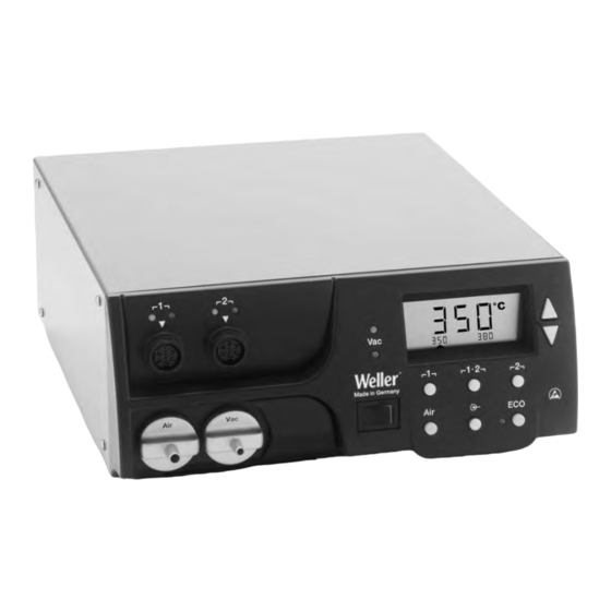
WR 2 WR 2 Présentation de l'appareil LED choix du canal LED contrôle optique de régulation LED vide Ecran Touche UP Touche DOWN Touches sélection canal / température ┌ 1 ┐, ┌ 2 ┐ LED affichage d'état 10 Touche spéciale 11 Touche de température ┌...
  • Page 43 1 A propos de cette notice Nous vous remercions de la confiance que vous nous avez témoignée en achetant le Weller WR 2. Les exigences les plus strictes en matière de qualité ont été prises en compte lors de sa fabrication et vous garantissent un fonctionnement irréprochable de...
  • Page 44 4-22 WR 2 2 Pour votre sécurité La station de réparation WR 2 a été fabriquée conformément à l'état actuel de la technique et aux règles techniques reconnues en matière de sécurité. Malgré tout, il en résulte un risque pour les personnes et le matériel si vous ne respectez pas les consignes de sécurité...
  • Page 45 WR 2 5-22 4 Description de l'appareil La station Weller WR 2 est une station de réparation polyvalente destinée aux opérations de réparation professionnelles sur des groupes électroniques de technologie ultra moderne dans le secteur technique de la fabrication industrielle, ainsi que dans le domaine de la réparation et des laboratoires.
  • Page 46 6-22 WR 2 Caractéristiques techniques WR 2 Dimensions L x l x H (mm) : 273 x 235 x 102 L x l x H (pouces) : 10,75 x 9,25 x 4,02 Poids Env. 6,7 kg Tension de réseau 230 V, 50 Hz (120 V, 60 Hz) Puissance absorbée 300 W Degré...
  • Page 47 WR 2 7-22 5 Mise en service de l'appareil Risque de blessures par mauvais raccordement du AVERTISSEMENT ! flexible à vide. Si le flexible à vide n'est pas raccordé correctement, de l'air chaud et de l'alliage à base d'étain liquide peuvent émerger lors de l'actionnement du fer à...
  • Page 48 8-22 WR 2 6 Utilisation de l'appareil Sélection, activation ou désactivation d'un canal 1. Appuyer sur l'une des touches ┌ 1 ┐ ou ┌ 2 ┐ (7) pour sélectionner l'un des deux canaux. L'écran affiche la température de consigne du canal sélectionné ainsi qu'en petits caractères les températures programmées fixes.
  • Page 49 WR 2 9-22 Réglage de température avec les touches de température ┌ 1 ┐, ┌ 1·2 ┐ et ┌ 2 ┐ La température de consigne peut être réglée individuellement pour chaque canal en sélectionnant trois valeurs de température préréglées (températures fixes). Réglages d'usine: ┌...
  • Page 50 10-22 WR 2 Soudage et dessoudage  Effectuez les opérations de soudage conformément à la notice d'utilisation de votre outil de soudage raccordé. 7 Fonctions spéciales Les fonctions spéciales sont réparties sur 2 niveaux de menus : 2 s ➾ Menu 1 ...
  • Page 51 WR 2 11-22 Réinitialisation des fonctions spéciales par rapport aux réglages usine 1. Appuyer sur la touche ┌ 2 ┐ et la maintenir enfoncée. 2. Presser ensuite simultanément les touches UP et DOWN. L'écran affiche “FSE”. La station de réparation est à présent à nouveau réinitialisée par rapport aux réglages usine.
  • Page 52 12-22 WR 2 Réglage du temps de coupure automatique (AUTO-OFF) Lorsque l'outil de soudage n'est pas utilisé, le chauffage de l'outil de soudage est coupé au bout du temps AUTO-OFF. La coupure de la température s'effectue indépendamment de la fonction "Setback" réglée.
  • Page 53 WR 2 13-22 Comportement de la température pour les différents réglages des fonctions SETBACK et AUTO OFF Réglages Comportement de la température sans plaque reposoir commutatrice SETBACK OFF Time Time [1-99 min] [1-999 min] L'outil à souder reste à la température de soudage réglée. L'outil de soudage se coupe lorsqu'il n'est pas utilisé...
  • Page 54 14-22 WR 2 Réglage du décalage de température La température réelle de la panne à souder peut être adaptée en entrant un décalage (offset) de température de ± 40 °C (± 70 °F). 1. Sélectionner l'option OFFSET dans le menu 1. 2.
  • Page 55 WR 2 15-22 Réglage de la temporisation au déclenchement du vide (VAC Off) Afin d'empêcher le colmatage de la panne à dessouder, il est possible de régler une temporisation de coupure du vide entre 0 et 5 secondes (réglage usine 2 secondes). 1.
  • Page 56 16-22 WR 2 Sélection des fonctions spéciales menu 2 Fonctions spéciales Navigation ↑ LEVEL ┌ 1 ┐ ↓ ┌1·2┐ AUTO CHANNEL SP BUTTON EXIT ┌ 2 ┐ changement HAP LOCK canal HI / LO CONTROL 1. Sélectionner le canal souhaité ┌ 1 ┐, ┌1·2 ┐ ou ┌ 2 ┐ pour l'entrée des fonctions spéciales.
  • Page 57 WR 2 17-22 Utilisation de la fonction de calibrage (Factory Calibration Check) La fonction FCC vous permet de contrôler la précision de température de la station de réparation et de compenser d'éventuelles déviations. A cet égard, la température de la panne à souder doit être mesurée à...
  • Page 58 18-22 WR 2 Nota Presser la touche ┌ 2 ┐ pour quitter l'option de menu sans modifications (EXIT). 6. Appuyer sur la touche ┌1·2 ┐ (Set) pour valider la valeur. La différence de température est à présent réinitialisée sur 0. Le calibrage à...
  • Page 59 WR 2 19-22 Activation / Désactivation du verrouillage des touches HAP Cette fonction permet de modifier le comportement des touches du fer HAP tel qu'il a été réglé en usine. Si le verrouillage est activé, le fer HAP s'allume à la première pression sur la touche et s'éteint à la pression suivante.
  • Page 60 45° vers la gauche et le retirer. 2. Retirer le filtre encrassé et le rebuter dans les règles de l'art. 3. Monter une cartouche filtrante WELLER d'origine. Faire ici attention au positionnement correct du joint de couvercle. 4. Monter le ressort de pression.
  • Page 61 WR 2 21-22 11 Accessoires T005 29 200 99 WP 200 Kit de soudage avec support WDH 31, 200 W T005 29 194 99 WP 120 Kit de soudage avec support WDH 10T, 120 W T005 29 193 99 WP 120 Fer à souder, 120 W T005 29 181 99 WP 80 Kit fer à...
  • Page 62 écrite de notre part sous réserve de l'emploi du terme "Garantie". Sous réserve de modifications techniques! Vous trouverez les notices d'utilisation mises à jour sur le site www.weller-tools.com.
  • Page 63 WR 2 – Circuit Diagram...
  • Page 64 WR 2 – Exploded Drawing...
  • Page 65 GERMANY GERMANY GREAT BRITAIN GREAT BRITAIN GERMANY GERMANY GREAT BRITAIN GREAT BRITAIN Weller Weller Tools Tools GmbH GmbH Apex Tool Apex Tool Group Group Weller Weller Tools Tools GmbH GmbH Apex Tool Apex Tool Group Group Carl-Benz-Str. 2 ( ( ( ( UK Limited...

Ce manuel est également adapté pour:

Wr 2