Quick HRC 1002 Manuel De L'utilisateur
Table des Matières
Les langues disponibles
Les langues disponibles
n a u t i c a l e q u i p m e n t e v o l u t i o n
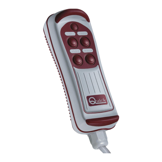
PULSANTIERA MULTIUSO
HRC 1002
HRC 1004
HRC 1006
HRC 1008
HRC 1002 L
HRC 1004 L
HRC 1006 L
HRC 1008 L
Manuale d'uso
I
User's Manual
GB
Manuel de l'utilisateur
F
Benutzerhandbuch
D
Manual del usuario
E
UP
DOWN
LEFT
RIGHT
PULSANTIERA MULTIUSO HRC
HRC MULTIPURPOSE CONTROL PANEL
BOITIER DE COMMANDE MULTI-USAGE HRC
MEHRZWECK-FERNBEDIENUNG HRC
TABLERO DE PULSADORES MULTIUSO HRC
REV 002
Table des Matières

Manuels Connexes pour Quick HRC 1002


Sommaire des Matières pour Quick HRC 1002
- Page 1 PULSANTIERA MULTIUSO HRC 1002 HRC 1004 HRC 1006 DOWN HRC 1008 LEFT RIGHT HRC 1002 L HRC 1004 L HRC 1006 L HRC 1008 L Manuale d’uso PULSANTIERA MULTIUSO HRC User’s Manual HRC MULTIPURPOSE CONTROL PANEL Manuel de l’utilisateur...
-
Page 3: Table Des Matières
INDICE Pag. 4 Caratteristiche e Installazione - Pag. 8 Installazione / Funzionamento installazione della presa - personalizzazione della pulsantiera Pag. 5 Installazione - installazione della presa - connessione alla presa Pag. 6 Installazione - Supporto Pag. 9 Funzionamento - schemi di collegamento Pag. -
Page 20: Caracteristiques Et Installation
CARACTERISTIQUES ET INSTALLATION BOITIER DE COMMANDE MULTI-USAGE Le boîtier de commande Quick ® est un instrument conçu pour actionner à distance différents systèmes mobiles à bord du bateau comme des grues, des passerelles, des échelles de bain, des guindeaux. INSTALLATION AVANT D’UTILISER L’INSTRUMENT, LIRE ATTENTIVEMENT CE MODE D’EMPLOI. - Page 21 INSTALLATION Après avoir choisi où placer l’instrument, procéder comme indiqué ci-après: • Placer le gabarit de perçage (livré avec le produit) sur la surface où sera installée la prise. • Marquer le centre de chaque trou. • Faire le trou pour le passage du câble de la prise avec un forêt. •...
-
Page 22: 22 Installation - Support
INSTALLATION INSTALLATION DU SUPPORT La procédure type du montage est décrite ci-dessous. Il est impossible de fournir une procédure standard utilisable pour toutes les situations. Il faut donc adapter cette procédure à vos exigences spécifiques. Déterminer la position la plus adéquate pour loger le support et suivre les instructions ci- dessous: •... -
Page 23: Extraction Du Boitier De Commande Du Support
INSTALLATION EXTRACTION DU BOITIER DE COMMANDE DU SUPPORT Pour extraire le boîtier de commande du support, suivre les indications présentes dans la séquence illustrée: Déboîter le boîtier de commande en le soulevant de quelques centimètres, le faire tourner dans un sens ou dans l’autre; enlever le boîtier de commande du support en le soulevant. -
Page 24: 24 Installation / Fonctionnement
INSTALLATION - FONCTIONNEMENT PERSONNALISATION DU BOITIER DE COMMANDE Sur certains modèles de HRC, la symbolique associée à chaque touche peut être changée grâce aux adhésifs en dotation. La procédure pour la personnalisation du boîtier de commande est décrite ci-après: • Nettoyer les surfaces correspondantes (fig. 1) avec un chiffon humecté d’eau. •... -
Page 25: Fonctionnement
NOIR NOIR BLANC BLANC BLANC VERT VERT VERT ROUGE ROUGE GRIS GRIS ORANGE JAUNE HRC 1002 L HRC 1004 L HRC 1006 L HRC 1008 L MARRON COMMUN MARRON COMMUN MARRON COMMUN MARRON COMMUN BLEU BLEU BLEU BLEU NOIR NOIR... - Page 26 FONCTIONNEMENT ALLUMAGE ET EXTINCTION DE LA TORCHE HRC 1002 L - HRC 1004 L - HRC 1006 L - HRC 1008 L L’allumage et l’extinction de la torche s'effectue en appuyant et en relâchant le bouton qui se trouve en haut avec le symbole de la lumière, voir fig. 3.
-
Page 27: Entretien - Caractéristiques Techniques
Surcharge résistive sous 30 Vdc. Uniquement sur les modèles HRC 1002 L - HRC 1004 L - HRC 1006 L - HRC 1008 L. Avec la fiche correctement introduite dans la prise. La zone de la prise où est soudé le câble de sortie est exclue (IP 00). - Page 44 HRC / L DIMENSIONI (mm) DIMENSIONS - DIMENSIONS - ABMESSUNGEN - MEDIDAS HRC 1002 / L HRC 1004 / L HRC 1006 / L HRC 1008 / L 62.2 49.4 DOWN LEFT RIGHT 59.1 41.6...
- Page 45 NOTE NOTES / NOTES / DIE ANMERKUNGEN / NOTAS...
- Page 46 NOTE NOTES / NOTES / DIE ANMERKUNGEN / NOTAS...
- Page 48 CMPLSHRC0R02 QUICK ® SRL - VIA PIANGIPANE , 120/A - 48020 PIANGIPANE (RAVENNA) - ITALY TEL. +39.0544.415061 - FAX +39.0544.415047 www.quickitaly.com - E-mail: quick@quickitaly.com...