Télécharger Imprimer la page
CAME BX-246 Manuel Pour L'installation

CAME BX-246 Manuel Pour L'installation

Automatisme pour portails coulissants
Masquer les pouces Voir aussi pour BX-246:

Publicité

Les langues disponibles

Les langues disponibles

Liens rapides

1 1 9B U5 0 IT
1 1 9B U50
IT
Italiano
EN
English
FR
Français
RU
Русский
AUTOMAZIONI
PER CANCELLI SCORREVOLI
MANUALE D'INSTALLAZIONE
BX-246
IT
Italiano

Publicité

loading

Sommaire des Matières pour CAME BX-246

  • Page 1 AUTOMAZIONI 1 1 9B U5 0 IT 1 1 9B U50 PER CANCELLI SCORREVOLI Italiano English Français Русский MANUALE D’INSTALLAZIONE BX-246 Italiano...
  • Page 2 • Il prodotto deve essere destinato solo all’uso per il quale è stato espres- o altri prodotti chimici che potrebbero rovinare i dispositivi) • Nel caso si samente studiato. Ogni altro uso è da considerarsi pericoloso. CAME Can- rendano necessarie riparazioni o modifi che alle regolazioni dell’impianto, celli Automatici S.p.A non è...
  • Page 3 Per uso intensivo o condominiale: peso massimo del cancello 600 kg con lunghezza massima 18 m. 3 Riferimenti normativi Came Cancelli Automatici è una azienda certificata per il sistema di gestione della qualità aziendale ISO 9001 e di gestione ambientale ISO 14001. Came progetta e produce interamente in Italia.
  • Page 4 4.3 Descrizione delle parti Coperchio superiore Carter copriregolazioni Supporto per scheda elettronica Alette fi necorsa Scheda elettronica ZD2 Coperchio anteriore quadro elettrico Sportello di accesso per sblocco motoriduttore Piastra di fissaggio Vite di fissaggio 10. Scontro per viti di fissaggio 11.
  • Page 5 5.2 Attrezzi e materiali Assicurarsi di avere tutti gli strumenti e il materiale necessario per effettuare l’installazione nella massima sicurezza e secondo le normative vigenti. In figura alcuni esempi di attrezzatura per l’installatore. 5.3 Tipo cavi e spessori minimi Lunghezza cavo Lung.
  • Page 6 5.5 Fissaggio piastra e posa del gruppo Le seguenti illustrazioni sono solo esempi, in quanto lo spazio per il fissaggio dell’automazione e degli accessori varia a seconda degli ingombri. Spetta quindi all’installatore scegliere la soluzione più adatta. - Scavare una buca all’estremità del cancello (vedi quote dal disegno). Predisporre i tubi corrugati necessari per i collegamenti provenienti dal pozzetto di derivazione.
  • Page 7 - Per il posizionamento della piastra rispetto alla cremagliera rispettare le misure del disegno. Riempire la cassa matta di cemento e attendere che si solidifi chi per almeno 24h. - Togliere la cassa matta, riempire di terra la buca attorno al blocco di cemento. - Svitare i dadi e le rondelle dalle viti.
  • Page 8 - Togliere il coperchio del motoriduttore svitando le viti laterali. Posizionare il motoriduttore sopra la piastra. Attenzione! I cavi elettrici devono passare all’interno della cassa del motoriduttore. - Sollevare il motoriduttore dalla base di fi ssaggio di 5÷10 mm agendo sui piedini fi lettati di acciaio per permettere le eventuali regolazioni successive tra pignone e cremagliera.
  • Page 9 - Aprire e chiudere il cancello manualmente e registrare la distanza dell’accoppiamento pignone-cremagliera attraverso i piedini fi lettati di acciaio (regolazione verticale) e le asole (regolazione orizzontale). Questo permette di evitare che il peso del cancello gravi sull’automazione. Cremagliera Cremagliera Pignone Pignone Piedini...
  • Page 10 5.6 Fissaggio alette finecorsa Posizionare le alette fi necorsa sulla cremagliera e fi ssarle con chiave esagonale da 3 mm. La loro posizione, delimita la misura della corsa. Nota: evitare che il cancello vada in battuta contro il fermo meccanico, sia in apertura che in chiusura. Fermo meccanico 5.7 Sblocco manuale del motoriduttore - Inserire la chiave trilobata nella serratura, spingerla e girarla in senso orario, ..
  • Page 11 6 Scheda elettronica 6.1 Descrizione generale La scheda elettronica va alimentata a 230V AC sui morsetti L-N, per la corsa normale sia per il rallentamento; con frequenza max 50/60Hz. - la velocità sia per la corsa normale sia per il rallentamento. I dispositivi di comando e gli accessori sono a 24V.
  • Page 12 3 4 5 6 7 8 9 10 6.3 Collegamenti elettrici Motoriduttore, finecorsa ed encoder Descrizione dei collegamenti elettrici già previsti per installazione a sinistra Nero Arancione Rosso Bianco Arancione Marrone Rosso Motore 24 V (DC) Microinterruttore Microinterruttore di con Encoder di apertura chiusura Modifiche dei collegamenti elettrici per installazione a destra...
  • Page 13 Alimentazione accessori Capocorda a occhiello con vite e rondella per collegamento a terra Morsetti per l’alimentazione degli accessori: - a 24V AC normalmente; - a 24V DC quando intervengono le batterie d’emergenza; Potenza complessiva consentita: 35W Alimentazione 230V (AC), frequenza 50/60 Hz Dispositivi di segnalazione Lampeggiatore di movimento (Portata contatto: 24V - 25W max.) - Lampeggia durante le fasi di apertura e chiusura del...
  • Page 14 Dispositivi di sicurezza Fotocellule DIR / DELTAS Contatto (N.C.) di «stop parziale» - Ingresso per dispositivi di sicurezza tipo fotocellule, conformi alle normative EN 12978. Arresto del cancello se in movimento e successiva chiusura automatica (se la funzione è stata selezionata). Fotocellule DIR / DELTAS Contatto (N.C.) di «riapertura durante la chiusura»...
  • Page 15 DF con scheda Contatto (N.C.) di «riapertura durante la di controllo dei chiusura» collegamenti DFI - Ingresso per dispositivi di sicurezza tipo bordi sensibili, conformi alle normative EN 12978. In fase di chiusura del cancello, l’apertura del contatto provoca l’inversione del movimento fi no alla completa apertura del cancello;...
  • Page 16 7 Selezioni funzioni DIP-SWITCH Settaggio di default 1 ON - Chiusura automatica - Il temporizzatore della chiusura automatica si attiva a finecorsa in apertura. Il tempo prefissato è regolabile, ed è comunque condizionato dall’eventuale intervento dei dispositivi di sicurezza e non si attiva dopo uno «stop» totale di sicurezza o in mancanza di energia elettrica.
  • Page 17 9 Led di segnalazione Led PROG Led PWR Led 1 Led C8 Led 3p Led 7 Led C1 Led C3 Led C7 ELENCO DI SEGNALAZIONE DEI LED DI CONTROLLO DEI DISPOSITIVI DI COMANDO E SICUREZZA: - «PROG» Led di colore rosso. Normalmente spento. Durante la procedura di attivazione del trasmettitore, si accende o lampeggia.
  • Page 18 10 Programmazione per memorizzare la taratura corsa e i rallentamenti Eseguire la taratura della corsa facendo compiere all’automazione una manovra completa di apertura e una di chiusura. La scheda elettronica registra automaticamente la taratura della corsa con i rallentamenti di apertura e chiusura. Memorizzare la taratura posizionando il dip 6 in ON e premere il tasto CH1 fino a quando il led di segnalazione rimane acceso.
  • Page 19 11 Attivazione del comando radio Collegare il cavo RG58 dell’antenna. Togliere la tensione e, se presenti, scollegare le batterie. Inserire la scheda AF sulla scheda elettronica. La scheda elettronica riconosce la scheda AF solo quando viene ridata tensione all’automazione. Tenere premuto il tasto CH1 sulla scheda elettronica: il LED di segnalazione lampeggia. Premere un tasto del trasmettitore per inviare il codice: il LED rimarrà...
  • Page 20 12 Collegamento di due motoriduttori abbinati con comando unico Con due motoriduttori abbinati, è possibile comandare solo l’apertura (con pulsante e/o radiocomando): il cancello si richiuderà solo con la chiusura automatica. • Coordinare il senso di marcia dei motoriduttori e , modifi cando la rotazione del motore (invertire i cavi sui morsetti FA-FC e M-N).
  • Page 21 13 Indicazioni di sicurezza Importanti indicazioni generali di sicurezza Questo prodotto deve essere destinato solo all’uso per il quale è stato espressamente studiato. Ogni altro uso è da considerarsi impro- prio e quindi pericoloso. Il costruttore non può essere considerato responsabile per eventuali danni causati da usi impropri, erronei ed irragionevoli.
  • Page 22 Registro manutenzione periodico a cura dell’utente (ogni 6 mesi) Data Annotazioni Firma 14.2 Risoluzione dei problemi DISFUNZIONI POSSIBILI CAUSE VERIFICHE E RIMEDI Il cancello non • Manca alimentazione • Verificare la presenza di rete apre e non chiude • Il motoriduttore è sbloccato •...
  • Page 23 UNI EN ISO 14001 a garanzia del rispetto e della tutela dell’ambiente. Vi chiediamo di continuare l’opera di tutela dell’ambiente, che CAME considera uno dei fondamenti di sviluppo delle proprie strategie operative e di mercato, semplicemente osservando brevi indicazioni in materia di smaltimento: SMALTIMENTO DELL’IMBALLO...
  • Page 24 HR • Za sve dodatne informacije o poduzeću, proizvodima i tehničkoj podršci: UK • Для отримання будь-якої іншої інформації про компанію, продукцію та технічну підтримку: www. came.com www. came.com CAME Cancelli Automatici S.p.a. CAME Cancelli Automatici S.p.a. Via Martiri Della Libertà, 15 31030 Dosson Di Casier...
  • Page 25 AUTOMATION 1 1 9 BU 50 EN FOR SLIDING GATES INSTALLATION MANUAL BX-246 English...
  • Page 26 • This product should only be used for the purpose for which it was instructions • If the power cable is damaged, it must be replaced by the explicitly designed. Any other use is considered dangerous. CAME Cancelli manufacturer or the technical assistance service or by a person with a Automatici S.p.A.
  • Page 27 For intensive or condominium use: max gate weight 600kg with max gate length 18 m. 3 Reference standards The company CAME cancelli automatici is ISO 9001 quality certified; it has also obtained the ISO 14001 environmental safeguarding certification. CAME engineers and manufactures all of its products in Italy.
  • Page 28 4.3 Description of parts 1 - Top cover 2 - Settings casing 3 - Control board support 4 - Endstop fins 5 - ZD2 electronic card 6 - Front cover to control panel 7 - Gearmotor release door 8 - Securing plate 9 - Securing bolt 10 - Securing screw plate 11 - Nut...
  • Page 29 5.2 Tools and materials Make sure you have all the tools and materials you will need for the installation at hand to work in total safety and compliance with the current standards and regulations. The following figure illustrates the minimum equipment needed by the installer. 5.3 Cable list and minimum thickness Length of cable Length of cable...
  • Page 30 5.5 Securing the plate and installing the assembly The following applications are only examples, as the space for installing the ratiomotor and accessories varies according to obstructions. It is thus up to the system installer to select the most suitable solution. - Dig a pit to the side of the gate (see measurements from diagram).
  • Page 31 - To position the plate in relation to the rack please see the measurements on the diagram. Fill the form box with cement and wait for at least 24 hours for it to solidify. - Remove the form box, fi ll the pit around the cement block with soil. - Unbolt the nuts and washers from the bolts.
  • Page 32 - Remove the cover from the gearmotor by loosening the side bolts, perforate the cable shafts using a screwdriver or a pair of scissors and position the gearmotor atop the plate. Careful! The electric cables must pass through the cable shafts. - Lift the gearmotor from the securing plate by about 5 to 10mm by using the threaded steel-levelling feet to allow any later adjustments between the pinion and the rack.
  • Page 33 - Open and close the gate manually and register the pinion-to-rack distance using the threaded steel-levelling feet (for vertical adjusting) and the slotted holes (horizontal adjusting). This prevents the weight of the gate from bearing on the operator. Rack Rack Pinion Pinion Levelling feet...
  • Page 34 5.6 Mounting the endstop fins Place the endstop fi ns onto the rack and secure them using a 3 mm Allen wrench. Their positioning limits the gate run. Note: the gate schould not slam against the mechanical stop, when opening or closing. Mechanical stop 5.7 Manually releasing the gearmotor - Insert the trilobed key into the lock, push it in and turn it clockwise ..
  • Page 35 6 Control board 6.1 General description Use 230V AC to power the electronic card using the L-N - The automatic closing’s running time; terminals, at a max 50/60Hz frequency. - The partial opening; - The amperometric device’s detection sensitivity, in both normal Use 24V to power the command devices and accessories.
  • Page 36 3 4 5 6 7 8 9 10 6.3 Electrical connections Gearmotor, endstop and encoder Description of the standard electrical connections for left-hand installations Black Orange White Orange 24 V (DC) motor Opening microswitch Closing microswitch with encoder Modifications to the electrical connections for right-hand installations White Invert the gearmotor (U-V) and (FA-FC) endstop phases.
  • Page 37 Power supply for accessories Cable lug with bolt and washer for connecting to earth. Terminals for powering the following accessories: - 24V AC normally; - 24V DC when the emergency batteries are working; Maximum allowed power: 35W 230V (AC) Power, 50/60Hz frequency Warning devices Movement fl...
  • Page 38 Safety devices DIR / DELTAS photocells «partial stop» (N.C.) contact - Input for EN 12978 standard-compliant safety devices such as photocells. Gate stops if moving and automatically shuts (if this functions has been selected). DIR / DELTAS photocells (N.C.) contact for «re-open during closing phase» - Input for EN 12978 standard-compliant safety devices such as photocells.
  • Page 39 DF with DFI con- «Open while closing»(N.C.) contact nections monitor - input for EN 12978 compliant safety card devices such as sensitive edges. During gate closing, opening the contact causes inversion of movement until gate is fully open; if not used, short circuit contact 2-C7.
  • Page 40 7 Function selector DIP-SWITCH Default Setting 1 ON - Automatic Closing - The automatic closing timer activates at the end of the opening gate run. The pre-set time is adjustable, and is in any case conditioned by the activation of any safety devices, and does not activate after a total safety “stop” or during a blackout.
  • Page 41 9 Warning Led Led PROG Led PWR Led 1 Led C8 Led 3p Led 7 Led C1 Led C3 Led C7 LIST WARNINGS OF THE COMMAND AND SAFETY DEVICES’ CONTROL LEDs: - «PROG» Red Led. Normally off . When the transmitter is activating, it turns on or fl ashes. - «PWR»...
  • Page 42 10 Programmation to save gate-run and decelerations adjustments Do the adjustment by making the operator execute a complete opening/closing manoeuvre The control board automatically registers the gate-run adjustments with opening and closing decelerations. To save the adjustment, position dip 6 in ON and press CH1 button until the signalling led stays on. Re-position the dip in OFF Lit LED DIP 6 to OFF...
  • Page 43 11 Activating the radio control Connect the antenna’s RG58 cable. Cut off the main power supply, and remove any batteries. Fit the AF board onto the electronic board. The electronic board recognizes the AF board only when the operator is powered up again. Keep the CH1 button on the electronic board pressed: the warning LED flashes.
  • Page 44 12 Connecting two coupled gearmotors having a single control With two coupled gearmotors, you can command only the opening (by button and/or radio control): the gate will close only in automatic closing mode. • Coordinate the direction of travel of the two gearmotors and , by modifying the motor's rotation (invert the cables on terminals FA-FC and M-N).
  • Page 45 13 Safety instructions Important safety instructions This product must only be employed for its originally intended use. Any other use is wrong and potentially dangerous. The manufactu- rer cannot be held liable for any damages resulting from wrongful, erroneous or negligent uses. Avoid working close to the hinges or other moving mechanical parts.
  • Page 46 Periodic maintenance log for end-user (every 6 moths) Signature Date Notes 14.2 Trouble shooting MALFUNCTIONS POSSIBLE CAUSES CHECK AND REMEDIES The gate will not • There is no power • Check that the power is up open nor close • The gearmotor is in release mode and the release door is open •...
  • Page 47 CAME CANCELLI AUTOMATICI S.p.A. employs a UNI EN ISO 14001 certified and compliant environmental protection system at its plants, to ensure that environmental safeguarding. We ask you to keep protecting the environment, as CAME deems it to be one of the fundamental points of its market operations strategies, by simply following these brief guidelines when disposing: DISPOSING THE PACKING MATERIALS The packing components (cardboard, plastic, etc.) are solid urban waste and may be disposed of without any particular difficulty, by simply...
  • Page 48 HR • Za sve dodatne informacije o poduzeću, proizvodima i tehničkoj podršci: UK • Для отримання будь-якої іншої інформації про компанію, продукцію та технічну підтримку: www. came.com www. came.com CAME Cancelli Automatici S.p.a. CAME Cancelli Automatici S.p.a. Via Martiri Della Libertà, 15 31030 Dosson Di Casier...
  • Page 49 AUTOMATISME 11 9 B U5 0F R POUR PORTAILS COULISSANTS MANUEL POUR L’INSTALLATION BX-246 Français...
  • Page 50 Toute autre utilisation est à considérer comme fonctionnement des photocellules et des bords sensibles tous les six mois. dangereuse. La société CAME Cancelli Automatici S.p.A. décline toute Pour s'assurer du bon fonctionnement des photocellules, y passer devant responsabilité en cas d'éventuels dommages provoqués par des utilisations un objet durant la fermeture ;...
  • Page 51 Pour usage intensif ou dans des copropriétés: poids maximum du portail 600 kg. avec une longueur maximum de 18 m. 3 Normes de référence CAME cancelli automatici est une entreprise certifiée par le Système de Contrôle Qualité des Entreprises ISO 9001 et de Gestion de l’Environnement ISO 14001. Les produits CAME sont entièrement conçus et fabriqués en Italie.
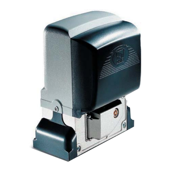
  • Page 52 4.3 Description des éléments 1 - Couvercle supérieur 2 - Carter de protection des réglages 3 - Support pour carte 4 - Aliette de butée fi n de course 5 - Carte électronique ZD2 6 - Couvercle antérieur armoire de commande 7 - Volet d’accès pour déverrouillage moto- réducteur 8 - Plaque de fixage...
  • Page 53 5.2 Outils et matériel Assurez-vous d’avoir tous les outils et le matériel nécessaire pour effectuer le montage de l’automatisme en toute sécurité et confor- mément aux normes en vigueur. Sur la planche, quelques exemples de matériel pour l’installateur. 5.3 Types de cables et epaisseurs minimales Longueur câble Longueur câble Longueur câble...
  • Page 54 5.5 Fixage plaque et pose du groupe Les applications suivantes ne sont que des exemples, étant donné que l’espace pour le fixage de l’automatisme et de ses accessoires varie selon les encombrements. C’est l’installateur qui devra choisir la solution la plus appropriée. - Creusez un trou à...
  • Page 55 Respectez les mesures du dessin pour placer la plaque par rapport à la crémaillère. Remplissez la caisse de béton et attendez au moins 24 h. pour qu’il se solidifi e. - Prélevez la caisse, remplissez le trou de terre autour du bloc de béton. - Dévissez les écrous et les rondelles des vis.
  • Page 56 - Prélevez le couvercle du motoréducteur en dévissant les vis latérales, trouez les passe-câbles avec un tournevis ou des ciseaux et placez le motoréducteur sur la plaque. Attention! Les câbles électriques doivent passer dans les passe-câbles. - Soulevez de 5÷10 mm. le motoréducteur de la base de fi xage en utilisant les pieds taraudés en acier pour permettre éventuellement les réglages entre le pignon et la crémaillère.
  • Page 57 - Ouvrez et fermez manuellement le portail, réglez la distance du couplage pignon-crémaillère à travers les pieds taraudés en acier (réglage vertical) et les fentes (réglage horizontal). Cela permet d’éviter à l’automatisme de devoir supporter la charge du poids du portail.
  • Page 58 5.6 Fixage ailetettes butée fin de course Placez les ailettes de butée fi n de course sur la crémaillère et fi xez-les avec une clé hexogonale de 3 mm. Leur position détermine la misure de la course. N.B.: il faut éviter que le portail heurte l’arrêt mécanique, aussi bien en ouverture qu’en fermeture. Arrêt mécanique 5.7 Déverrouillage manuel du moto-réducteur - Introduisez la clé...
  • Page 59 6 Carte électronique 6.1 Description générale La carte électronique doit être alimentée en 230V AC sur les - l’ouverture partielle ; borniers L-N, avec fréquence max.50/60Hz. - La sensibilité de détection du dispositif ampérométrique, aussi bien pour la course normale que pour le ralentissement ; Les dispositifs de commande et les dispositifs accessoires sont en 24V.
  • Page 60 3 4 5 6 7 8 9 10 6.3 Connexions électriques Motoréducteur, butée de fin de course et encodeur Description des connexions électriques déjà prévues pour installation à gauche Noir Orange Rouge Blanc Orange Rouge Moteur 24 V (DC) Micro interrupteur Micro interrupteur avec Encodeur d’ouverture...
  • Page 61 Alimentation accessoires Cosse de câble à œillet avec vis et rondelle pour connexion à terre Borniers pour l’alimentation des accessoires : - en 24V AC normalement ; - en 24V DC quand les batteries de secours interviennent ; Puissance globale autorisée : 35W Alimentation en 230V (AC), fréquence 50/60 Hz Dispositifs de signalisation...
  • Page 62 Dispositifs de sécurité Photocellules DIR / DELTAS Contact (N.C.) de «stop partiel» - Entrée pour dispositifs de sécurité type photocellules, conformes aux normatives EN 12978. Arrêt du portail s’il est en mouvement et successivement fermeture automatique (si la fonction a été sélectionnée). Photocellules DIR / DELTAS Contact (N.C.) de «réouverture pendant la fermeture»...
  • Page 63 DF avec carte Contact (N.C.) de «réouverture de contrôle des pendant la fermeture» connexions DFI - Entrée pour dispositifs de sécurité type bords sensibles, conformes aux normatives EN 12978. Au cours de l’étape de fermeture du portail, l’ouverture du contact déclenche l’inversion du mouvement jusqu’à...
  • Page 64 7 Sélections fonctions DIP-SWITCH Confi guration de défaut 1 ON - Fermeture automatique - Le temporisateur de la fermeture automatique se met en marche en fin de course en ouverture. La durée préétablie est réglable, toutefois elle est conditionnée par l’intervention éventuelle des dispositifs de sécurité et ne fonctionne pas après un «...
  • Page 65 9 Led de signalisation Led PROG Led PWR Led 1 Led C8 Led 3p Led 7 Led C1 Led C3 Led C7 LISTE DE SIGNALISATION DES LEDS DE CONTROLE DES DISPOSITIFS DE COMMANDE ET DE SECURITE : - «PROG» Led de couleur rouge. Normalement éteinte. Pendant l’opération de mise en service de l’émetteur, elle s’allume ou clignote.
  • Page 66 10 Programmation pour mettre en mémoire le calibrage de la course et des ralentissements Effectuez le calibrage de la course en faisant faire à l’automatisme une manœuvre complète d’ouverture ainsi qu’une de fermeture. La carte électronique enregistre automatiquement le calibrage de la course avec les ralentissements d’ouverture et de fermeture. Mettez en mémoire le calibrage en plaçant le dip 6 sur ON et appuyez sur la touche CH1 jusqu’à...
  • Page 67 11 Activation de la commande radio Connecter le câble RG58 de l’antenne. Mettre hors tension et déconnecter les éventuelles batteries. Insérer la carte AF sur la carte électronique. La carte électronique ne reconnaît la carte AF qu’à la remise sous tension de l’automatisme. Maintenir la touche CH1 enfoncée sur la carte électronique : le voyant de signalisation clignote.
  • Page 68 12 Connexion de deux motoréducteurs accouplés à commande unique Avec deux motoréducteurs accouplés, il est possible de commander uniquement l'ouverture (par bouton et/ou radiocommande) : le portail ne se refermera qu'à la fermeture automatique. • Coordonner le sens de marche des motoréducteurs et en modifi ant la rotation du moteur (inverser les câbles sur les bornes FA-FC et M-N).
  • Page 69 13 Consignes pour la sécurité Consignes générales importantes pour la sécurité Ce produit doit être utilisé seulement pour le service pour lequel il a été spécialement conçu. Toute autre utilisation sera considérée impropre et donc dangereuse. Le constructeur décline sa responsabilité pour les dommages éventuellement causés par des utilisations inexactes, incorrectes et irrationnelles.
  • Page 70 Registre de maintenance périodique à la charge de l’usager (tous les 6 mois) Date Remarques Signature 14.2 Résolution des problèmes MAUVAIS FONCTIONNEMENT CAUSES POSSIBLES CONTRÔLES ET SOLUTIONS Le portail ne s’ouvre pas et il • Il n’y a pas d’alimentation •...
  • Page 71 UNI EN ISO 14001 pour garantir le respect et la sauvegarde de l’environnement. L’usager est prié de continuer cet effort de sauvegarde de l’environnement que Came considère comme un des facteurs de développement de ses stratégies de fabrication et commerciales, en suivant ces brèves indications concernant le recyclage: ÉLIMINATION DE L’EMBALLAGE...
  • Page 72 HR • Za sve dodatne informacije o poduzeću, proizvodima i tehničkoj podršci: UK • Для отримання будь-якої іншої інформації про компанію, продукцію та технічну підтримку: www. came.com www. came.com CAME Cancelli Automatici S.p.a. CAME Cancelli Automatici S.p.a. Via Martiri Della Libertà, 15 31030 Dosson Di Casier...
  • Page 73 1 1 9 B U 50 RU АВТОМАТИКА ДЛЯ ОТКАТНЫХ ВОРОТ ИНСТРУКЦИЯ ПО МОНТАЖУ BX-246 Русский...
  • Page 74 значению. Любое другое применение рассматривается как опасное. тов, проведите перед ними предметом во время закрывания ворот. CAME Cancelli Automatici S.p.A. снимает с себя всякую ответствен- Если створка меняет направление движения или останавливается, ность за возможный ущерб, нанесенный в результате неправильного...
  • Page 75 Настоящее изделие соответствует требованиям следующих стандартов: смотрите заявление о соответствии. 4. Описание 4.1 Автоматика Это изделие разработано и изготовлено компанией CAME CANCELLI AUTOMATICI S.p.A в полном соответствии с действующими нормами безопасности. Корпус, защищающий электромеханический самоблокирующийся мотор-редуктор, изготовлен из алюминиевого сплава. Под...
  • Page 76 4.3 Основные компоненты 1 - Кожух привода 2 - Заглушки крепления привода 3 - Шасси крепления платы 4 - Упоры концевых выключателей 5 - Плата блока управления ZD2 6 - Крышка платы блока управления 7 - Дверца для доступа к системе разблокировки...
  • Page 77 5.2 Инструменты и материалы Перед началом монтажных работ убедитесь в наличии всех необходимых инструментов и материалов, которые позволят произвести установку системы в полном соответствии с действующими нормами безопасности. На рисунке представлен минимальный набор инструментов, необходимых для проведения монтажных работ. 5.3 Тип и сечение кабелей Длина...
  • Page 78 5.5 Крепление монтажного основания и сборка привода Приведенные ниже рисунки носят иллюстративный характер, так как пространство для крепления автоматики и дополнительных устройств может меняться от случая к случаю. Таким образом, выбор наиболее подходящего решения должен осуществляться установщиком на месте. - Выройте яму (смотрите размеры на рисунке). Проложите...
  • Page 79 - Выровняйте монтажное основание относительно фундамента: см. размеры на рисунке. Заполните опалубку цементным раствором и оставьте не менее чем на 24 часа чтобы он полностью затвердел. - Вытащите опалубку, засыпьте пространство вокруг цементного блока землей. - Отвинтите гайки и снимите шайбы с винтов. Монтажное основание должно быть чистым и абсолютно ровным, резьба винтов должна...
  • Page 80 - Снимите верхнюю крышку привода, отвернув боковые саморезы. Установите привод на монтажное основание. Внимание! Электрические кабели должны проходить через подготовленные отверстия. - Приподнимите привод над монтажным основанием на 5÷10 мм, используйте стальные регулировочные шпильки, чтобы позднее произвести регулировку зазора между шестерней и зубчатой рейкой. - Приведенные...
  • Page 81 - Откройте и закройте ворота вручную и отрегулируйте расстояние от шестерни до зубчатой рейки, используя шпильки с резьбой (для вертикальной настройки) и овальные отверстия ( для горизонтальной настройки). Это позволит избежать излишнего давления массы ворот на привод. Зубчатая рейка Зубчатая рейка Шестерня...
  • Page 82 5.6 Установка упоров концевых выключателей Установите и закрепите упоры концевых выключателей на зубчатой рейке с помощью шестигранного ключа 3 мм. Выбор позиции определяется ограничениями движения ворот. Внимание! Ворота не должны упираться в механические упоры в конечных точках движения. Механический упор 5.7 Ручная...
  • Page 83 6. Блок управления 6.1 Техническое описание Электропитание платы блока управления ~230 В подается Благодаря соответствующей регулировке можно установить: на контакты L-N, с частотой 50/60 Гц. - время срабатывания режима автоматического закрывания; - частичное открывание; Для электропитания устройств управления и аксессуаров - чувствительность...
  • Page 84 3 4 5 6 7 8 9 10 6.3 Электрические подключения Привод, концевые выключатели и энкодер Описание электрических подключений, уже предусмотренных при установке привода слева относительно проезда, если смотреть изнутри Черный Оранжевый Красный Белый Оранжевый Красный Привод =24 В с Концевой...
  • Page 85 Электропитание и аксессуары Провод с болтом и шайбой должен быть подключен к контакту заземления Клеммы для питания дополнительных устройств: - ~24 В в стандартных условиях; - =24 В, когда работают аккумуляторы аварийного питания; Макс. допустимая суммарная мощность: 35 Вт Напряжение питания ~230 В, частота...
  • Page 86 Устройства безопасности Фотоэлементы DIR / DELTAS "Частичный стоп" (НЗ) - Вход для устройств безопасности, например, фотоэлементов, соответствующих требованиям стандарта EN 12978. Остановка ворот, если они находятся в движении, с последующим автоматическим закрыванием (если эта функция установлена). Фотоэлементы DIR / DELTAS "Открывание...
  • Page 87 DF с платой "Открывание в режиме закрывания" управления (НЗ) подключениями DFI - Вход для устройств безопасности, в частности, чувствительных профилей, соответствующих требованиям стандарта EN 12978. Размыкание контакта во время закрывания створок приводит к изменению направления их движения до полного открывания ворот.
  • Page 88 7. Выбор режимов работы и функций DIP-SWITCH Исходные установки 1 ON - Автоматическое закрывание - Таймер автоматического закрывания включается в момент полного открывания ворот. Время регулируется. Таймер сбрасывается при активации систем безопасности и отключается при нажатии кнопки "Стоп" или отключении электропитания. 2 ON - Функция...
  • Page 89 9. Светодиодные индикаторы Led PROG Led PWR Led 1 Led C8 Led 3p Led 7 Led C1 Led C3 Led C7 ПЕРЕЧЕНЬ КОНТРОЛЬНЫХ СВЕТОДИОДНЫХ ИНДИКАТОРОВ УСТРОЙСТВ УПРАВЛЕНИЯ И БЕЗОПАСНОСТИ: - «PROG» Красный светодиодный индикатор. Обычно выключен. Загорается или мигает в процессе активирования брелока-передатчика. - «PWR»...
  • Page 90 10. Программирование конечных положений и точек замедления Выполните настройку привода, активировав полный рабочий цикл автоматики: открывание ворот и закрывание. Ворота откроются и закроются с замедлением, электронная плата автоматически запомнит крайние положения. Сохраните регулировку, установив микропереключатель 6 в положение ON и нажмите на кнопку CH1 до тех пор, пока светодиодный...
  • Page 91 11. Активация радиоуправления Подключите кабель RG58 антенны к соответствующим контактам. Отключите электропитание и отсоедините аккумуляторы при их наличии. Вставьте плату AF в разъем платы блока управления. Прежде чем вставить плату радиоприемника AF в разъем блока управления, ОБЯЗАТЕЛЬНО отключите электропитание, поскольку блок управления распознает новое устройство только в момент подачи на него напряжения. Нажмите...
  • Page 92 12 Подключение двух приводов для синхронной работы При подключении двух приводов для синхронной работы можно отдавать только команду "Открыть ворота" (с помощью кнопки управления и/или брелока-передатчика): ворота будут закрываться автоматически. • Скоординируйте направление движения приводов и , изменив направление вращения привода (поменяйте местами провода...
  • Page 93 13. Инструкции по технике безопасности Важные инструкции по технике безопасности Это изделие должно использоваться исключительно по назначению. Любое другое применение, не предусмотренное в данной инструкции, рассматривается как опасное. Фирма-изготовитель не несет никакой ответственности за ущерб, нанесенный неправильным использованием системы. Избегайте контакта с направляющими скобами с роликами или другими подвижными механизмами системы во избежание травм.
  • Page 94 Журнал периодического технического обслуживания, заполняемый пользователем (каждые 6 месяцев) Дата Заметки Подпись 14.2 Устранение неисправностей НЕПОЛАДКИ ВОЗМОЖНЫЕ ПРИЧИНЫ СПОСОБ УСТРАНЕНИЯ Створка ворот не • Нет напряжения питания. • Проверьте наличие сетевого двигается. • Разблокирован привод. электропитания. • Разрядились батарейки брелока-передатчика. •...
  • Page 95 ______________________________________________________________________________________ ______________________________________________________________________________________ 15. Утилизация отходов В качестве гарантии защиты и охраны окружающей среды компания CAME CANCELLI AUTOMATICI S.p.A внедряет на территории своих учреждений систему управления окружающей средой, сертифицированную и полностью соответствующую международному стандарту UNI EN ISO 14001. Мы просим, чтобы Вы продолжали защищать окружающую среду. САМЕ считает одним из фундаментальных пунктов стратегии...
  • Page 96 HR • Za sve dodatne informacije o poduzeću, proizvodima i tehničkoj podršci: UK • Для отримання будь-якої іншої інформації про компанію, продукцію та технічну підтримку: www. came.com www. came.com CAME Cancelli Automatici S.p.a. CAME Cancelli Automatici S.p.a. Via Martiri Della Libertà, 15 31030 Dosson Di Casier...