Best IC34 Instructions
Table des Matières
Les langues disponibles
Les langues disponibles
Liens rapides
In USA - BEST Hartford, Wisconsin
In CANADA - BEST Drummondville, QC, Canada
REGISTER YOUR PRODUCT ONLINE AT : www.BestRangeHoods.com/register
For additional Information visit www.BestRangeHoods.com
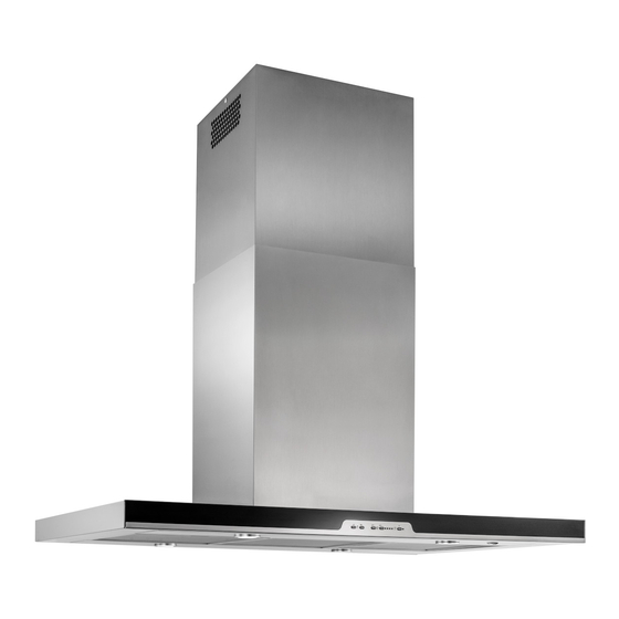
Model IC34
ENGLISH........................................3
FRANÇAIS...................................23
ESPAÑOL.....................................45
Table des Matières

Manuels Connexes pour Best IC34


Sommaire des Matières pour Best IC34
- Page 22 - 22 -...
- Page 23 Modèle IC34 ENGLISH........3 FRANÇAIS........23 ESPAÑOL........45 Aux États-Unis - BEST Hartford, Wisconsin Au CANADA - BEST Drummondville, QC, Canada ENREGISTREZ VOTRE PRODUIT EN LIGNE À : www.BestRangeHoods.com/register Pour de plus amples informations, visitez www.BestRangeHoods.com - 23 -...
- Page 24 - 24 -...
-
Page 25: Instructions De Mise À La Terre
LIRE CES DIRECTIVES ET LES CONSERVER CONÇUE POUR LES CUISINES PRIVÉES UNIQUEMENT AVERTISSEMENTS POUR RÉDUIRE LES RISQUES D’INCENDIE, D’ÉLECTROCUTION OU DE BLESSURES PHYSIQUES, RESPECTEZ LES INSTRUCTIONS CI-DESSOU: 1. Utilisez cet appareil uniquement de la manière prévue par le fabricant. Si vous avez des ques- tions, contactez le fabricant à... -
Page 26: Avertissements
12. MODÈLES VENTILATEUR EXTERNE SEULEMENT: Pour réduire les risques d’incendie ou de choc électrique, installez cette hotte uniquement avec les modèles de ventilateur extérieur Best EB6, EB9, EB12 ou EB15, ou les modèles de ventilateur intermédiaire BestILB3, ILB6, ILB9 ou ILB11. -
Page 27: Nettoyage Et Entretien
NETTOYAGE ET ENTRETIEN Pour assurer les performances de l'appareil, entretenez-le de manière appropriée. Moteur Le moteur est lubrifié en permanence et aucun graissage n'est nécessaire. Si les roulements du moteur font un bruit excessif ou inhabituel, remplacez le moteur par une pièce de rechange identique. -
Page 28: Fonctionnement
FONCTIONNEMENT COMMANDES (Fig.1) La hotte fonctionne à l’aide de (5) boutons-poussoirs situés sur la face avant. L’interrupteur d’Éclairage Marche/Arrêt allume et éteint les lumières. Le bouton de Ventilateur Arrêt / - réduit la vitesse du ventilateur à chaque pression. Si l’on maintient le bouton enfoncé... -
Page 29: Préparation De La Hotte
PRÉPARATION DE LA HOTTE Déballez la hotte et vérifiez le contenu de l’emballage. Il doit comprendre : 1 - Hotte 1 - De carneau décoratif 1 - Structure de support 1 - Sac de pièces (B080811002) contenant: 32 - Vis de montage (à tête cylindrique de 3,9 x 9,5 mm) 6 - Vis de montage (6 x 60mm) 10 - Rondelles ø... -
Page 30: Installation Du Systeme D'evacuation
ATTENTION: Pour réduire les risques d’incendie et électrique, installer cette hotte seulement avec un ventilateur extérieur Best Modèles EB6, EB9, EB12 ou EB15, et les ventilateur en ligne Best Modèles ILB3, ILB6, ILB9 ou ILB11 uniquement. On ne peut pas utiliser d’autres ventilateurs (les ventilateurs sont vendus séparément). -
Page 31: Installer Les Conduits Ipb9Iq
VENTILATEUR IN-LINE FIG. 5 INSTALLER LES CONDUITS COUVERCLE DU TOIT IPB9IQ TUYAU ROND DE 8” REMARQUE: pour réduire les risques d’incendie, utilisez uniquement des conduits métalliques. 1. Décidez où le tuyau doit être installé, entre COUDE votre hotte et l’extérieur. ROND DE 8”... - Page 32 INSTALLATION DU SYSTEME CLOISON SÈCHE CADRE CROISÉ DE SUPPORT ” 1. Installez, à l’emplacement de votre hotte, un cadre croisé de 2 x 4 entre les solives du plafond en suivant les dimensions qui vous sont indiquées. SOLIVES DU PLAFOND 2.
-
Page 33: Installation De La Hotte
INSTALLATION DE LA HOTTE VIS D’ASSEMBLAGE 3,9x9,5mm HOTTES CANALISÉES CANALISÉES 1. Enlevez le boîtier électrique du cadre de la cheminée en retirant (2) vis de 3,9 x 9,5 mm. (Fig. 8). 2. Fixer la plaque elctrical avec 4 vis (3.9x9.5mm) à la hotte, les vis se trouvent à l’intérieur du sachet accessoires (Fig. -
Page 34: Installation Du Conduit Decoratif
5. Réglez la hauteur totale de la structure de support. Désserrez et resserrez les 4 vis dans les fissures permettant de régler la hauteur selon ce qui est nécessaire. . Insérez 16 vis (3.9x9.5mm), et 8 rondelles (D.4.3) situés dans le paquet de matériel (Fig. -
Page 35: Installation Hotte Non Canalisée Uniquement
INSTALLATION HOTTE NON CANALISÉE UNIQUEMENT Remarque: a. Veuillez vous procurer l’ensemble de recirculation sans conduits, modèle ANKWC345. b. Les pièces ayant un plafond de 305 cm (10 pi) ou 335 cm (11pi) nécessitent la rallonge de conduit décoratif modèle AEIC34SBN, offerte chez votre marchand local. -
Page 36: Installation Electrique
INSTALLATION ELECTRIQUE (IC34IQ) Remarque: Ce modèle de hotte doit être relié à la terre correctement. Cet article devrait être installé par un électricien qualifié selon les lois nationales et locales en matière d’électricité. 1. Enlevez le couvercle de la boîte de COUVERCLE DE connexion électrique. -
Page 37: Installation Des Filtres
INSTALLATION DES FILTRES HOTTES CANALISÉE ET NON CANALISÉE REMARQUE : Avant l’utilisation, enlevez la pellicule protectrice sur le cadre du filtre. 1. Enlevez le filtre à GRAISSES en tirant la languette du loquet vers le bas pour dégager le filtre de la hotte. Inclinez le filtre vers le bas et enlevez-le (Fig.22). -
Page 38: Calibrage Du Ventilateur Iq
CALIBRAGE DU VENTILATEUR IQ VENTILATEUR INTERNE AVEC CONDUITS SEULEMENT Une fois la hotte installée et connectée, enclenchez le processus de calibrage (notre Technologie de performance garantie s’assure que le débit d’air optimal sera émis). Avant le calibrage, assurez-vous que les filtres, les ampoules d’éclairage et les conduits sont installés. CALIBRAGE Maintenez le bouton de calibrage pendant 3 secondes;... - Page 39 IC34E Mode de Programmation Procédure FIG. 24 - 39 -...
-
Page 40: Garantie
GARANTIE LIMITéE DE UN AN DE BEST Broan-NuTone LLC (Broan-NuTone) garantit à l'acheteur original que les produits BEST vendus en vertu de la présente sont libres de tout vice de matériau ou de fabrication pour une période de un an à compter de la date d'achat originale. CETTE GARANTIE NE COMPORTE AUCUNE AUTRE GARANTIE, EXPRESSE OU TACITE, Y COMPRIS, MAIS SANS S'Y LIMITER, LES GARANTIES TACITES DE VALEUR MARCHANDE OU D'ADAPTATION À... -
Page 41: Pièces De Rechange
PIÈCES DE RECHANGE MODÈLE IC34IQ PART N. DESCRIPTION B08087679 Filtres à graisse BE3351998 Support de Diffuseur de Lumiére B02300804 Capteur de température B06102619 Ensemble de Fils B003102891 Verre avant B032904990 Fils de passage BE3350233 Boîte de alimentation BE3334252 Couvercle Boîte de alimentation B08092904 Structure de Support Inférieure B08093457... - Page 42 - 42 -...
- Page 43 PIÈCES DE RECHANGE MODÈLE IC34E PART N. DESCRIPTION B08087679 Filtres à graisse B02300804 Capteur de température B06102628 Ensemble de Fils B003102891 Verre avant B032904990 Fils de passage BE3350233 Boîte de alimentation BE3334252 Couvercle Boîte de alimentation B08092904 Structure de Support Inférieure B08093457 Structure de Support Supérieure B08092983...
- Page 44 - 44 -...
- Page 46 - 46 -...
- Page 66 - 66 -...
- Page 67 - 67 -...
- Page 68 04308401/3 99045181C...