Télécharger Imprimer la page

Publicité

Les langues disponibles

Les langues disponibles

Liens rapides

All manuals and user guides at all-guides.com
# 160700
www.ikarus.net
160700-0203
Bauanleitung
Building Instruction
Notice de Montage
Rumpler Taube

Publicité

loading

Sommaire des Matières pour iKarus Rumpler Taube

  • Page 1 All manuals and user guides at all-guides.com # 160700 www.ikarus.net 160700-0203 Bauanleitung Building Instruction Notice de Montage Rumpler Taube...
  • Page 2 Die einfache Montage anhand der folgenden Montage-anleitung ist in kürzester Zeit durchgeführt. Sie benötigen nur wenig Werkzeug und etwas Sekundenkleber, Schaum-kleber (z.B. Uhu-Por) und lösungsmittelfreien Expoxyd-kleber. Lieferumfang Rumpler Taube Zubehör (nicht im Lieferumfang enthalten) Microregler Nr. 160533 Verwenden Sie eine handelsübliche 2-3 Kanal-Fernsteuerungsanlage, Micro-servos und Miniempfänger.
  • Page 3 All manuals and user guides at all-guides.com 1) Verkleben Sie mit Schaumkleber die Rumpfrippen mit dem Rumpfhauptspant und kleben Sie die zwei Balsaholzstreifen in die seitlichen Aussparungen. Balsaholzstreifen Spant Rippen 2) Kleben Sie mit Sekundenkleber die zwei Balsaholz-klötzchen (95x10x10 und 45x10x10) an einem Ende bündig übereinander.
  • Page 4 All manuals and user guides at all-guides.com Klebeband Rumpfschalen Ruderklappe Leitwerk 30°-Fase 5) Leitwerke Schleifen Sie eine Fase von ca. 30° an die Ruderklappen. Befestigen Sie die Klappen dann mit dem beigefügten Kle-beband so am Leitwerk, daß sich die Klappen ca. +/- 30° bewegen lassen. 6) Stecken Sie nun wie abgebildet Ruderhörner durch die Ruderklappen und befestigen Sie sie mit Schaum- bzw.
  • Page 5 All manuals and user guides at all-guides.com 8) Schleifen Sie an die Flächenendkante (Unterseite) Flächenend- eine Fase bis auf eine Stärke kanten von ca. 3mm . Bestreichen Sie d i e K l e b e k a n t e n m i t Schaumkleber und lassen Sie diese ab-lüften.
  • Page 6 All manuals and user guides at all-guides.com 10) Fahrwerk In der Mitte der Räder befindet sich eine Markierung. Dort stechen Sie ein Loch (z.B. Stricknadel) mit ca 3-4 mm Durchmesser. Bohren Sie für die Fahrwerksdrähte in die Radnaben je ein Loch mit 1,6mm Durchmesser. Kleben Sie die Radnaben dann mit lösungsmittelfreiem Epoxydkleber beidseitig Bohren ein.
  • Page 7 All manuals and user guides at all-guides.com 15) Kleben Sie die zwei Rumpfrippen bündig zusammen (Schaumkleber) und kleben Sie sie wie gezeigt zur Hälfte ein. Die überstehende Rumpfrippe wird später in die Flügelaufnahme eingerastet. Rumpfrippen 16) Schneiden Sie am vorderen Teil des Rumpfrückens eine Flügelaufnahme Aussparung für die Flügelbefestigungsschraube (ca.
  • Page 8 All manuals and user guides at all-guides.com 17) Gemäß beigefügter Schablone schneiden Sie eine Öffnung in die Rumpfnase zum Einbau des Motors. 18) Schneiden Sie mit einer Schere die Fahrwerks-befestigungslaschen (4St.) aus dem ABS-Material heraus. Befestigen Sie mit den beigefügten Schrauben das Fahrgestell auf den Fahrwerkauflagebrettchen. Stecken Sie die Räder durch die Radachsen und sichern sie mit den Stellringen (1,5mm).
  • Page 9 All manuals and user guides at all-guides.com Seitenleitwerk Motoraufhängung 20) Löten Sie den Drehzahlsteller an den Motor (gemäß Beschreibung). Kleben Sie mit Sekundenkleber den Motorsockel mit montiertem Getriebe und Motor auf die Motoraufhängung. 21) Montieren Sie die Servos in den Rumpfspannt. Be- achten Sie, daß...
  • Page 10 All manuals and user guides at all-guides.com 24) Schrauben Sie die Löthülsen bis zur Hälfte in die Gabelköpfe ein. Rasten Sie die Gabelköpfe in den Servoruderhörnern ein und stellen Sie die Leitwerksflossen gerade. Nun können Sie die erforderliche Länge der Schubstangen erkennen und entsprechend kürzen.Kleben Sie den Kohlestab mit Sekundenkleber in die Löthülse.
  • Page 11 All manuals and user guides at all-guides.com Hinweise zum Flug. Fliegen Sie nur an windstillen Tagen , in der Halle, in einem Saal oder vergleichbaren Orten oder bei leichtem Wind. Kontrollieren Sie vor dem Flug den sicheren Sitz aller Komponenten und den Schwerpunkt.
  • Page 12 All manuals and user guides at all-guides.com The Rumpler Taube shows a totally new concept. The durability and stiffnes of the light weight fuselage is the result of the construction as a monocoque. The new aerodynamic definition of the Taube is responsible for a very easy handling. Experience a truly special kind of flying.
  • Page 13 All manuals and user guides at all-guides.com 1.) Attach the formers to the fuselage main former and mount the two Balsa strips in the according position. (use styrofoam glue) Balsa strips former formers 2.) Glue the two Balsa blocks (95 x 10 x 10 mm and 45 x 10 x 10 mm) together, lining up one end. (use CA glue) This part is the front wing and the motor carrier.
  • Page 14 All manuals and user guides at all-guides.com monocoques selfadhesive tape fin/stabilisator rudder/elevator bevel 30 degree Tail wings 5.) Cut or sand a 30 degree bevel in the rudder/elevator of the tailplane. When this is done attach them using adhesive tape to hinge the surface as shown. 6.) Cut holes in elevator and rudder ( ¼...
  • Page 15 All manuals and user guides at all-guides.com Sand the wings trailing edge Tail edge of (bottom side) to a thickness of 3 mm (1/8 in.). Apply styrofoam the wing glue to the contact edge and let them dry a little bit. Lay the wing down on a plain surface, press the gluing edge down and attach the winglet.
  • Page 16 All manuals and user guides at all-guides.com Landing gear 10) The wheel centers are marked . There you have to drill a hole of 3-4 mm(1/8 in) In the hubs you have to drill a hole of 1.6 mm(1/16 in) Glue the hubs into the wheels, using solvent free epoxy glue.
  • Page 17 All manuals and user guides at all-guides.com 15.) Glue the two formers together and then glue them into the top fuselage. Half of it should be inside, half outside. The outside former will interconnect with the fuselage. formers 16.) Cut an opening of about 20 x 20 mm (6/8 x 6/8 in.) into the wing attachement cut-off fuselage top, to give access to the wing mounting screw.
  • Page 18 All manuals and user guides at all-guides.com 18.) Using the stencil/pattern you have to cut an opening into the fuselage nose for the motor installation. 19.) Use a pair of scissors to cut out the 4 ABS landing gear straps. Attach them with the screws (included in kit) to the plywood landing gear support strips on the fuselage bottom.
  • Page 19 All manuals and user guides at all-guides.com fin / rudder 21.) Solder the motor leads of the micro speed controller to the motor carrier motor. (follow the specific manual) Use CA glue to mount the complete motor/gear box unit to the motor carrier.
  • Page 20 Use of carbon fibre tubes as wing reinforce If you will use the Rumpler Taube preferably indoors, it is not necessary to reinforce the wings. If you want to do airbatics or fly even when it is windy, we recommend to install the tubes (included in the kit).
  • Page 21 All manuals and user guides at all-guides.com Flying instructions only on calm days or indoors. Check the centre of gravity before each flight and make sure all parts are secured properly. Switch on the transmitter and make sure that the speed switch (2-channel) is off, resp.
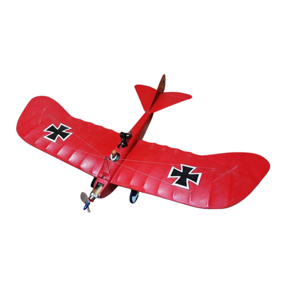
  • Page 22 All manuals and user guides at all-guides.com Notice de Montage De part sa construction, le Rumpler Taube relève d'un tout nouiveau concept. Les deux demi-coquilles qui forment le fuselage lui donne une plus grande rigidité avec un moindre poids. L'aérodynamisme du Rumpler Taube lui permet d'avoir un vol extrêmement paisible.
  • Page 23: Pièce Maîtresse Du Fuselage

    All manuals and user guides at all-guides.com 1) Collez les couples sur la pièce maîtresse du fuselage puis les deux flancs en Balsa dans les découpes de part et d'autre du fuselage. Flancs en Balsa Pièce maîtresse du fuselage Couples 2) Avec de la colle cyano, collez les deux carrés de Balsa (95 x 10 x 10 et 45 x 10 x 10) l'un sur l'autre comme le montre le vue ci-dessous.
  • Page 24 All manuals and user guides at all-guides.com Demi-coquille du fuselage bande charnière adhésive stabilisateur gouverne chanfrein de 30° 5) Empennage Poncez un chanfrein de 30° sur les gouvernes puis fixez -les sur le stabilisateur avec la bande charnière adhésive qui est fournie, en veillant à ce que les gouvernes puissent débattre de +/-30°. 6) Selon la vue ci-dessous, montez les guignols sur les gouvernes et collez-les avec de la colle polystyrène, ou mieux encore avec...
  • Page 25 All manuals and user guides at all-guides.com 8) Sur le dessous, poncez un chanfrein d'une largeur d'environ bord de fuite de l'aile 3mm. Au niveau des raccordements, déposez de la colle contact et laissez évaoporer les solvants. Posez les ailes sur un chantier bien plat, appliquez les bords des pièces de jonction bien à...
  • Page 26 All manuals and user guides at all-guides.com 10) Au centre des roues se trouve un marquage. Avec une aiguille à tricoter, par exemple, percez un trou de 3-4 mm de diamètre. Pour le passage de la corde à piano, axe de roue, percez un trou de 1,6 mm de diamètre dans les moyeux.
  • Page 27 All manuals and user guides at all-guides.com 15) Avec de la colle contact, collez deux couples l'un sur l'autre, et collez une moitié dans le fuselage comme le montre la vue ci- dessus. Le couple qui dépasse sera emboîté plus tard dans le logement de l'aile.
  • Page 28 All manuals and user guides at all-guides.com 17) A l'aide du gabarit ci-joint, découpez une ouverture dans le nez du fuselage qui permet de monter le moteur. 18) Avec un ciseau, découpez les chapeaux de roues en ABS (4 pièces). Avec les vis ci-jointes, fixez le train sur le support de train.
  • Page 29 All manuals and user guides at all-guides.com Dérive Fixation moteur 20) Soudez le variateur au moteur (selon la notice). Avec de la colle cyano, collez le support moteur avec moteur et réducteur montés sur la fixation moteur. 21) Montez les servos sur la platine. Veillez à ce que les cordons sortent vers le haut.
  • Page 30 Montage des renforts en tube carbone / Suite de la page 3 Si le Rumpler Taube évolue exclusivement en salle, il est inutile de monter les renforts en tube carbone. Si vous voulez faire un peu de voltige ou si vous volez à l'extérieur avec un peu de vent, nous vous conseillons la mise en place des tube carbone pour renforcer le modèle.
  • Page 31 Vous pouvez maintenant déployez l'antenne de votre émetteur. Pour les réglages des trims, décollez votre modèle. Mettez la gouverne de profondeur au neutre et observez le modèle. S'il chute, corrigez avec le trim jusqu'à ce que votre Rumpler Taube grimpe légèrement lorsque vous êtes plein gaz..
  • Page 32 All manuals and user guides at all-guides.com AeroFly-Professional Weltweit die Nr.1 Das gab’s sicherlich noch nie! Unglaubliche Perfektion! worldwide No. 1 A simulator like this one has not been available before! Unbelievable perfection! Fly together with a second pilot at the same time! 3-D aerobatics! De loin le Nr.
  • Page 33 •Extensive model selection (aerobatic airplanes, gliders, Equipements spéciaux slow flyers, helicopter, jets, scale aircraft, TOC models • géométrie variable •Use your own transmitter or the IKARUS Game •train rentrant Commander Controller • aérofreins, volets et volets de courbure •Change the weather parameters (wind, thermals, •...
  • Page 34 All manuals and user guides at all-guides.com Garantie: Dieses Qualitätsprodukt wurde vor dem Versand sorgfältig geprüft. Sollte es dennoch einmal einen Grund zur Beanstandung geben, so bearbeiten wir Garantieansprüche gemäß unseren aktuellen Allgemeinen Geschäfts-bedingungen. Bei Einsendung eines Gerätes, das sich nach der Eingangsprüfung als funktionsfähig herausstellt, erheben wir eine Bearbeitungsgebühr von 21.-/ 21 US-$.
  • Page 35: Prüfnummer/Inspectionnumber/Numéro Contrôle

    All manuals and user guides at all-guides.com Norbert Grüntjens Sie haben sich für den Kauf eines hochwertigen Ikarus Produktes entschieden Herzlichen Glückwunsch ! Dieses Produkt wurde auf Vollständigkeit und Korrektheit der Teile überprüft! Sollten Sie trotzdem Grund für eine Reklamation haben, so bitten wir Sie diese unter Angabe der unten aufgedruckten Nummer sowie einer Kopie des Kaufbeleges vorzunehmen! You have purchased a high-quality product from Ikarus.
  • Page 36 All manuals and user guides at all-guides.com...

Ce manuel est également adapté pour:

160700