HBM U1A Notice De Montage
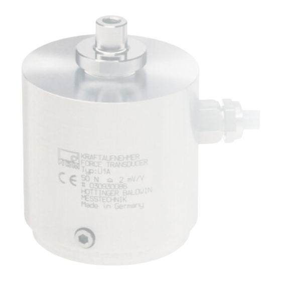
Capteur de force

Manuels Connexes pour HBM U1A


Sommaire des Matières pour HBM U1A
- Page 1 Montageanleitung Mounting instructions Notice de montage Kraftaufnehmer Force transducer Capteur de force A0279-4.0 de/en/fr...
- Page 18 a0279-4.0 de/en/fr...
- Page 34 a0279-4.0 de/en/fr...
- Page 35 Sommaire Page Consignes de sécurité ..........15 Etendue de la livraison .
-
Page 36: Consignes De Sécurité
Consignes de sécurité Utilisation conforme L’utilisation du capteur de force U1A est exclusivement réservée aux travaux de mesure et aux travaux de commande directement associés. Toute autre utilisation est considérée comme non conforme. Pour garantir un fonctionnement en toute sécurité de ce capteur, celui-ci doit être utilisé... - Page 37 Signale que des informations importantes sont fournies concernant le produit ou sa manipulation. Symbole : Signification : Label CE Avec le marquage CE, le fabricant garantit que son produit est conforme aux exigences des directives CE qui s’y appliquent (Pour voir la déclaration de conformité visitez http://www.hbm.com/HBMdoc). a0279-4.0 de/en/fr...
- Page 38 Protéger le capteur de l’humidité et des intempéries, telles que pluie, neige, etc. Entretien Le capteur de force U1A est sans entretien. Prévention des accidents Bien que la force nominale de plage de destruction donnée soit un multiple de la pleine échelle, il convient de respecter les réglements pour la prévention des accidents du travail correspondants.
-
Page 39: Etendue De La Livraison
Anneau à rotule inférieur pour taraudage M5 (tous les types) 1−U1/5kg/ZGU Application Les capteurs de force de type U1A permettent de mesurer des forces statiques et dynamiques en traction et en compression dans des machines d’essais et pour d’autres applications nécessitant d’importantes performances techniques. -
Page 40: Structure Et Principe De Mesure
Perçage pour anneau à rotule inférieur : M5 le boîtier Fig. 3.3 : Vue en coupe du U1A Le capteur est muni d’une protection contre les surcharges qui agit dans le sens de traction et de compression à partir de 150 % environ de la force introduite. -
Page 41: Pression Extérieure
18.1.2 Pression extérieure Le capteur n’est pas sensible aux modifications de la pression extérieure. 18.1.3 Dépôts Le capteur doit rester propre. Tous les dépôts qui limitent la rotation du disque de charge créent une dérivation de force et altèrent ainsi le résultat de la mesure. -
Page 42: Montage
18.2 Montage 18.2.1 Consignes générales de montage Il existe 3 variantes d’introduction de force : • Introduction de force Code A : axe (pour charge en compression,charge en traction uniquement avec accouplement) • Introduction de force Code B : filetage (pour charge en traction ou en compression) •... -
Page 43: Montage Pour Charge En Traction
18.2.3 Montage pour charge en traction Pour introduire des forces de traction, vous disposez de deux anneaux à rotule : − anneau à rotule supérieur pour accouplement M3 (opcion A) 1−U1/5kg/ZGO − anneau à rotule supérieur pour taraudage M5 (opcion C) 1−U1/5kg/ZGU −... - Page 44 Veiller à ne pas endommager le taraudage en aluminium ! ATTENTION Cet échange des pièces d’introduction de force n’est possible qu’à partir des numéros de pièces K−U1A. Pour les versions plus anciennes, le changement des pièces d’introduction de force doit être effectué chez HBM.
-
Page 45: Raccordement Électrique
En effet, les deux fils de capteur supplémentaires, gris et vert, prélèvent la tension au niveau de la boîte de jonction du capteur U1A et la ramènent à l’amplificateur de mesure. Ce dernier régule la tension de manière à ce qu’elle soit présentée au capteur sans aucune perte. - Page 46 Respecter les consignes suivantes lors de l’installation du câble : • N’utiliser que des câbles de mesure blindés et à faible capacité (les câbles HBM remplissent ces conditions). • Ne pas poser les câbles de mesure parallèlement à des lignes à grande intensité...
-
Page 47: Caractéristiques Techniques
Caractéristiques techniques Type Classe de précision Force nominale Sensibilité nominale mV/V Ecart de sensibilité rel. Différence de sensibilité traction/ compression relative Déviation relative du zéro Hystérésis rel. (0,2F à F 0,15 écart de linéarité Effet de température sur la sensibilité/10 K rapporté... -
Page 48: Dimensions
∅ 45 ∅ 49,5 longeur de 6 m env. 65 s.p.19 Variante A Variante B Variante C Cote non tolérancée selon DIN ISO 7168 - mK Fig. 7.5 : Dimensions du capteur U1A et des anneaux à rotule a0279-4.0 de/en/fr... - Page 49 Fig. 7.6 : Dimensions des anneaux à rotule a0279-4.0 de/en/fr...
- Page 50 a0279-4.0 de/en/fr...
- Page 52 Elles n’établissent aucune assurance formelle au terme de la loi et n’engagent pas notre responsabilité. Hottinger Baldwin Messtechnik GmbH Postfach 10 01 51, D-64201 Darmstadt Im Tiefen See 45, D-64293 Darmstadt Tel.: 06151 803-0; Fax: 06151 8039100 A0279-4.0 de/en/fr Email: support@hbm.com Internet: www.hbm.com...