Regin OPTIGO OP5U Mode D'emploi
Masquer les pouces
Voir aussi pour OPTIGO OP5U:
- Mode d'emploi (14 pages) ,
- Mode d'emploi (6 pages) ,
- Manuel (31 pages)
Table des Matières
Les langues disponibles
Les langues disponibles
Liens rapides
INSTRUCTION
EN
OPTIGO OP5U
i
Read this instruction before installation
and wiring of the product
Consult documentation in all cases where this symbol
is used, in order to find out the nature of the potential
hazards and any actions to be taken
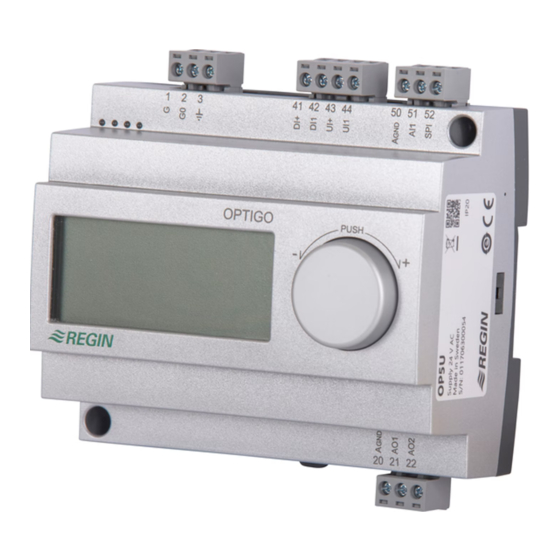
Controller with display
Optigo OP5U is a pre-programmed, configurable controller. It has 5
inputs/outputs and can be configured to control temperature, CO
humidity or pressure. All configuration and normal handling is done
using the display and the knob on the front. From revision R18, it is
possible to connect an external PT1000 setpoint device.
Technical data
Supply voltage
24 V AC ±15%, 50/60 Hz
Power consumption
3 VA
Ambient temperature
0...50°C
Ambient humidity
Max. 90% RH
Storage temperature
-20...70°C
Display
Numeric / graphic. Background
illumination.
Inputs/outputs
Refer to connection illustrations and
table below
Terminal blocks
Disconnectable, so-called lift type for
cable cross-section max 2.5 mm
Protection class
IP20
Material, casing
Polycarbonate, PC
Weight
215 g incl. terminal blocks
Dimensions
122 x 120 x 64 mm (WxHxD incl. terminals,
fixed installation)
Pollution degree
2
Temperature settings
Temperature, supply air
-20..+60, 20...100, 60...140°C
Setpoints
-18...+60, 22...100, 62...140°C
External setpoint
0...40°C
Neutral zone
0...10°C
P-band
0...99°C
I-time
0...990 s
Min. limit damper
0...99
Other settings
Setpoint values
CO
0...100% of max set value on UI1
2
General (GEN)
0...100% of max set value on UI1
Pressure (Pa)
0...100% of max set value on UI1
Scaling of UI1
0...10 V DC in
CO
10...9900 ppm
2
General
0...100%
Pressure
100 Pa...2500 kPa
Neutral zone
12.5% of max
P-band
CO
0...100% of UI1
2
General (RH)
0...100% of UI1
,
Pressure (Pa)
0...300% of UI1
2
I-time
0...990 s
Control setting 5
Outdoor compens. start
-20...+60°C
Setpoint pressure at
-20°C outdoor temp.
0 Pa...2500 kPa
OPTIGO OP5U
Installation
OP5U must be mounted in a DIN-standard casing (minimum 7
modules) or in a cabinet, either on a DIN-rail or, using the two screw-
2
pockets provided, by being screwed to any suitable flat surface in the
cabinet. The controller can also be mounted in a cabinet door or other
control panel, using a suitable front-mounting kit.
The controller must be connected to a 24 V AC safety insulating
transformer providing mains insulation.
Follow table 1 below for connection.
Table 1. I/O connection terminals. Terminals 2, 20 and 50 are internally con-
nected.
Terminal
Designation
1
G
2
G0
3
20
AGnd
21
AO1
22
AO2
41
DI+
42
DI1
43
UI+
44
UI1
50
AGnd
51
AI1
52
SPI
Digital inputs DI and UI are only intended to be used with
a potential-free contact or switch. If the Optigo OP5U and active
sensors and actuators connected to it share transformer, it is
essential that the same transformer-pole is used as reference for
all the equipment. Failure to do so will prevent the equipment from
functioning as intended and may also lead to damages.
For best protection against disturbances, a shielded twisted-pair cable
should be used for wiring the sensors. Ground the shield at one end.
The protection provided by the equipment may be impaired by im-
proper use.
Operation
Supply voltage 24 V AC
Ref. for AO1 and AO2
0...10 V DC Output
0...10 V DC Output
Reference for DI1
Digital input
Reference for UI1 digital mode
0...10 V DC or Digital input
Ref. for AI1 and UI1 analogue
PT1000 temp. sensor input
Input PT1000 setpoint device
1
Table des Matières

Manuels Connexes pour Regin OPTIGO OP5U


Sommaire des Matières pour Regin OPTIGO OP5U
-
Page 8: Caractéristiques Techniques
Régulateur avec écran Les entrées digitales DI et UI ne doivent être raccordées qu’à 0...100% de UI1 des contacts libres de potentiel. Si l’Optigo OP5U, les sondes et Général (HR) 0...100% de UI1 autres organes de commande associés (actionneurs) sont alimentés Optigo OP5U est un régulateur préprogrammé... -
Page 9: Régulation Négative, Action Inverse
(-20...+60°C). Le signal AO1 inversé est reçu de AO2. régulant le signal des sorties AO1 et AO2. AO1 est utilisé pour la régulation positive, AO2 pour la régulation négative. Une seule OPTIGO OP5U... -
Page 10: Consigne Externe
OFF pour un point de consigne interne. Avec le point de consigne externe, vous ne pouvez voir la valeur actuelle de la con- Voir le manuel «Optigo OP5U - Manuel» pour en savoir plus sur les signe que dans le menu de réglage des consignes. Lorsqu’un appa- menus de configuration.