Télécharger Imprimer la page

Publicité

Les langues disponibles

Les langues disponibles

Liens rapides

Instruction Manual September 2003
English
Deutsch
Español
Français
the probe
LEVEL MONITOR

Publicité

loading

Sommaire des Matières pour Siemens Milltronics 7ML1201-1FE00

  • Page 1 Instruction Manual September 2003 English Deutsch Español Français the probe LEVEL MONITOR...
  • Page 2 Contact SMPI Technical Publications at the following address: Technical Publications Siemens Milltronics Process Instruments Inc. 1954 Technology Drive, P.O. Box 4225 Peterborough, Ontario, Canada, K9J 7B1 Email: techpubs@siemens-milltronics.com For the library of SMPI instruction manuals, visit our Web site: www.siemens-milltronics.com © Siemens Milltronics Process Instruments Inc. 2003...
  • Page 3 Introduction Note: The Probe is to be used only in the manner outlined in this instruction manual. The Probe is an ultrasonic level monitor combining sensor and electronics in a single package. It is designed to measure liquid levels in closed vessels. The sensor is PVDF or ETFE, allowing The Probe to be used in a wide variety of industries.
  • Page 4 Threaded hinged lid 7 mm The Probe is available in three thread types: 84 mm (0.3") (3.3") max. 2" NPT, 2" BSP or PF2. 117 mm (4.6F") Note: Before inserting The Probe into its cable entry mounting hole, ensure that the threads are of ’knock out’...
  • Page 5 Interconnection Notes: • Installation shall only be performed by qualified personnel and in accordance with local governing regulations. • Separate cables and conduits may be required to conform to standard instrumentation wiring practices, or electrical codes. A. With lid closed, remove cable entry ’knock out’ on either side as required.
  • Page 6 Calibration The calibration of the mA output may be done such that its span will be either proportional or inversely proportional to the material level. Note: The 4 and 20 mA levels may be calibrated in any order. proportional span inversely proportional span high level = 20mA high level = 4 mA...
  • Page 7 Adjustments There are several operating adjustments that can be made to The Probe. • Press the "4" and "20" keys simultaneously until the desired adjustment is obtained. A viewing sequence of the stored value is automatically initiated. • During this time, press either the "4" or "20" key to change the value. After viewing or changing, operation automatically reverts to the Run mode (6 sec).
  • Page 8 Blanking The Probe Blanking is used to ignore the zone in front of the transducer where false echoes are at a level that blanking interfere with the processing of the true echo. It is measured outward from the sensor face. The minimum recommended blanking value is 0.25 m (0.82 ft) but can be increased in order to extend the blanking.
  • Page 9 • To change the speed of response, obtain the `SP' display. • Scroll forward through the options (1-2-3) by pressing the "20" key. Scroll backward through the options (3-2-1) by pressing the "4" key. • When the desired option is displayed, stop pressing the key. The display will automatically return to the Run mode (6 sec).
  • Page 10 • To change the fail-safe default obtain the `FLS' display. • Scroll forward through the options (1-2-3) by pressing the "20" key. Scroll backward through the options (3-2-1) by pressing the "4" key. • When the desired option is displayed, stop pressing the key. The display will automatically return to the Run mode (6 sec).
  • Page 11 Supplement Loading vs. Supply Voltage Troubleshooting The echo is not reliable and The Probe is waiting for a valid echo before updating the measurement. Probable causes are: • material or object in contact with sensor face • The Probe is too close to the fill point •...
  • Page 12 Specifications Power: • 18 to 30 V DC, 0.2 A max Environmental: • location: indoor / outdoor • altitude: 2000 m max. • ambient continuous:- 40 to 60 °C (-40 to 140 °F) temperature -20 °C (-5 °F) if metal mounting •...
  • Page 13 Construction: • combined sensor and electronics package • sensor housing: material: PVDF or ETFE mounting: threaded: 2”NPT, 2" BSP PF2 flanged: flange adapter, threaded Probe to 3" ANSI, DIN 65PN10 and JIS 10K3B sanitary: 4" FDA approved sanitary ferrule with integral sealing ring c/w 304 stainless steel clamp (5 m model only) •...
  • Page 14 Page 12 The Probe – INSTRUCTION MANUAL 7ML19981GD61...
  • Page 15 Einleitung Hinweis: Der Probe darf nur gemäß den Anweisungen in dieser Betriebsanleitung verwendet werden. Der Probe ist ein kompaktes Ultraschall-Füllstandmessgerät, das einen Sensor und eine Auswerteelektronik umfasst. Er wurde speziell für die Messung von Flüssigkeiten in geschlossenen Behältern entwickelt. Der Sensorteil besteht aus PVDF oder ETFE für den Einsatz in verschiedensten Industriebereichen.
  • Page 16 Gewinde Klappdeckel 7 mm Der Probe ist in drei Gewindeausführungen 84 mm (0.3") (3.3") max. erhältlich: 117 mm (4.6F") 2" NPT, 2" BSP oder PF2. Blind- Hinweis: Um eine Beschädigung des verschluss Elektronik 279 mm (11") Probe-Gewindes zu vermeiden, ist vor 87 mm Einschrauben des Probe das Montage- (3.4") ø...
  • Page 17 Anschluss Hinweis: • Die Installation darf nur durch qualifiziertes Personal und unter Beachtung der örtlichen Bestimmungen durchgeführt werden. • Unter Umständen sind Kabel und Leitungen getrennt zu verlegen, um geltenden Anschlussrichtlinien und elektrischen Normen zu genügen. A. Bei geschlossenem Deckel den vorgesehenen Blindverschluss nach Bedarf entfernen.
  • Page 18 Kalibrierung Der mA Ausgang kann so kalibriert werden, dass die Mess-Spanne proportional zum Füllstand oder zum Abstand ist. Hinweis: Die Werte für 4 und 20 mA können in beliebiger Reihenfolge kalibriert werden. proportional zum Füllstand umgekehrt proportional zum Füllstand Max. Füllstand = 20mA Max.
  • Page 19 Einstellungen Der Probe erlaubt verschiedene Parametereinstellungen. • Drücken Sie die Tasten "4" und "20" gleichzeitig, bis der gewünschte Parameter erreicht ist. Der gespeicherte Wert wird automatisch angezeigt. • Während dieser Zeit kann der Wert mit der Taste "4" oder "20" verändert werden. Nach der Anzeige oder Änderung wird automatisch wieder der Run Modus gestartet (6 Sek.).
  • Page 20 Nahbereichsausblendung The Probe Mit der Nahbereichsausblendung kann ein Bereich ignoriert werden, in dem Störechos die Auswertung des Ausblendung Nutzechos behindern. Dieser Bereich wird von der Sensorsendefläche aus gemessen. Es wird empfohlen, die Ausblendung auf mindestens 0,25 m (0,82 ft) einzustellen. Bei Bedarf kann dieser Wert erhöht werden.
  • Page 21 • Um die Reaktionszeit zu ändern, ist die 'SP' Anzeige aufzurufen. • Mit der Taste "20" können die Optionen (1-2-3) durchlaufen werden. Um die Optionen rückwärts zu durchlaufen (3-2-1), wird die Taste "4" gedrückt. • Drücken Sie die jeweilige Taste solange, bis die gewünschte Option erscheint. Die Anzeige kehrt automatisch wieder in den Run Modus zurück (6 Sek.).
  • Page 22 • Um die Failsafe-Funktion zu ändern, ist die 'FLS' Anzeige aufzurufen. • Mit der Taste "20" können die Optionen (1-2-3) durchlaufen werden. Um die Optionen rückwärts zu durchlaufen (3-2-1), wird die Taste "4" gedrückt. • Drücken Sie die jeweilige Taste solange, bis die gewünschte Option erscheint. Die Anzeige kehrt automatisch wieder in den Run Modus zurück (6 Sek.).
  • Page 23 Anhang Bürde / Versorgungsspannung Fehlersuche Das Echo ist nicht zuverlässig. Der Probe wartet auf ein auswertbares Echo, bevor der Messwert aktualisiert wird. Mögliche Ursachen: • Material (oder Zielobjekt) hat Kontakt zum Sensor • Der Probe ist zu nahe an der Befüllung angebracht •...
  • Page 24 Technische Daten Hilfsenergie: • 18 bis 30 V DC, max. 0,2 A Umgebung: • Montage: innen / im Freien • Höhe: max. 2000 m • Umgebungs- kontinuierlich: - 40 bis 60°C (-40 bis 140°F) temperatur: -20°C (-5°F) bei Montage auf Metallteilen •...
  • Page 25 Bauart: • Kompaktgerät (Sensor und Elektronik integriert) • Sensorgehäuse: Material: PVDF oder ETFE Montage: Gewinde: 2”NPT, 2" BSP PF2 Flansch: Flanschadapter, Probe mit Gewinde für 3" ANSI, DIN 65PN10 und JIS 10K3B Sanitär: 4" FDA Tri-Clamp mit gussgekapseltem Ring und Klemmschelle aus Edelstahl 304 (nur 5 m modell) •...
  • Page 26 Seite 12 The Probe – BETRIEBSANLEITUNG 7ML19981GD61...
  • Page 27 Introducción Nota: The Probe debe ser utilizado únicamente de la manera que se especifica en este manual. The Probe es un transmisor de nivel ultrasónico que combina un sensor y una parte electrónica en un cuerpo único. Está diseñado para medir niveles de líquidos en depósitos abiertos o cerrados. El sensor se fabrica en Kynar PVDF o ETFE lo que lo hace adecuado para una amplia variedad de industrias.
  • Page 28 Con rosca Tapa abatible 7 mm The Probe está disponible con tres tipos de rosca: 84 mm (0,3") (3,3") máx. 2" NPT, 2" BSP ó PF2. 117 mm (4,6F") Nota: Antes de instalar The Probe, Entrada de asegurarse de que la rosca sea del mismo cable Electrónica 279 mm...
  • Page 29 Conexiones Notas: • Sólo el personal cualificado está autorizado a intervenir en este equipo para la instalación. El producto debe ser utilizado de la manera que se especifica en este manual. • Pueden ser necesarios cables y conductos separados para cumplir las habituales normas de cableado de instrumentación o normas eléctricas.
  • Page 30 Calibración La calibración de la salida mA puede efectuarse de forma que la distancia total (span) sea proporcional o inversamente proporcional al nivel de material. Nota: Los valores 4 y 20 mA pueden calibrarse en cualquier orden. proporcional inversamente proporcional nivel alto = 20mA nivel alto = 4 mA nivel bajo = 4 mA...
  • Page 31 Ajustes Se pueden efectuar varios ajustes para conseguir un nivel de operación óptimo de The Probe. • Pulsar simultáneamente las teclas "4" y "20" hasta visualizar el ajuste deseado. Se visualiza automáticamente el valor almacenado. • El usuario puede modificar este valor pulsando la tecla "4" ó "20". Después de la visualización o modificación, el indicador vuelve automáticamente al modo Run (6 segundos).
  • Page 32 Zona muerta The Probe La zona muerta se utiliza para ignorar la zona frente al transductor en la que los falsos ecos tienen un nivel que Zona muerta interfiere en el proceso del eco verdadero del material. Se mide partiendo de la cara del transductor, en metros. En fábrica se introduce el valor de zona muerta de 0.25 m (0,82 pies) que puede incrementarse en caso necesario.
  • Page 33 • Para cambiar la velocidad de respuesta a la medición, visualizar `SP'. • Visualizar las opciones (1-2-3). Incrementar pulsando la tecla "20". Visualizar las opciones (3-2-1) decrementar pulsando la tecla "4". • Al visualizar la opción deseada, detener la secuencia soltando la tecla. El display / indicador vuelve automáticamente al modo Run (6 segundos).
  • Page 34 • Para ajustar la autoprotección, visualizar `FLS' en el indicador. • Visualizar las opciones (1-2-3) incrementando con la tecla "20". Visualizar las opciones (3-2-1) decrementando con la tecla "4". • Al visualizar el valor deseado, soltar la tecla. El display / indicador vuelve automáticamente al modo Run (6 segundos).
  • Page 35 Suplemento Carga / tensión de alimentación Solución de fallos El eco no es fiable. The Probe espera un eco válido antes de actualizar la medición. Causas probables: • Material u objeto en contacto con la cara del transductor • The Probe está demasiado cerca del punto de llenado •...
  • Page 36 Especificaciones Alimentación eléctrica: • 18 a 30 V cc, máx. 0,2 A Condiciones ambientales: • Ubicación: interior / exterior • Altitud: máx. 2000 m • Temperatura contínua: - 40 a 60°C (-40 a 140°F) ambiente: -20°C (-5°F) con montaje metálico •...
  • Page 37 Construcción: • sensor y electrónica en un solo alojamiento • encapsulado: material: PVDF o ETFE montaje: rosca: 2”NPT, 2" BSP PF2 brida: adaptador para bridas, 3" ANSI, DIN 65PN10 y JIS 10K3B sanitario: férula sanitaria 4" certificada por la FDA, con anillo de estanqueidad intégrado y tuerca mariposa de acero inoxidable 304 (modelo de 5 m solamente) •...
  • Page 38 Página 12 The Probe – MANUAL DE INSTRUCCIONES 7ML19981GD61...
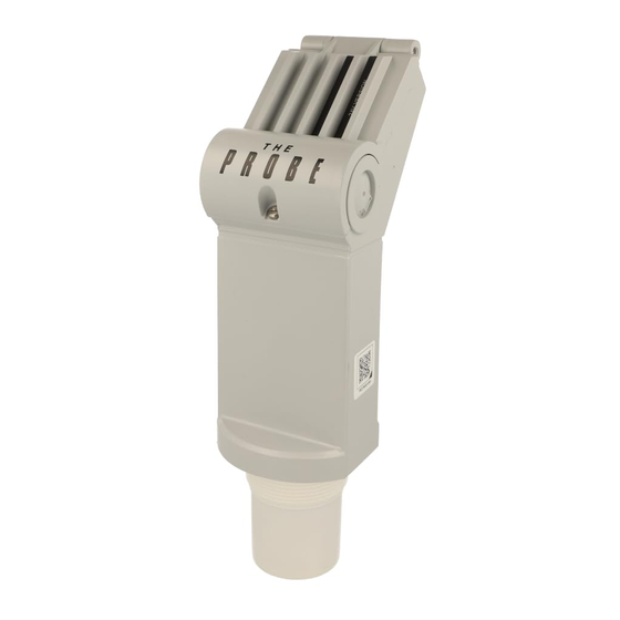
  • Page 39 Introduction Note : Le Probe doit être utilisé suivant les instructions fournies dans ce manuel. L’unité de mesure de niveau Probe intègre l’électronique et le capteur dans un seul et unique boîtier. Cette unité est destinée à la mesure de liquides, dans toutes cuves ou réservoirs fermées. Le capteur est fabriqué...
  • Page 40 Raccord fileté couvercle à charnière 7 mm L’unité est disponible en trois versions de 84 mm (0.3") (3.3") max. filetage : 2" NPT, 2" BSP ou PF2. 117 mm (4.6F") Note : Afin d’éviter d’endommager Le Probe pré-perçage lors de l’installation, vérifier que le filetage électronique 279 mm (11")
  • Page 41 Interconnexions Notes : • L’installation doit être effectuée par un personnel qualifié, en accord avec les dispositions locales en vigueur. • Il peut être nécessaire de séparer les câbles et conduits pour respecter les prescriptions particulières, consignes de câblage et normes électriques. A.
  • Page 42 Etalonnage L’étalonnage de la sortie analogique peut être réalisé de telle sorte qu’elle soit proportionnelle ou inversement proportionnelle au niveau mesuré. Note : L’étalonnage des niveaux 4 et 20 mA n’est pas soumis à un ordre particulier. proportionnelle inversement proportionnelle niveau haut = 20mA niveau haut = 4 mA niveau bas = 4 mA...
  • Page 43 Réglages Plusieurs réglages sont possibles pour optimiser le fonctionnement de l’unité Probe. • Presser les touches "4" et "20" jusqu’à obtenir le réglage souhaité. La valeur programmée est automatiquement affichée. • Pendant ce temps, la valeur peut être modifiée en pressant la touche "4" ou "20". Une fois la valeur visualisée ou modifiée, l’unité...
  • Page 44 Zone Morte La zone morte est utilisée pour masquer la zone sous le Le Probe capteur où les échos parasites sont à des niveaux zone morte pouvant interférer avec le traitement de l’écho vrai. La zone morte est mesurée vers l’extérieur à partir de la face du capteur.
  • Page 45 • Pour modifier le temps de réponse, visualiser `SP'. • Presser la touche "20" pour visualiser les options (1-2-3). Presser la touche "4" pour visualiser les options (3-2-1). • Une fois l’option souhaitée affichée, cesser de presser la touche. L’afficheur revient automatiquement en mode Run (6 secondes).
  • Page 46 • Pour modifier la valeur par défaut, visualiser `FLS'. • Presser la touche "20" pour visualiser les options (1-2-3). Presser la touche "4" pour revenir aux options (3-2-1). • Cesser de presser la touche dès que l’option souhaitée est affichée. L’affichage revient automatiquement en mode Run (6 secondes).
  • Page 47 Supplément Charge / tension d’alimentation Dépistage des défauts L’écho reçu n’est pas fiable. Le Probe attend de recevoir un écho valide avant de rafraîchir la mesure. Les causes probables sont : • Matériau ou cible en contact avec la face émettrice du capteur •...
  • Page 48 Caractéristiques Techniques Alimentation : • 18 à 30 V cc, 0.2 A maximum Caractéristiques environnementales : • montage : en intérieur / extérieur • altitude : 2000 m maximum • température continue : - 40 à +60°C (-40 à +140°F) ambiante: -20°C (-5°F) pour montage métallique •...
  • Page 49 Construction : • monobloc, incluant le capteur et l’électronique • corps du capteur : matériau : PVDF ou ETFE montage : filetage : 2”NPT, 2" BSP PF2 bride : adaptateur bride, 3" ANSI, DIN 65PN10 et JIS 10K3B sanitaire : col sanitaire 4" approuvé par la FDA avec anneau d’étanchéité...
  • Page 50 Page 12 Le Probe – MANUEL D’INSTRUCTIONS 7ML19981GD61...
  • Page 51 Siemens Milltronics Process Instruments Inc. Siemens Milltronics Process Instruments Inc. 2003 1954Technology Drive, P .O. Box 4225 Subject to change without prior notice Peterborough, ON, Canada K9J 7B1 Rev. 1.2 Tel: (705) 745-2431 Fax: (705) 741-0466 *7ml19981GD61* Email: techpubs@siemens-milltronics.com...

Ce manuel est également adapté pour:

The probe