Publicité

Les langues disponibles

Les langues disponibles

Liens rapides

Brief Operating Instructions
Ecograph T
Multi Channel Recorder RSG30
Display, record & communicate
;
Seite 2
<
Page 20
=
Page 38
KA199R/09/a3/10.08
No.: 51009566
Software
ETU00xA, V2.02.xx

Publicité

Table des Matières
loading

Sommaire des Matières pour Endress+Hauser Ecograph T RSG30

  • Page 1 Brief Operating Instructions Ecograph T Multi Channel Recorder RSG30 Display, record & communicate Seite 2 < Page 20 Page 38 KA199R/09/a3/10.08 No.: 51009566 Software ETU00xA, V2.02.xx...
  • Page 2 Kurzübersicht Für die schnelle und einfache Inbetriebnahme: 1. Beachten Sie die Sicherheitshinweise Seite 5 ⇓ 2. Montieren Sie das Gerät Seite 7 ⇓ 3. Verdrahten Sie das Gerät Seite 9 ⇓ 4. Installieren Sie die PC-Bediensoftware Seite 16 ⇓ 5. Verbinden Sie das Gerät mit dem PC Seite 16 ⇓...
  • Page 3 Diese Anleitung ist eine Kurzanleitung. Ausführliche Informationen entnehmen Sie der Betriebsanleitung und den zusätzlichen Anleitungen auf der mitgelieferten CD-ROM. Diese Kurzanleitung ersetzt nicht die zum Lieferumfang gehörenden Betriebsanleitungen! Die komplette Gerätedokumentation besteht aus: • der vorliegenden Kurzanleitung • einer CD-ROM mit PDF-Dateien der: –...
  • Page 4: Table Des Matières

    Inhaltsverzeichnis Sicherheitshinweise ..5 Bestimmungsgemäße Verwendung ..5 Montage, Inbetriebnahme und Bedienung . 5 Betriebssicherheit ....5 Sicherheitszeichen und -symbole .
  • Page 5: Sicherheitshinweise

    Sicherheitshinweise Sicherheitshinweise Bestimmungsgemäße Verwendung Dieses Gerät ist für die elektronische Erfassung, Anzeige, Aufzeichnung, Auswertung, Fernüber- tragung und Archivierung von analogen und digitalen Eingangssignalen in nicht explosions- gefährdeten Bereichen bestimmt. • Das Gerät ist für den Einbau in eine Schalttafel oder einen Schaltschrank vorgesehen und darf nur im eingebauten Zustand betrieben werden.
  • Page 6: Sicherheitszeichen Und -Symbole

    Identifizierung Sicherheitszeichen und -symbole Achten Sie in dieser Betriebsanleitung konsequent auf Sicherheitshinweise, die mit den fol- genden Symbolen gekennzeichnet sind: Warnung! Dieses Symbol deutet auf Aktivitäten oder Vorgänge hin, die - wenn sie nicht ordnungsgemäß durchgeführt werden - zu Verletzung von Personen, zu einem Sicherheitsrisiko oder zur Zer- störung des Gerätes führen können.
  • Page 7: Montage

    Montage Montage Einbaubedingungen Arbeitstemperaturbereich: 0 bis 50 °C (32 bis 122 °F), max. 75% rel. Feuchte ohne Betauung. " Achtung! • Zur Vermeidung von Wärmestaus stellen Sie bitte stets ausreichende Kühlung des Gerätes sicher. • Abstand zu starken magnetischen Feldern einhalten. •...
  • Page 8: Mechanische Verriegelung

    Montage Einbautiefe: ca. 171 mm (6,73") (inkl. Anschlussklemmen und Befestigungsspangen) +0,04 +0,04 Schalttafelausschnitt: 138 x 138 mm (5,43 x 5,43 ") Schalttafelstärke: 2 bis 40 mm (0,08 bis 1,58") Max. Blickwinkelbereich: von der Display-Mittelpunktachse 50° nach links und rechts, 20° nach oben, 30°...
  • Page 9: Verdrahtung

    Verdrahtung Verdrahtung Verdrahtung auf einen Blick Warnung! Beachten Sie, dass der gesamte elektrische Anschluss ausschließlich spannungsfrei vorgenom- men werden darf. " Achtung! • Die Schutzleiterverbindung ist vor allen anderen Verbindungen herzustellen. Bei Unterbre- chung des Schutzleiters können Gefahren auftreten. • Vergleichen Sie vor Inbetriebnahme die Übereinstimmung der Versorgungsspannung mit den Angaben auf dem Typenschild (linke Gehäuseseite).
  • Page 10 Verdrahtung 4.1.1 Schaltplan Leitungs- RS 485 widerstand RxD/TxD(-) RxD/TxD(+) weitere Geräte >20 ms Digital in (DI) 12 V - 24 VDC >5 mA 12 V - 24 VDC 10 k Power RS 232 100-230 VAC 24 V AC/DC max. 250 V/3 A (±10%) 50 / 60 Hz Zum Modem: Kabel mit...
  • Page 11 Verdrahtung 4.1.2 Hilfsspannungsausgang als Messumformerspeisung für 2-Leiter-Sensoren Externer Anzeiger (optional) z.B. RIA261 von E+H Sensor 2 Sensor 1 z.B. TR10 von E+H Out: max. 250 mA Rel4 Rel3 Rel2 Rel1 Ethernet RxD/TxD + RxD/TxD - CH 4 CH 5 CH 6 RS485 CH 2 CH 1...
  • Page 12 Verdrahtung 4.1.3 Hilfsspannungsausgang als Messumformerspeisung für 4-Leiter-Sensoren Ext. Anzeiger (optional) Sensor 2 z.B. RIA261 von E+H Sensor 1 z.B. TR13 von E+H Out: max. 250 mA Rel4 Rel3 Rel2 Rel1 Ethernet RxD/TxD + RxD/TxD - CH 4 CH 5 CH 6 RS485 CH 2 CH 1...
  • Page 13: Klemmenbelegung

    Verdrahtung Klemmenbelegung " Achtung! Ist bei langen Signalleitungen mit energiereichen Transienten zu rechnen, empfehlen wir die Vorschaltung eines geeigneten Überspannungsschutzes (z.B. E+H HAW560/562). Verwenden Sie geschirmte Signalleitungen bei seriellen Schnittstellen! 4.2.1 Kabelspezifikation, Federklemmen Sämtliche Anschlüsse auf der Geräterückseite sind als verpolungssichere Schraub- bzw. Federk- lemmblöcke ausgeführt.
  • Page 14: Inbetriebnahme Und Bedienung

    Inbetriebnahme und Bedienung Inbetriebnahme und Bedienung Funktionen - Handhabung im Betrieb Abb. 7: Geräteanzeige / Bedieneinheiten Bedienelement Bedienfunktion (Pos.-Nr.) (Anzeigemodus = Messwertdarstellung) (Setup-Modus = Bedienung im Setup-Menü) Im Anzeigemodus: Schneller Rücksprung zum aktuellen Zeitpunkt Im Setup-Modus: ESC-Taste zum Abbruch der Eingabe bzw. Rücksprung zum vorhergehenden Bild Im Anzeigemodus: Schaltet zwischen verschiedenen Signaldarstellungen um (z.B.
  • Page 15: Bediensprache Einstellen

    Inbetriebnahme und Bedienung Bedienelement Bedienfunktion (Pos.-Nr.) (Anzeigemodus = Messwertdarstellung) (Setup-Modus = Bedienung im Setup-Menü) Taste zum Auswerfen der CF Karte " Achtung! Nicht betätigen, wenn LED (2b) leuchtet! Gefahr von Datenverlust! LED am CF Steckplatz LED leuchtet, wenn das Gerät auf die CF Karte schreibt, bzw. liest. USB-Buchse Nur im Anzeigemodus: Fenster zur Messwertdarstellung Anzeige der aktuellen Messwerte, je nach gewählter Signaldarstellung.
  • Page 16: Inbetriebnahme

    Inbetriebnahme und Bedienung Inbetriebnahme Nach Anlegen der Betriebsspannung leuchtet das Display und das Gerät ist funktionsbereit. • Bei der Inbetriebnahme eines bereits konfigurierten oder voreingestellten Geräts werden die Messungen sofort gemäß den Einstellungen begonnen. Im Display erscheinen die Werte der aktuell eingestellten Anzeigegruppe.
  • Page 17 Inbetriebnahme und Bedienung Nun können Sie die mitgelieferte PC Software starten, und eine Kommunikation mit dem Gerät herstellen. Hinweis! In der mitgelieferten PC Software wird die USB-Schnittstelle wie ein COM-Port (serielle Schnittstelle) angesprochen. Im Windows Geräte-Manager können Sie ermitteln, über welchen COM-Port das Gerät angesprochen werden kann.
  • Page 18 Inbetriebnahme und Bedienung Vorgehensweise Setup per CompactFlash Karte: Setup auf CompactFlash Karte kopieren: - Legen Sie eine formatierte CompactFlash Karte ins Gerät ein. - Wählen Sie im Hauptmenü "CompactFlash (CF) Funktionen -> Setup auf CF kopieren". - Wählen Sie im Hauptmenü "CompactFlash (CF) Funktionen -> CF sicher entfernen". - Entnehmen Sie die CompactFlash Karte aus dem Gerät und stecken Sie sie in den Com- pactFlash Kartensteckplatz im PC ein.
  • Page 19 Inbetriebnahme und Bedienung Tastenfunktion im Setup Abbruch der Eingabe bzw. Rücksprung zu vorhergehendem Bild. Bewegt Cursor nach links bzw. rechts. Bewegt Markierungsbalken nach oben bzw. unten, ändert Parameter / (Vor-)Zeichen. : Enter-Taste = Auswahl der markierten Funktion, Start der Parameteränderung. Hinweis! •...
  • Page 20 Multi Channel Recorder Brief overview For quick and easy commissioning: → Page 23 1. Consider the safety instructions ⇓ → Page 25 2. Install the unit ⇓ → Page 27 3. Wire up the unit ⇓ → Page 34 4. Install the provided PC software ⇓...
  • Page 21 Multi Channel Recorder This document constitutes the Brief Operating Instructions. More detailed information can be found in the Operating Instructions and the additional instructions on the CD-ROM supplied. These Brief Operating Instructions do not act as a substitute for the Operating Instructions included in the scope of supply! The complete device documentation comprises: •...
  • Page 22 Multi Channel Recorder Table of contents Safety instructions..23 Designated use ..... 23 Installation, commissioning and operation .
  • Page 23: Safety Instructions

    Multi Channel Recorder Safety instructions Safety instructions Designated use This device is designed for the electronic acquisition, display, recording, analysis, remote trans- mission and archiving of analog and digital input signals in non-hazardous areas. • The device is designed for installation in a panel or a cabinet and may only be operated in an installed state.
  • Page 24: Notes On Safety Conventions And Icons

    Identification Multi Channel Recorder Notes on safety conventions and icons Always refer to the safety instructions in these Operating Instructions labeled with the following symbols: Warning! This symbol draws attention to activities or procedures that can lead to injuries to persons, safety risks or the destruction of the device if not carried out properly.
  • Page 25: Installation

    Multi Channel Recorder Installation Installation Installation conditions Working temperature range: 0 to 50 °C (32 to 122 °F), max. 75% rel. humidity without condensation. " Caution! • To avoid heat accumulation, please always ensure that the device is sufficiently cooled. •...
  • Page 26: Mechanical Locking

    Installation Multi Channel Recorder 3.2.2 Panel mounting, installation dimensions • Installation depth: approx. 171 mm (6.73 inch) (incl. terminals and fastening clips) +0.04 +0.04 • Panel cutout: 138 x 138 mm (5.43 x 5.43 inch) • Panel thickness: 2 to 40 mm (0.08 to 1.57 inch) •...
  • Page 27: Wiring

    Multi Channel Recorder Wiring Wiring Quick wiring guide Warning! Please note that the entire electrical connection may only take place when the device is de-ener- gized. " Caution! • The ground connection must be made before all other connections. Any interruption in the ground can cause danger.
  • Page 28 Wiring Multi Channel Recorder 4.1.1 Wiring diagram Cable RS 485 resistance RxD/TxD(-) RxD/TxD(+) Further units >20 ms Digital in (DI) 12 V - 24 VDC >5 mA 12 V - 24 VDC 10 k Power RS 232 100-230 VAC 24 V AC/DC max.
  • Page 29 Multi Channel Recorder Wiring 4.1.2 Auxiliary voltage output for 2-wire sensors External display (optional) e.g. RIA261 from E+H Sensor 2 Sensor 1 e.g. TR10 from E+H Out: max. 250 mA Rel4 Rel3 Rel2 Rel1 Ethernet RxD/TxD + RxD/TxD - CH 4 CH 5 CH 6 RS485...
  • Page 30: Terminal Assignment

    Wiring Multi Channel Recorder 4.1.3 Auxiliary voltage output for 4-wire sensors Ext. display (optional) Sensor 2 e.g. RIA261 from E+H Sensor 1 e.g. TR13 from E+H Out: max. 250 mA Rel4 Rel3 Rel2 Rel1 Ethernet RxD/TxD + RxD/TxD - CH 4 CH 5 CH 6 RS485...
  • Page 31: Degree Of Protection

    Multi Channel Recorder Wiring 4.2.1 Cable specification, Spring terminals All connections on the rear of the device are designed as screw or spring terminal blocks with reverse polarity protection. This makes the connection very quick and easy. The spring terminals are unlocked with a slotted screwdriver (size 0).
  • Page 32: Commissioning And Operation

    Commissioning and operation Multi Channel Recorder Commissioning and operation Display and operating elements Fig. 7: Device display / control units Operating Operating function element (Item (Display mode = Signal display) No.) (Setup menu = Operation in the Setup menu) At display mode: Quick return to current time At Setup menu: ESC key to abort the input and/or quick return to the preceding display.
  • Page 33: Setting The Operating Language

    Multi Channel Recorder Commissioning and operation Operating Operating function element (Item (Display mode = Signal display) No.) (Setup menu = Operation in the Setup menu) USB socket At display mode: Window for measured value display Displays the current measured values depending on the signal display selected. Note! If a measuring point has limit value status, the corresponding channel identifier is displayed in red (quick detection of limit values).
  • Page 34: Commissioning

    Commissioning and operation Multi Channel Recorder Commissioning Once the operating voltage is applied, the display lights up and the unit is ready for operation. • If you are commissioning a unit that is already configured, measuring is immediately started in accordance with the settings. The values of the display group currently configured appear on the display.
  • Page 35 Multi Channel Recorder Commissioning and operation Note! In the provided PC software, the USB interface is addressed like a COM port (serial interface). In the Windows device manager, you can determine the COM port via which the unit can be addressed.
  • Page 36 Commissioning and operation Multi Channel Recorder - Remove the CompactFlash card from the unit and insert it into the CompactFlash card slot in the PC. Start the provided PC software and add new unit in the PC database: - Select "Unit -> Display/change unit set-up/add new unit" - Select "Unit ->...
  • Page 37 Multi Channel Recorder Commissioning and operation Note! • Every parameter is modified via a dialog box. • The altered settings only take effect once you return to normal operation by pressing several times (confirm you accept changes with ). Until this time, the unit still works with the previous data.
  • Page 38 Aperçu Pour une mise en service simple et rapide : 1. Tenir compte des conseils de sécurité page 41 ⇓ 2. Monter l'appareil page 43 ⇓ 3. Relier l'appareil page 45 ⇓ 4. Installer le logiciel PC page 52 ⇓ 5.
  • Page 39 Il s'agit là d'instructions condensées. Des informations détaillées figurent dans le manuel de mise en service et dans les autres documentations sur le CD-ROM fourni. Les présentes instructions ne remplacent pas le manuel de mise en service fourni ! La documentation complète pour l'appareil comprend : •...
  • Page 40 Sommaire Conseils de sécurité ..41 Utilisation conforme à l'objet ..41 Montage, mise en service et utilisation . . . 41 Sécurité de fonctionnement ... 41 Symboles de sécurité...
  • Page 41: Conseils De Sécurité

    Conseils de sécurité Conseils de sécurité Utilisation conforme à l'objet Le présent appareil est destiné à la mesure, l'affichage, la représentation, l'exploitation, la trans- mission à distance et l'archivage de signaux d'entrée analogiques et digitaux en zones non explo- sibles. •...
  • Page 42: Symboles De Sécurité Utilisés

    Identification Symboles de sécurité utilisés Veuillez observer les remarques sur les éventuels dangers mis en évidence par les pictogrammes suivants : Danger ! Ce symbole signale des activités ou procédures qui risquent d'entrainer des dommages corporels ou la destruction de l'appareil si elles n'ont pas été menées correctement. "...
  • Page 43: Montage

    Montage Montage Conditions d'implantation Gamme de température de service : 0 à 50 °C (32 à 122 °F), humidité relative max. 75% sans condensation. " Attention ! • Pour éviter les accumulations de chaleur, assurer en permanence un refroidissement suffisant de l'appareil.
  • Page 44: Verrouillage Mécanique

    Montage Profondeur de montage : env. 171 mm (6,73")(y compris bornes et étriers de fixation) Découpe d'armoire électrique : 138+1 x 138+1 mm (5,43+0,04 x 5,43+0,04") Epaisseur armoire électrique : 2 à 40 mm (0,08 à 1,58") Angle de lecture max. : depuis l'axe médian de l'affichage 50° vers la gauche et la droite, 20° vers le haut, 30°...
  • Page 45: Câblage

    Câblage Câblage Raccordement en bref Danger ! Noter que tous les branchements électriques doivent être effectués hors tension. " Attention ! • Réaliser la liaison à la terre avant toutes les autres. Une rupture du câble de terre peut être source de dangers.
  • Page 46 Câblage 4.1.1 Schéma électrique Résistance RS 485 de ligne RxD/TxD(-) RxD/TxD(+) Autres appareils >20 ms Entrée digitale (DI) 12 V - 24 VDC >5 mA 12 V - 24 VDC 10 k Alimentation RS 232 100-230 VAC 24 V AC/DC Vers Modem : câble max.
  • Page 47 Câblage 4.1.2 Sortie tension auxiliaire comme alimentation de transmetteur pour capteurs 2 fils indicateur externe (optionnellement) par ex. RIA261 (E+H) Sonde 2 Sonde 1 par ex. TR10 (E+H) Out: max. 250 mA Rel4 Rel3 Rel2 Rel1 Ethernet RxD/TxD + RxD/TxD - CH 4 CH 5 CH 6...
  • Page 48 Câblage 4.1.3 Sortie tension auxiliaire comme alimentation de transmetteur pour capteurs 4 fils indicateur externe (optionnellement) Sonde 2 p.ex. RIA261 (E+H) Sonde 1 p.ex. TR13 (E+H) Out: max. 250 mA Rel4 Rel3 Rel2 Rel1 Ethernet RxD/TxD + RxD/TxD - CH 4 CH 5 CH 6 RS485...
  • Page 49: Occupation Des Bornes

    Câblage Occupation des bornes " Attention ! S'il faut s'attendre à des transitoires puissants sur de longs câbles de signal, nous recommandons de mettre en place en amont un parafoudre approprié (par ex. E+H HAW 560/562). Utiliser des câbles de signal blindés pour les interfaces sérielles ! 4.2.1 Spécification de câble, bornes à...
  • Page 50: Mise En Service Et Exploitation

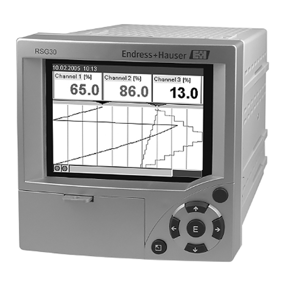
    Mise en service et exploitation Mise en service et exploitation Fonctions - Utilisation en cours de fonctionnement Fig. 7 : Affichage d'appareil / Unités de commande Elément de com- Fonction de commande mande (pos. N°) (Mode affichage ou mode configuration) En mode affichage : retour rapide au moment actuel En mode configuration : touche ESC pour interrompre la saisie ou pour un retour à...
  • Page 51: Régler La Langue De Service

    Mise en service et exploitation Elément de com- Fonction de commande mande (pos. N°) (Mode affichage ou mode configuration) Emplacement pour carte CF Touche d'éjection de la carte CF " Attention ! Ne pas activer lorsque la DEL (2b) est allumée ! Risque de perte de données ! DEL sur emplacement CF DEL est allumée lorsque l'appareil écrit ou lit des données sur la carte CF.
  • Page 52: Mise En Service

    Mise en service et exploitation Mise en service Après mise sous tension l'afficheur s'allume et l'appareil est prêt à fonctionner. • Lors de la mise en service d'un appareil déjà configuré ou préréglé, les mesures sont effectuées immédiatement, conformément aux réglages. Dans l'affichage apparaissent les valeurs du groupe actuellement réglées.
  • Page 53 Mise en service et exploitation Remarque ! Dans le logiciel PC fourni, l'interface USB est considérée comme un port COM (interface sérielle). Dans le gestionnaire Windows vous pouvez déterminer le port COM qui pilote l'appa- reil. Dans le gestionnaire, l'appareil est affiché sous "Raccordements (COM et LPT)" comme "ETU00xA (Com x)".
  • Page 54 Mise en service et exploitation - Dans le menu principal sélectionner "Fonctions CompactFlash (CF) / Copier la configu- ration sur la CF". - Dans le menu principal sélectionner "Fonctions CompactFlash (CF) / Retrait sécurisé de la CF". - Retirer la carte CompactFlash de l'appareil et la mettre en place dans le PC. Démarrer le logiciel PC et créer le nouvel appareil dans la base de données PC : - Sélectionner "Appareil ->...
  • Page 55 Mise en service et exploitation Fonction des touches dans la configuration Interruption de l'entrée ou retour à l'image précédente. Déplace le curseur vers la gauche ou la droite. Déplace la barre vers le haut ou le bas, modifie des paramètres /signes. : Touche Enter = sélection fonction marquée, démarrage de la modification de paramètre.
  • Page 56 www.endress.com/worldwide KA199R/09/a3/10.08 51009566 FM+SGML6.0 ProMoDo...

Table des Matières