Table des Matières
Publicité
Les langues disponibles
Les langues disponibles
Liens rapides
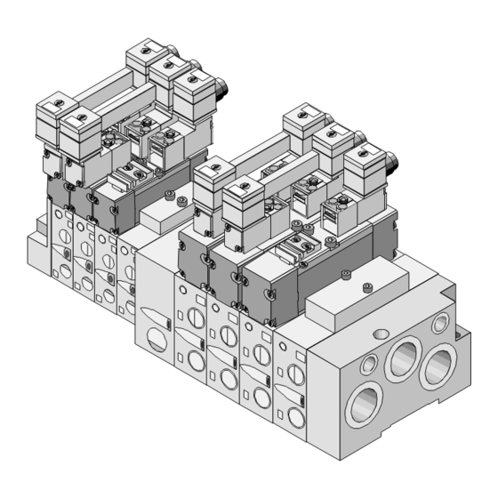
Brief description
Breve descripción
Kurzbeschreibung
Valve terminal
Terminal de válvulas
Ventilinsel
type VDMA-01/02
tipo VDMA-01/02
Typ VDMA-01/02
with
con
mit
single connection
conexión única
Einzelanschluß
Notice simplifiée
Manualetto
Beskrivning
Terminal de
Unità di valvole
Ventilterminal
distributeurs du type
tipo VDMA-01/02
typ VDMA-01/02
VDMA-01/02 avec
con
med
connessione singola
separatanslutning
connecteur individuel
9906NH
Publicité
Table des Matières

Manuels Connexes pour Festo VDMA-01


Sommaire des Matières pour Festo VDMA-01
- Page 1 Brief description Breve descripción Kurzbeschreibung Valve terminal Terminal de válvulas Ventilinsel type VDMA-01/02 tipo VDMA-01/02 Typ VDMA-01/02 with single connection conexión única Einzelanschluß Notice simplifiée Manualetto Beskrivning Terminal de Unità di valvole Ventilterminal distributeurs du type tipo VDMA-01/02 typ VDMA-01/02...
- Page 2 Svenska ........53 © (Festo AG & Co., D-73726 Esslingen, 1999) 9906NH...
- Page 3 VDMA-01/02 Benutzerhinweise Die Ventilinsel VDMA-... ist ausschließlich zur Steuerung von pneumatischen Aktuatoren bestimmt. Hierbei sind die angege- benen Grenzwerte für Drücke, Temperaturen, elektrische Daten, Drehmomente usw. einzuhalten. WARNUNG: • Schalten Sie die Spannung aus, bevor Sie Steckverbinder zusammenstecken oder trennen (Funktionsschädigung).
- Page 4 Unebene Oberflächen führen zur Leckage an der Ventilinsel. • Stellen Sie sicher, daß die Ventilinsel auf einer ebenen Fläche montiert wird (z.B. auf einer Stahlplatte). Zulässige Anziehdrehmomente bei der Ventilverkettung: VDMA-01: 0,4 Nm 0,5 Nm VDMA-02: 0,6 Nm 2 Nm...
- Page 5 VDMA-01/02 HINWEIS: • Vermeiden Sie dynamische Belastungen bei Verwendung der Hutschienenmontage. Anderfalls kann sich die Ventil- insel von der Hutschiene lösen. Bei geringen dynamischen Belastungen ist eine Hut- schienenbefestigung nur nach Einzelprüfung möglich. Montage an einer Hutschiene: 1. Ventilinsel an der Hutschiene einhängen.
- Page 6 VDMA-01/02 Pneumatisch HINWEIS: Verschlossene Abluftkanäle führen zu Fehlfunktionen der Ventile. • Stellen Sie sicher, daß der pneumatische Anschluß 12 der Ventilinsel nicht verschlossen wird. Er dient als Sammelleitung für die Vorsteuerentlüftung und kann gefasst weggeführt oder mit einem Schalldämpfer versehen werden.
- Page 7 VDMA-01/02 Pin-Belegung der Magnetventile WARNUNG: Die Verwendung von Ventilen mit unterschiedlicher Ansteuer- spannung kann zur Zerstörung der Ventilinsel führen. • Stellen Sie sicher, daß auf einer Ventilinsel nur Ventiltypen mit der gleichen Ansteuerspannung verwendet werden. Der Mischbetrieb von Ventilen mit unterschiedlicher An- steuerspannung ist nicht zulässig.
- Page 8 Bei Verwendung der Dose mit Kabel laut Zubehör **) Max. 24 V (- 15 % /+ 10 %) anschließen Hinweis zum Anschließen des Kabels Empfehlung: Verwenden Sie zum Anschluß der VDMA-Ventilinsel Kabel aus dem Zubehör von Festo. Dann ist die Schutzart IP65 sicherge- stellt. 9906NH...
- Page 9 VDMA-01/02 Zubehör Zubehör Zentralstecker mit Dose (max. 24 V) - Einzelanschluß MSSD-EB-M12-... / - Duoanschluß KMEB-1-... / SEA-M12-... Steckdose mit Kabel MSSD-EB /KMEB-1-... Bezeichnungsschilder IBS6x10 / IBS9x17 Bezeichnungsclip für IBS9x17 MN2H-BZT-... Deckplatte NDV-...-VDMA Verschlußscheibe NSC-...-VDMA Zwischenplatte NZV-01/02-VDMA Aufsatz für Handbetätigung...
- Page 10 VDMA-01/02 – Ventilbezeichnung Verwendung der Handhilfsbetätigung 9906NH...
-
Page 11: Technische Daten
Schaltnetzteile sind zulässig, wenn sie die sichere Tren- nung im Sinne der EN 60950/VDE 0805 gewährleisten. Anmerkung: Durch die Verwendung von PELV-Netzteilen wird bei Festo-Ven- tilinseln der Schutz gegen elektrischen Schlag (Schutz gegen direktes und indirektes Berühren) nach Maßgabe der EN 60204- 1/IEC 204 sichergestellt. - Page 12 - 5 °... + 50 °C Lagertemperatur - 20 °... + 40 °C Anziehdrehmomente - Befestigungsschrauben der Anschlußplatte 1,1 Nm - Ventilbefestigung 0,4 Nm (bei VDMA-01) - Anschlußkabel mit Dose 0,6 Nm (bei VDMA-02) 0,5 Nm Werkstoffe LABS-frei, GD-AL, NBR, St Elektromagnetische Nach EN 50082-2 Störfestigkeit...
- Page 13 VDMA-01/02 User instructions Valve terminal type VDMA-... has been designed exclusively for controlling pneumatic actuators. The specified maximum values for pressures, temperatures, electrical data, torques, etc. must be observed here. WARNING • Switch off the power supply before connecting or disconnecting cables.
- Page 14 Uneven surfaces can lead to leakage in the valve terminal. • Make sure, therefore, that the valve terminal is fitted on a flat surface (e.g. on a steel plate). Maximum permitted tightening torques for valve linking VDMA-01: 0.4 Nm 0.5 Nm VDMA-02: 0.6 Nm 2 Nm...
- Page 15 VDMA-01/02 PLEASE NOTE • Avoid dynamic stress when using the hat rail fitting. This will prevent the valve terminal from becoming detached from the hat rail. In the case of minor dynamic stress, a hat rail fitting is only possible after an individual check.
- Page 16 VDMA-01/02 Pneumatic components PLEASE NOTE Closed exhaust channels can lead to malfunctioning of the valves. • Make sure, therefore, that pneumatic port 12 on the valve terminal is not closed. This port serves as a common line for the auxiliary pilot exhaust and can be ducted or fitted with a silencer.
- Page 17 VDMA-01/02 Pin assignment of the solenoid valves WARNING The valve terminal may be damaged if valves with different control voltages are used. • Make sure, therefore, that only valve types with the same control voltage are used on a valve terminal.
- Page 18 If socket is used with cable as per "Accessories" **) Connect max. 24 V (- 15 %/+ 10 %) Notes on connecting the cable Recommendation: Use cables from the Festo range for con- necting the VDMA valve terminal. In this way you will comply with protection class IP65.
-
Page 19: Accessories
VDMA-01/02 Accessories Accessory Type Central plug with socket (max. 24 V) – individual connection MSSD-EB-M12-... / – double connection KMEB-1-... / SEA-M12-... Socket with cable MSSD-EB /KMEB-1-... Identification labels IBS6x10 / IBS9x17 Identification clip for IBS9x17 MN2H-BZT-... Cover plate NDV-...-VDMA Locking disc NSC-...-VDMA... - Page 20 VDMA-01/02 – Valve identification Using the manual override 9906NH...
-
Page 21: Technical Specifications
By using PELV power units, protection against electric shock (protection against direct and indirect contact) in accordance with EN 60204-1/IEC 204 is guaranteed on Festo valve termi- nals. Safety transformers with the adjacent designation must be used for supplying PELV networks. The valve terminals must be earthed in order to ensure their function (e.g. - Page 22 ...-110AC - AC 230 V (± 10 %) with valves type ...-230AC Protection class IP65 with connecting socket and cable from the Festo accessories Ambient temperature - 5 °... + 50 °C Storage temperature - 20 °... + 40 °C...
- Page 23 VDMA-01/02 Instrucciones para el usuario El terminal de válvulas VDMA-... ha sido diseñado exclusiva- mente para el control de actuadores neumáticos. En su utiliza- ción deben observarse los valores máximos especificados para presiones, temperaturas, datos eléctricos, pares, etc. ATENCIÓN: • Desconectar la fuente de alimentación antes de conectar o desconectar cables.
- Page 24 • Por ello, asegurarse de que el terminal de válvulas se monta sobre una superficie plana (p. ej. sobre una placa de acero). Pares de apriete máximos permitidos para el enlace de válvulas 0,5 Nm VDMA-01: 0,4 Nm VDMA-02: 0,6 Nm 2 Nm 9906NH...
- Page 25 VDMA-01/02 POR VAVOR, OBSERVAR: • Evitar la fatiga dinámica al usar el rail de montaje. Esto evitará que el terminal se decuelgue del raíl. En caso de una leve fatiga dinámica, hay que verificar específicamente el montaje sobre raíl. Fijación en un raíl de alas 1.
- Page 26 VDMA-01/02 Componentes neumáticos POR FAVOR, OBSERVAR: Si los canales de escape están bloqueados pueden impedir el funcionamiento de las válvulas. • Por ello, asegurarse de que la conexión neumática 12 del terminal de válvulas no está cerrada. Esta conexión es la línea común de los pilotajes auxiliares y puede ser con-...
- Page 27 VDMA-01/02 Asignación de pines de las electroválvulas ATENCIÓN: El terminal de válvulas puede dañarse si se utilizan válvulas con diferentes tensiones de control. • Por lo tanto, asegurarse de que se utilizan tipos de válvu- las con la misma tensión en el terminal de válvulas.
- Page 28 **) Tensión máx. 24 V (-15 % / +10 %) Notas sobre la conexión del cable Recomendación: Usar cables de la gama Festo para conectar el terminal de válvulas VDMA. De esta forma se cumplirá con la clase de protección IP65.
- Page 29 VDMA-01/02 Accesorios Accesorio Tipo Conector central con zócalo (máx. 24 V) – conexión individual MSSD-EB-M12-... / – conexión doble KMEB-1-... / SEA-M12-... Zócalo con cable MSSD-EB /KMEB-1-... Rótulo de identificación IBS6x10 / IBS9x17 Clip de identificación para IBS9x17 MN2H-BZT-... Placa ciega NDV-...-VDMA...
- Page 30 VDMA-01/02 – Identificación de la válvula Utilización del accionamiento manual 9906NH...
-
Page 31: Especificaciones Técnicas
VDMA-01/02 Especificaciones técnicas ATENCIÓN: Si se utiliza tipos de válvulas con tensión de control de 12 ó 24 V DC: • Utilizar solamente fuentes de alimentación que garanticen un aislamiento fiable de las tensiones de funcionamiento según IEC 742/EN 60742/VDE 0551 con una resistencia de aislamiento de por lo menos 4 kV (PELV, tensión extra... - Page 32 - AC 230 V (± 10 %) con válvulas tipo ...-230AC Clase de protección IP65 con conector y cable específi- co de "Accesorios" de Festo Temperatura ambiente - 5 °... + 50 °C Temperatura de - 20 °... + 40 °C...
- Page 33 VDMA-01/02 Instructions d’utilisation Le terminal de distributeurs VDMA-... est conçu exclusivement pour commander actionneurs pneumatiques. Simul- tanément, il convient de respecter les valeurs limites spécifiées pour les pressions, températures, données électriques, couples etc. DANGER : • Mettre hors tension avant de brancher ou de débrancher les connecteurs (sous risque d’endommagement du...
-
Page 34: Montage Du Terminal De Distributeurs
• S’assurer que le terminal de distributeurs est monté sur une surface plane (p. ex. sur une plaque d’acier). Couples de serrage admissibles pour le montage des distribu- teurs : 0,5 Nm VDMA-01 : 0,4 Nm VDMA-02 : 0,6 Nm 2 Nm 9906NH... - Page 35 VDMA-01/02 REMARQUE : • Eviter toute charge dynamique lors du montage sur rail. Sinon, le terminal distributeur risque de se détacher des rails. En cas de faibles charges dynamiques, le montage sur rail n‘est possible qu‘après une vérification préalable. Montage sur un rail : 1.
- Page 36 VDMA-01/02 Pneumatique REMARQUE : Les conduites d’échappement obstruées provoquent des dysfonctionnements dans les distributeurs. • S’assurer que le raccord pneumatique 12 du terminal de distributeurs n’est pas obstrué. Ce dernier sert de collecteur d’échappement de l’air de pilotage et et peut être branché ailleurs ou pourvu d’un silencieux.
-
Page 37: Affectation Des Broches Des Distributeurs
VDMA-01/02 Affectation des broches des distributeurs DANGER : L’utilisation de distributeurs ayant des tensions de comman- de différentes peut entraîner la destruction du terminal de di- stributeurs. • S’assurer qu’un même terminal de distributeurs utilise des bobines ayant une tension identique. - Page 38 **) Raccordement 24 V max. 24 V (- 15 % /+ 10 %) Remarque concernant le raccordement du câble Recommandation : Pour raccorder le terminal de distributeurs VDMA, utiliser des câbles faisant partie des accessoires Festo. Cela permet de ga- rantir par la suite l’indice de protection de IP65. 9906NH...
-
Page 39: Accessoires
VDMA-01/02 Accessoires Accessoires Connecteur commun avec prise (24 V max.) - Connexion unique MSSD-EB-M12-... / - Connexion duo KMEB-1-... / SEA-M12-... Prise avec câble MSSD-EB /KMEB-1-... Etiquettes de repérage IBS6x10 / IBS9x17 Clip de repérage pour IBS9x17 MN2H-BZT-... Plaque de couverture NDV-...-VDMA... - Page 40 VDMA-01/02 – Repérage du distributeur Utilisation de la clé pour l’actionnement manuel 9906NH...
-
Page 41: Caractéristiques Techniques
EN 60950/VDE 0805. Remarque : L’utilisation d’alimentation PELV garantit, sur les terminaux de distributeurs Festo, une protection contre l’électrocution (pro- tection des contacts directs et indirects) conformément à la nor- me EN 60204-1/CEI 204. Pour l’alimentation des blocs PELV, utiliser des transformateurs de sécurité comportant la marque d’identification ci-contre. - Page 42 - 20 °... + 40 °C Couples de serrage - Vis de fixation de la plaque de raccordement 1,1 Nm - Fixation du distributeur 0,4 Nm (pour VDMA-01) - Câble de raccordement et 0,6 Nm (pour VDMA-02) connecteur 0,5 Nm Matériaux Exempt de tout agent séparateur,...
-
Page 43: Indicazioni Per L'utilizzatore
VDMA-01/02 Indicazioni per l’utilizzatore L’unità di valvole VDMA-... è destinata esclusivamente all’azio- namento degli attuatori pneumatici nei limiti di pressione, tem- peratura, parametri elettrici, coppie ecc. previsti. AVVERTENZA: • Disattivare la tensione prima di inserire o disinserire i connettori (danni funzionali). - Page 44 • Accertarsi che l’unità di valvole venga montata su una superficie piana (ad es. su una lastra di acciaio). Coppie di serraggio consentite per il concatenamento delle val- vole: VDMA-01: 0,4 Nm 0,5 Nm VDMA-02: 0,6 Nm 2 Nm 9906NH...
- Page 45 VDMA-01/02 NOTA: • In caso di montaggio su guida "omega", evitare di applicare sollecitazioni dinamiche. L’unità di valvole può distaccarsi dalla guida "omega". Anche in presenza di sollecitazioni dinamiche limitate è op- portuno verificare ogni volta l’opportunità di serraggio me- diante guida "omega".
- Page 46 VDMA-01/02 Componenti pneumatici NOTA: L’intasamento dei canali di scarico altera il funzionamento delle valvole. • Accertarsi che la connessione pneumatica 12 dell’unità di valvole non sia intasata. Questa connessione ha la funzione di linea collettrice per lo scarico del prepilotaggio e può essere collegata a più...
- Page 47 VDMA-01/02 Occupazione dei pin delle elettrovalvole AVVERTENZA: L’impiego di elettrovalvole con tensioni di azionamento diver- se può danneggiare in modo irreparabile l’unità di valvole. • Accertarsi che su un’unità di valvole vengano installate solo valvole con tensioni di azionamento uguali.
- Page 48 **) Collegare max. 24 V (-15 % / +10 %) Indicazione per il collegamento del cavo Raccomandazione: Per il collegamento dell’unità di valvole VDMA utilizzare i cavi Festo indicati come accessori specifici. In tal modo è garantito il grado di protezione IP65. 9906NH...
- Page 49 VDMA-01/02 Accessori Denominazione Tipo Connettore centrale con connettore femmina (max. 24 V) - connessione singola MSSD-EB-M12-... / - connessione Duo KMEB-1-... / SEA-M12-... Connettore femmina cablato MSSD-EB /KMEB-1-... Targhette di identificazione IBS6x10 / IBS9x17 Clip di identificazione per IBS9x17 MN2H-BZT-...
- Page 50 VDMA-01/02 – Targhetta della valvola Utilizzo dell’azionatore manuale 9906NH...
-
Page 51: Dati Tecnici
"Chopper" solamente se in grado di garantire un seziona- mento sicuro ai sensi della normativa EN 60950/VDE 0805. Osservazione: Nelle unità di valvole Festo la protezione contro le scosse elet- triche (protezione dal contatto diretto e indiretto) viene ottenuta mediante impiego di alimentatori PELV in conformità alle dispo- sizioni della normativa EN 60204-1/IEC 204. - Page 52 - 20 °... + 40 °C Coppie di serraggio - Viti di sicurezza della piastra di raccordo 1,1 Nm - Fissaggio valvole 0,4 Nm (per VDMA-01) - Connettore cablato 0,6 Nm (per VDMA-02) 0,5 Nm Materiali Privo di sostanze contenenti grasso siliconico, GD-AL, NBR, acciaio Compatibilità...
- Page 53 VDMA-01/02 Anvisningar Ventilterminal av typ VDMA-... har konstruerats enbart för styr- ning av pneumatiska arbetselement. Angivna maxvärden för tryck, temperaturer, elektriska data, moment, etc. måste följas. VARNING: • Stäng av spänningen innan kontakter ansluts dras ut, (funktionsskador). OBS: Ta endast en komplett monterad och elektriskt ansluten ventilterminal i drift.
- Page 54 Mekaniska komponenter OBS: Ojämna ytor kan medföra att ventilterminalen läcker. • Se till att ventilterminalen monteras på jämn yta (t ex på en stålplatta). Maximalt tillåtet åtdragningsmoment vid ventilmonteringen 0,5 Nm VDMA-01: 0,4 Nm VDMA-02: 0,6 Nm 2 Nm 9906NH...
- Page 55 VDMA-01/02 OBS: • Se till att det inte finns dynamiska laster vid montering på spårskena. Annars finns det risk för att ventilenheten loss- nar från skenan. Om det finns små dynamiska laster får montering på spårs- kena ske endast efter undersökning för varje enskilt fall.
- Page 56 VDMA-01/02 Pneumatiska komponenter OBS: Pluggade avluftningskanaler kan medföra driftstörningar. • Se därför till att anslutning 12 på ventilterminalen inte är pluggad. Anslutningen fungerar som avluftning pilotluft och luften kan ledas bort eller så monteras en ljuddämpare. Användning av magnetventiler med separat styrluft Använd bara anslutning 14 på...
- Page 57 VDMA-01/02 Magnetventilens stifttilldelning VARNING: Ventilterminalen kan skadas om ventiler med olika styrspän- ningar används. • Se därför till att du bara använder ventiltyper med samma styrspänning på ventilterminalen. Blandad användning av ventiler med olika styrspänning är inte tillåten. – Monostabil ventil med M12-mittkontakt (2-polig)
- Page 58 VDMA-01/02 – Bistabil ventil med M12-mittkontakt (3-polig) typ MSSD-EB-M12-DUO: Stift Elanslutning Kabelfärg Beteckning – – brun ej använd signal (+) mag. 12 pilotmagnetspole 12 com (-) blå signal (+) mag. 14 svart pilotmagnetspole 14 Om kontakten används med kabel, se "Tillbehör"...
- Page 59 VDMA-01/02 Tillbehör Tillbehör Mittkontakt med hona (max 24 V) - Monostabil anslutning MSSD-EB-M12-... / - Bistabil anslutning KMEB-1-... / SEA-M12-... Kontakt med kabel MSSD-EB /KMEB-1-... Märkskylt IBS6x10 / IBS9x17 Märkskylthållare IBS9x17 MN2H-BZT-... Täckplatta NDV-...-VDMA Skiva för tryckzon NSC-...-VDMA Mellanplatta NZV-01/02-VDMA Handverktyg för manuell styrning...
- Page 60 VDMA-01/02 – Ventilbeteckning Manuell styrning 9906NH...
-
Page 61: Tekniska Data
VDMA-01/02 Tekniska data VARNING: Om du använder ventiler med 12 V = eller 24 V = styrspän- ning: • Använd bara nätenheter som garanterar isolationsklass enligt IEC 742/EN 60742/VDE 0551 med minst 4 kV isolationsklass (protected extra low voltage, PELV). - Page 62 - 5°... + 50° C Lagringstemperatur - 20°... + 40° C Åtdragningsmoment - fastsättningsskruvar till anslutningsplatta 1,1 Nm - ventilen 0,4 Nm (VDMA-01) - kontakt med 0,6 Nm (VDMA-02) anslutningskabel 0,5 Nm Material Innehåller inga lackpåverkande substanser (LABS-fri) GD-AL, NBR, St...