Publicité

Les langues disponibles

Les langues disponibles

Liens rapides

Cód. 50123467
Repetidor
Digital
RD-V2PLUS
Manual de instalación
version français (page 20)
english version (page 40)
TRD-V2PLUS ML rev.0213

Publicité

Table des Matières
loading

Sommaire des Matières pour golmar RD-V2PLUS

  • Page 1 Cód. 50123467 Repetidor Digital RD-V2PLUS Manual de instalación version français (page 20) english version (page 40) TRD-V2PLUS ML rev.0213...
  • Page 2: Table Des Matières

    INTRODUCCIÓN Ante todo le agradecemos y felicitamos por la adquisición de este producto fabricado por Golmar. Nuestro compromiso por conseguir la satisfacción de clientes como usted queda manifiesto por nuestra certificación ISO-9001 y por la fabricación de productos como el que acaba de adquirir.
  • Page 3: Precauciones De Seguridad

    O El monitor Tekna V2Plus Color debe ser V.02 ó posterior, para su compatibilidad con el repetidor. O IMPORTANTE: En la salida distribuida de un distribuidor no permite conectar otro distribuidor. O Utilizar el cable Golmar RAP-2150 en el sistema V2Plus.
  • Page 4: Modos De Funcionamiento

    Ver características, secciones y distancias en el manual del producto correspondiente. Nota: Si el repetidor/multiplexor está a una distancia menor a 50 metros de la placa, colocar el dip de ganancia de la placa SW1-6 a OFF . Bus: Cable Golmar RAP-2150...
  • Page 5 D: Repetidor en cascada (32 elementos por columna / 600 metros): 200m 150m 150m 100m ( ) 1 Viviendas EL500/V2Plus MC-V2Plus RD-V2Plus RD-V2Plus D1L ó D4L-V2Plus Hasta 32 monitores 25m. 0,75 mm 1,5 mm 1,5 mm 1,5 mm FA-V2Plus FA-V2Plus FA-V2Plus FA-V2Plus Bus: Cable Golmar RAP-2150 Continua.
  • Page 6 Ver características, secciones y distancias en el manual del producto correspondiente. Nota: Si el repetidor/multiplexor está a una distancia menor a 50 metros de la placa, colocar el dip de ganancia de la placa SW1-6 a OFF . Bus: Cable Golmar RAP-2150...
  • Page 7 1,5 mm FA-V2Plus FA-V2Plus Hasta 1 RD-V2Plus por cada salida distribuida del D1L ó D4L-V2Plus. Para esta aplicación contacte con nuestros servicios de asistencia técnica. ( ) 1 Importante: No superar el nº máx. de monitores/teléfonos conectados a una placa/multiplexor/repetidor, ni las distancias indicadas para placa/multiplexor/repetidor y último monitor y entre monitores de las distintas viviendas conectadas a la...
  • Page 8: Descripción Del Repetidor

    DESCRIPCIÓN escripción del repetidor. Leds de autodiagnóstico. Pulsador de rearme manual 'P1', por cruce en el Bus (columna/vertical). Etiqueta. Regleta de conexión Bus. Entrada alimentación (con alimentador FA-V2Plus) Lengüeta liberadora del carril DIN. INSTALACIÓN etalle de la instalación del repetidor. Instale el repetidor en un lugar seco y protegido sin riesgo de goteo o proyecciones de agua.
  • Page 9: Leds Autodiagnóstico

    LEDS AUTODIAGNÓSTICO escripción de los leds de autodiagnóstico. Los leds de autodiagnóstico están ubicados en la parte superior derecha del repetidor digital. Led verde Encendido fijo: Funcionamiento correcto. Parpadeo: Columna/vertical en comunicación. Apagado: Columna/vertical deshabilitada debido a un cruce en la columna * entre los hilos del bus. En caso de cruce, si este se elimina antes Led rojo de 2 minutos (aprox.), el repetidor se...
  • Page 10: Reposición

    Si uno de los tres primeros requisitos no se cumple, será preciso sustituir la vertical de la instalación. Si las derivaciones a vivienda se encuentran en buen estado, no será necesaria su sustitución. En caso de sustituir la vertical de instalación, utilice la manguera Golmar RAP-2150 y las siguientes secciones: Un acceso y una columna...
  • Page 11: Instalación De Reposición

    -La distancia máxima del multiplexor en cascada al último monitor B/N y entre monitores de las distintas viviendas (de la misma columna) conectados al multiplexor en cascada será de 100m. Golmar dispone de una manguera específica para este sistema, su referencia es RAP-2150. El uso de ( ) 1 esta manguera asegura un correcto funcionamiento del equipo y simplifica el cambio de la vertical al contener todos los hilos necesarios para la instalación.
  • Page 12 67m. 67m. IMPORTANTE: La distancia a incrementar con el repetidor, dependerá de la sección del cable instalado. (Consulte con nuestros servicios de asistencia técnica). Ver ej. de esquemas instalación pág. 15-16 y 18. Cable manguera Golmar RAP-2150, para instalaciones nuevas.
  • Page 13 Tekna V2Plus PA PB BUS IN BUS OUT Tekna V2Plus PA PB BUS IN BUS OUT FA-V2PLUS RD-V2Plus Configurar final de línea en el último monitor. - - + BUS IN BUS OUT P =Principal. Placa V2Plus FA-V2PLUS CV1 +12 - - + IMPORTANTE: Para la configuración y programación de cada equipo ver el manual de producto correspondiente.
  • Page 14 Tekna V2Plus Tekna V2Plus F.Linea PA PB PA PB BUS IN BUS OUT BUS IN BUS OUT FA-V2PLUS RD-V2Plus - - + BUS IN BUS OUT D4L-V2Plus Tekna V2Plus Tekna V2Plus F.Linea PA PB PA PB BUS IN BUS OUT...
  • Page 15 ESQUEMAS DE INSTALACIÓN ideoportero con distribuidor, 2 repetidores y abrepuertas de contínua. Ver ejemplo 'C' y notas importantes en 'modos de funcionamiento' (pág. 3). El esquema de instalación muestra el conexionado de un equipo de videoportero con una placa para acceder al edificio con distribuidores, 2 repetidores en cascada y abrepuertas de corriente continua.
  • Page 16 PA PB PA PB BUS IN BUS OUT BUS IN BUS OUT BUS IN BUS OUT FA-V2PLUS FA-V2PLUS RD-V2PLUS RD-V2PLUS - - + - - + BUS IN BUS OUT BUS IN BUS OUT MC-V2PLUS FA-V2PLUS - - + COL 1...
  • Page 17 PA PB PA PB BUS IN BUS OUT BUS IN BUS OUT FA-V2PLUS FA-V2PLUS RD-V2PLUS RD-V2PLUS - - + - - + BUS IN BUS OUT BUS IN BUS OUT Insertar el final de línea de 120 ohm, en el último distribuidor.
  • Page 18 PA PB BUS IN BUS OUT BUS IN BUS OUT R.1 20 FA-V2PLUS FA-V2PLUS D4L-V2Plus RD-V2PLUS RD-V2PLUS F.Linea - - + - - + BUS IN BUS OUT BUS IN BUS OUT A la Vertical 2 A la Vertical 3 Placa V2Plus P =Principal.
  • Page 19 BUS OUT Insertar resistencia final de línea de 120 ohm, en el último distribuidor. R.1 20 FA-V2PLUS FA-V2PLUS D4L-V2Plus RD-V2PLUS RD-V2PLUS F.Linea - - + - - + BUS IN BUS OUT BUS IN BUS OUT A la Vertical 2...
  • Page 21 Cód. 50123467 Répéteur Digital RD-V2PLUS manuel d'installation TRD-V2PLUS ML rev.0213...
  • Page 22: Conseils Pour La Mise En Marche

    Lorsque le système est mis en marche pour la première fois, ou après une intervention, le système sera inactif durant 45 secondes pour le temps de canal occupé initial. Utiliser le câble Golmar RAP-2150 dans le système V2Plus. Suivez à chaque instant les instructions de ce manual.
  • Page 23: Précautions De Sécurité

    O Le moniteur Tekna V2Plus Couleur doit être V.02 ou postérieur, pour sa compatibilité avec le répéteur. IMPORTANT: À la sortie distribué d'un distributeur, il ne permet pas de connecter un autre distributeur. O Utiliser le câble Golmar RAP-2150 dans le système V2Plus.
  • Page 24: Modes De Fonctionnement

    à la plaque/multiplexeur/répéteur. Pour les caractéristiques, sections et distances voir le manuel de produit correspondant. Remarque: Si le répéteur/multiplexeur est à une distance inférieure à 50 mètres de la plaque, placer le dip de la plaque SW1-6 à OFF . Bus: Câble Golmar RAP-2150...
  • Page 25 éléments par vertical / 600 mètres): 200m 150m 150m 100m ( ) 1 Habitations EL500/V2Plus MC-V2Plus RD-V2Plus RD-V2Plus D1L ou D4L-V2Plus jusqu'à 32 moniteurs 25m. 0,75 mm 1,5 mm 1,5 mm 1,5 mm FA-V2Plus FA-V2Plus FA-V2Plus FA-V2Plus Bus: Câble Golmar RAP-2150 Suite.
  • Page 26 à la plaque/multiplexeur/répéteur. Pour les caractéristiques, sections et distances voir le manuel de produit correspondant. Remarque: Si le répéteur/multiplexeur est à une distance inférieure à 50 mètres de la plaque, placer le dip de la plaque SW1-6 à OFF . Bus: Câble Golmar RAP-2150...
  • Page 27 25m. 0,75 mm 1,5 mm FA-V2Plus FA-V2Plus Jusqu'a 1 RD-V2Plus pour chaque sortie distribué du D1L ou D4L-V2Plus. our cette application, consulter notre service d'assistance technique. ( ) 1 Important: Ne pas dépasser le nombre max. de moniteurs/postes d' a ppel connectés à une plaque/multiplexeur/répéteur, ou les distances indiquées pour plaque/multiplexeur/répéteur et le dernier moniteur et entre les moniteurs de différents habitations...
  • Page 28: Description Du Répéteur

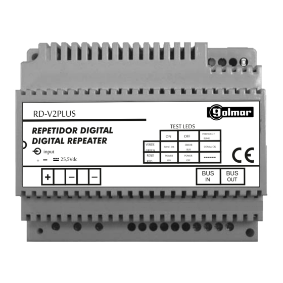
    DESCRIPTION escription du répéteur Leds d'autodiagnostique. Bouton de réarmement 'P1', par croisement dans le Bus (colonne/vertical). Etiquette. Réglette de connexion Bus. Entrée d'alimentation (avec alimentation FA-V2Plus) Languette libératrice du rail DIN. INSTALLATION étails de l'installation du répéteur Installer l'unité dans un endroit sec et protégé sans risque de dégouttement ou des projections d'eau. Pour éviter des dommages, le répéteur à...
  • Page 29: Leds Autodiagnostique

    LEDS AUTODIAGNOSTIQUE escription des leds d'autodiagnostique. Les leds d'autodiagnostique sont situées dans la partie supérieure droite du répéteur digital. Led verte Fixe: Bon fonctionnement. Clignotement: Colonne/vertical en communication. Éteinte: Colonne/vertical invalide en raison à un croisement dans la colonne * entre les fils du bus. En cas de croisement, si celui-ci est éliminé...
  • Page 30: Reposition

    REPOSITION Le portier vidéo Golmar V2PLUS est un système digital avec installation simplifiée (bus de 2 fils non polarisés), principalement pensé pour nouvelles installations et pour remplacer le portier audio déjà existants, aussi bien dans les collectivités que dans les pavillons.
  • Page 31: Installation Du Reposition

    100m. ( ) 1 Golmar possède un câble spécifique pour ce système, dont la référence est RAP-2150. L'utilisation de ce câble assure le bon fonctionnement de l'équipement et simplifie le changement de la colonne montante puisqu'il contient tous les fils nécessaires à l'installation.
  • Page 32 75m. 67m. 67m. IMPORTANT: La distance à augmenter par le répéteur dépendra de la section du câble installé. onsultez notre service d'assistance technique). Voir exemples de schémas d installation pages 35-36 et 38. Câble Golmar RAP-2150, pour les nouvelles installations.
  • Page 33 Tekna V2Plus PA PB BUS IN BUS OUT Tekna V2Plus PA PB BUS IN BUS OUT FA-V2PLUS RD-V2Plus Configurer fin de ligne sur le dernier moniteur. - - + BUS IN BUS OUT P =Principale. Réseau Plaque V2Plus FA-V2PLUS CV1 +12 - - + Réseau...
  • Page 34 D4L-V2Plus Tekna V2Plus Tekna V2Plus F.Linea PA PB PA PB BUS IN BUS OUT BUS IN BUS OUT FA-V2PLUS RD-V2Plus - - + BUS IN BUS OUT Réseau D4L-V2Plus Tekna V2Plus Tekna V2Plus F.Linea PA PB PA PB BUS IN...
  • Page 35 SCHÉMAS D'INSTALLATION ortier vidéo avec distributeur, 2 répéteurs et gâche électrique en courant continu. Voir l'exemple 'C' et notes importantes dans des 'modes de fonctionnement' (page 23). Le schéma d'installation montre la connexion d'un système de portier vidéo avec une plaque d'accès pour accéder au bâtiment et distributeurs D4L-V2Plus de 4 lignes, 2 répéteurs en cascade et gâche de courant continu.
  • Page 36 PA PB PA PB BUS IN BUS OUT BUS IN BUS OUT BUS IN BUS OUT FA-V2PLUS FA-V2PLUS RD-V2PLUS RD-V2PLUS - - + - - + BUS IN BUS OUT BUS IN BUS OUT Réseau Réseau MC-V2PLUS FA-V2PLUS - - +...
  • Page 37 F.Linea PA PB PA PB BUS IN BUS OUT BUS IN BUS OUT FA-V2PLUS FA-V2PLUS RD-V2PLUS RD-V2PLUS - - + - - + BUS IN BUS OUT BUS IN BUS OUT Réseau Réseau Insérer la résistance de fin de ligne de 120 ohm, dans le dernier distributeur.
  • Page 38 PA PB PA PB BUS IN BUS OUT BUS IN BUS OUT R.1 20 FA-V2PLUS FA-V2PLUS D4L-V2Plus RD-V2PLUS RD-V2PLUS F.Linea - - + - - + BUS IN BUS OUT BUS IN BUS OUT Réseau Réseau À la Vertical 2 À...
  • Page 39 BUS IN BUS OUT Insérer la résistance de fin de ligne de 120 ohm, dans le dernier distributeur. R.1 20 FA-V2PLUS FA-V2PLUS D4L-V2Plus RD-V2PLUS RD-V2PLUS F.Linea - - + - - + BUS IN BUS OUT BUS IN BUS OUT Réseau Réseau...
  • Page 41 Cód. 50123467 Digital Repeater RD-V2PLUS Instructions manual TRD-V2PLUS ML rev.0213...
  • Page 42 When starting the equipment for the first time, or after a modification, the system will remain inactive for around 45 seconds due to the initial busy channel time Use Golmar RAP-2150 cable in the...
  • Page 43: Safety Precautions

    O The Tekna V2Plus Color monitor must be the version V.02 or later, for its compatibility with the repeater. IMPORTANT: In the output of a distributor cannot be connected another distributor O Use Golmar RAP-2150 cable in the V2Plus system.
  • Page 44: Operation Modes

    For characteristics, sections and distances see the corresponding product manual. Note: If the repeater/multiplexer is at a distance less than 50 meters from the door panel, place in the door panel the dip gain SW1-6 to OFF . Bus: Golmar RAP-2150 cable.
  • Page 45 D: Repeater in daisy chain (32 elements for riser / 600 meters): 200m 150m 150m 100m ( ) 1 Apartments EL500/V2Plus MC-V2Plus RD-V2Plus RD-V2Plus D1L or D4L-V2Plus Up to 32 monitors 25m. 0,75 mm 1,5 mm 1,5 mm 1,5 mm FA-V2Plus FA-V2Plus FA-V2Plus FA-V2Plus Bus: Golmar RAP-2150 cable. Continue...
  • Page 46 For characteristics, sections and distances see the corresponding product manual. Note: If the repeater/multiplexer is at a distance less than 50 meters from the door panel, place in the door panel the dip gain SW1-6 to OFF . Bus: Golmar RAP-2150 cable.
  • Page 47 1,5 mm FA-V2Plus FA-V2Plus Up to 1 RD-V2Plus for each distributed output of D1L or D4L-V2Plus distributor. For this operation mode contact our technical support department. ( ) 1 Important: Do not exceed the max. monitors/telephones connected to a door panel/multiplexer/repeater, or the distances indicated for door panel/multiplexer/repeater and last monitor and monitors between different apartments connected to door panel/multiplexer/repeater.
  • Page 48: Description Of The Repeater

    DESCRIPTION escription of the repeater. Autodiagnostic LEDs. Reset button 'P1', for short-circuit Bus (riser where repeater is connected). Label. Bus connection block. Power supply input (with FA-V2Plus power supply). DIN rail latch release. INSTALLATION etail of the repeater installation. Install the repeater in a dry and protected place without risk of drip or water projections.
  • Page 49: Autodiagnostic Leds

    AUTODIAGNOSTIC LEDS escription of autodiagnostic LEDs. The autodiagnostics LEDs are placed on the top right of the digital repeater. Green Led Fixed: Correct operation. Blinking: Riser communicating. Off: Riser not functioning due to a short-circuit in the riser * between the bus wires. If the short circuit is eliminated before Red Led 2 minutes (approx.), the repeater will...
  • Page 50: Replacement

    REPLACEMENT The Golmar V2PLUS video door entry system is a digital system with simplified installation (2 wire bus without polarity), designed to new installations and to replace existing audio door entry systems in both apartment blocks and villas. In installation for replacement it is necessary a detailed study of the existing installation before installing the system.
  • Page 51: Installation Of Replacement

    (in the same riser) connected to multiplexer in daisy chain will be:100m. ( ) 1 Golmar has a special cable for this system, its reference number is RAP-2150. The use of this cable ensures the correct functioning of the system and simplifies the riser replacement given that it contains all the necessary wires for the installation.
  • Page 52 75m. 67m. 67m. IMPORTANT: The distance to increase with repeater, it will depend on the installed cable section. ontact our technical support department ). See examples of installation diagrams, page 55-56 and 58. Use Golmar RAP-2150 cable, for new installations.
  • Page 53: Installation Diagrams

    Tekna V2Plus PA PB BUS IN BUS OUT Tekna V2Plus PA PB BUS IN BUS OUT FA-V2PLUS RD-V2Plus Configuring the end of line in the last monitor. - - + BUS IN BUS OUT M =Master. Main V2Plus door panel FA-V2PLUS...
  • Page 54 D4L-V2Plus Tekna V2Plus Tekna V2Plus F.Linea PA PB PA PB BUS IN BUS OUT BUS IN BUS OUT FA-V2PLUS RD-V2Plus - - + BUS IN BUS OUT Main D4L-V2Plus Tekna V2Plus Tekna V2Plus F.Linea PA PB PA PB BUS IN...
  • Page 55 INSTALLATION DIAGRAMS ideo door entry system with distributor, 2 repeaters and d.c lock release. See example 'C' and important notes in 'operation modes' (pág. 43). The installation diagram shows the connection of a video door entry system with one door panel to access the building with distributors, 2 repeaters in daisy chain and d.c lock release.
  • Page 56 PA PB PA PB BUS IN BUS OUT BUS IN BUS OUT BUS IN BUS OUT FA-V2PLUS FA-V2PLUS RD-V2PLUS RD-V2PLUS - - + - - + BUS IN BUS OUT BUS IN BUS OUT Main Main MC-V2PLUS FA-V2PLUS - - +...
  • Page 57 F.Linea PA PB PA PB BUS IN BUS OUT BUS IN BUS OUT FA-V2PLUS FA-V2PLUS RD-V2PLUS RD-V2PLUS - - + - - + BUS IN BUS OUT BUS IN BUS OUT Main Main Insert a 120 ohm end of line resistor in the last distributor.
  • Page 58 PA PB PA PB BUS IN BUS OUT BUS IN BUS OUT R.1 20 FA-V2PLUS FA-V2PLUS D4L-V2Plus RD-V2PLUS RD-V2PLUS F.Linea - - + - - + BUS IN BUS OUT BUS IN BUS OUT Main Main To riser 2 To riser 3 V2Plus door panel M =Master.
  • Page 59 BUS IN BUS OUT Insert a 120 ohm end of line resistor in the last distributor. R.1 20 FA-V2PLUS FA-V2PLUS D4L-V2Plus RD-V2PLUS RD-V2PLUS F.Linea - - + - - + BUS IN BUS OUT BUS IN BUS OUT Main Main...
  • Page 60 Golmar se reserva el derecho a cualquier modificación sin previo aviso. Golmar se réserve le droit de toute modification sans préavis. Golmar reserves the right to make any modifications without prior notice.

Table des Matières