NewAge Products Pro Serie Mode D'emploi
Masquer les pouces
Voir aussi pour Pro Serie:
- Instructions d'installation (7 pages) ,
- Guide d'installation rapide (2 pages)
Table des Matières
Publicité
Les langues disponibles
Les langues disponibles
Liens rapides
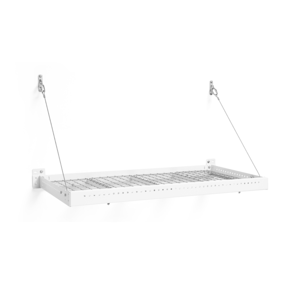
4x8ft Wall Mounted Shelf
Warning: Excessive weight hazard!
Use two or more people to move, assemble or install cabinets and locker to avoid back injury.
Do not leave children unattended near cabinets. High risk of tipping if cabinets are installed
incorrectly: securely attach cabinets to the wall to avoid serious injury.
For assistance, call 1.877.306.8930; for UK 0800.031.4069; e-mail at info@newageproducts.com
STOP
Pro Series
Warning: Excessive weight
hazard!
Use two or more people to move, assemble, or install
Wall Mounted Shelf to avoid back or other injury. Do
not leave children unattended near Wall Mounted
Shelf. High risk of items falling if Wall Mounted
Shelf is installed incorrectly: must be securely
installed to avoid serious injury. For assistance, call
1.877.306.8930; e-mail at info@newageproducts.
com.
ATTENTION
Is your Wall Mounted Shelf damaged?
Need help or spare parts?
For fastest service, contact NewAge Products at
1-877-306-8930; or support@newageproducts.com.
Do not return to the retailer.
:
Publicité
Chapitres
Table des Matières

Manuels Connexes pour NewAge Products Pro Serie


Sommaire des Matières pour NewAge Products Pro Serie
- Page 1 For assistance, call 1.877.306.8930; e-mail at info@newageproducts. com. ATTENTION STOP Is your Wall Mounted Shelf damaged? Need help or spare parts? For fastest service, contact NewAge Products at 1-877-306-8930; or support@newageproducts.com. Do not return to the retailer.
-
Page 2: Table Des Matières
INDEX Product Overview: Safety Warning - 3 Tools Needed - 5 Included Quantities - 6 Spare Parts - 7 Weight Capacity - 8 Installation Overview - 9 Installation Overview: Installation Options - 10 Wall Configuration: Installation Location - 11 Ceiling Configuration: Installation Location - 12 Installing Wall Brackets &... -
Page 3: Safety Warning
As such, do not stand, jump or hang from your Wall Mounted Shelf. 4. Wall Mounted Shelf units must be installed into structurally sound overhead/wall joists or supports. NewAge Products Inc. make no claim to the capacity or strength of the structure to which the units are mounted. - Page 4 When this product is installed, operated and maintained according to the instructions attached to or furnished with the product, NewAge Products Inc. will replace the defective product or parts if the part fails as a result of defective materials or workmanship for the Lifetime of the product.
-
Page 5: Tools Needed
Unpacking • Begin by placing the package on a covered flat surface. • Remove all cardboard, packaging material and clear plastic bags. • Dispose / recycle all packaging materials. • Verify all the contents in the box and gather the required tools. See “Tools Needed” , and “Included Quantities”... -
Page 6: Included Quantities
Included Quantities 4x8ft Pro Series Wall Mounted Shelf Part Number DESCRIPTION QTY. Part Number DESCRIPTION QTY. QTY. WSH-01A-01-XX 4x8ft Pro Series Wall Mounted Shelf H00004A-01 1/4-20x0.75in Hex Bolt WSH-01.001A-01-XX Front 'c' channel - RHS 1/4-20 Lock Nut H00005A-01 WSH-01.002A-01-XX Front 'c' channel - LHS H00006A-01 5/16-18x1.25in Hex Bolt WSH-01.003A-01-XX... -
Page 7: Spare Parts
Spare Parts SKU 40480 Part # : WSH-01.014A-01 Cable Assembly 4ft Cable Assembly 4mm cable Turnbuckle C-Shaped Clamp Capel Quick Link Connector SKU 40482 Part # : WSH-01.015A-01 Pad Eye Plates SKU 40484 Part # : WSH-01.006A-01-BS Black - Back Hanging Brackets SKU 40485 Part # : WSH-01.006A-01-WH White- Back Hanging Brackets... -
Page 8: Weight Capacity
Weight Capacity lbs. lbs. lbs. Two Linked Wall Single Wall Mounted Shelf Mounted Shelves Installed Vertically lbs. lbs. Two Linked Wall Mounted Shelves Installed Horizontally lbs. lbs. lbs. Three Linked Wall Mounted Shelves Installed Horizontally lbs. lbs. lbs. lbs. Four Linked Wall Mounted Shelves Installed Vertically & Horizontally Safety Warning: All Wall Mounted Shelf units have a rated load capacity of 600 pounds, evenly distributed, using 3”... - Page 9 Wall Mounted Shelf Installation Overview Plan your Wall Mounted Shelf Determine your preferred configuration installation location, determine before beginning assembly. (Page 10) orientation and verify spacing of studs. (Page 11-12) • Wall brackets must be fully secured to studs using 1 lag bolt each or to concrete wall using 1 concrete anchor.
-
Page 10: Installation Options
Installation options for Wall Mounted Shelf Option A Important information: Please read entire manual before beginning Single Wall Mounted Shelf attached to wall. installation. (Start on page 11, Option A ) • Layouts shown are examples only. • Do not exceed total weight capacity of Wall Mounted Shelf. - Page 11 Ceiling Mounted: Plan the Installation Location 18-32” Wall Mounted: 26” Option A: Installing Wall Mounted Shelf To the Wall Once it is determined that your Wall Mounted Shelf will be installed to the wall, verify there is sufficient clearance. Mark the desired position of the bottom of the Wall Mounted Shelf with a horizontal level line across the wall.
- Page 12 Plan Installation Location Ceiling Mounted: 18-32” Option B: Installing Wall Mounted Shelf To the Ceiling Wall Mounted: 26” Once it is determined that your Wall Mounted Shelf will be installed to the ceiling, verify there is sufficient clearance. Mark the desired position of the bottom of the Wall Mounted Shelf with a horizontal level line across the wall.
-
Page 13: Installing Wall Brackets & Back Beam
Installing Wall Brackets & Back Beam Start installation with the middle Drill a pilot hole using a 3/16” drill bit. hanging bracket. Note: Pilot hole must bore into 3 inches Align the bottom of the Wall Mounting of solid wood for lag screw to be fully Bracket (#6) with the bottom level line and secured. - Page 14 Mark next location for pilot hole using the wall mounting bracket (#6) and rear perimeter beam (#5). Follow steps i through iii below. Insert the Wall Mounting Bracket and Carriage Bolt onto the Rear Perimeter Beam. Mount the Rear Perimeter Beam onto the previously installed Wall Mounting Bracket.
- Page 15 Installing Pad Eye Plate Option A: Wall Configuration Wall Mounting: Measure and mark 35” vertically from the bottom of the Wall Mounted bracket (#6) to the top of the pad eye plate (#22) . Align the pad eye plate on the center of the stud and the top of the eye plate below the level line and mark the wall for pilot holes.
-
Page 16: Perimeter Beam & Cable Assembly
Perimeter Beam & Cable Assembly Option A: Wall Configuration Attach cable eyelet to side beam (#3/#4) using 5/16” bolt (#19) , nut (#20) and fender washer (#23) Wall Mounted Cable Assembly: Insert a 5/16” Hex Bolt into the 57th hole of the side perimeter beam. - Page 17 Ceiling Mounted Depth: (5/16”) (1/4” dia x 3”) (5/16” dia x 1”) (1/4” dia x 3/4”) (1/4” dia x 3/4”) 20” Concrete Anchor Lock Nut Washer (5/16” x 3”) (5/16”) (1/4”) (1/4”) 4ft Cable Assembly with Turnbuckle Installing Pad Eye Plate Option B: Ceiling Configuration Ceiling Mounted: 18-32”...
- Page 18 Perimeter Beam & Cable Assembly Option B: Ceiling Configuration Attach cable eyelet to side beam (#3/#4) using 5/16” bolt (#19), nut (#20) and fender washer (#23) Ceiling Mounted Cable Assembly: Attach the Cable Eyelet (#21) to the respective hole according to the distance measured from the ceiling to the bottom of the Wall Mounted Shelf.
- Page 19 Attach the Quick Link Connector (#21) to the Pad Eye Plate (#22). Note: Adjust Turnbuckle (A) of Cable Assembly so threads are even on both sides for easier adjustment when mounting to pad eye plate (B). Attach Side Beam( #3/#4) by guiding the mounting holes into the carriage bolt (#8) and shoulder rivet on the wall bracket.
- Page 20 Bolt together the front perimeter beams (#1 / #2) with the front perimeter bracket (#7) with eight 1/4” carriage bolts (#8) , washers (#9) and acorn nuts (#10). Begin with the vertical Bolts (i) followed by the horizontal Bolts (ii) Note: Ensure the acorn nuts are on the outside of the front...
-
Page 21: Cross Support Assembly
4ft Cross Support Assembly (i) Assemble the 4ft Cross Supports (#13) with one 1/4” hex bolt (#17) and 1/4” lock nut (#18). (ii) Attach the assembled 4ft cross supports to the perimeter frame with four hex bolts (#17), eight washers (#9), and four lock nuts (#18) Grid Supports &... - Page 22 Moving inward, place remaining bottom “U” Shaped Grid Supports and Grid Sections onto the Wall Shelf. Once the “U” Shaped Grid Supports and Grid Sections have been installed, level the Wall Shelf front to back by adjusting the turnbuckles accordingly. Wall Mounted Ceiling Mounted Warning:...
-
Page 23: Installation Tips
Installation Tips Installing with Irregular Joist Spacing Pad eye plates can be positioned up to 6 inches side to side or 12 inches front to back to align with a ceiling joist. If you are not installing the pad eye plates in the intended location, the height of the shelf needs to be adjusted according to the values in the table on page 24. - Page 24 Values found in table below are the distance between the bottom of your wall mounted shelf and the ceiling. (C). Note: Pad eye plate can be positioned up to 6inches side to side or 12 inches front to back. Distance from Original Celing Loca�on (Inches) (A) 17 7/8 17 3/4 17 1/2...
- Page 25 If the spacing of your ceiling joists do not match the desired size and direction of your Wall Mounted Shelf installation you will need to install a joist in the correct position. Please consult your local professional contractor for assistance installing a joist hanger. Using suitable joist hangers, install two additional wooden ceiling joists in the desired location.
-
Page 26: Fastening To Engineered Joists
If the spacing of your wall studs do not match the desired size and direction of your Wall Mounted Shelf installation, you will need to install a horizontal support brace in the correct position (minimum 2” x 8”). Install an additional horizontal support brace in the required locations for your wall mounting depending on the Wall Mounted Shelf and orientation as determined on page... -
Page 27: Connecting Wall Mounted Shelf Horizontally
Connecting Wall Mounted Shelves Horizontally Note: Before installing the Wall Install first wall shelf according to Mounting Brackets, ensure wall option A (Wall Mounted) or B (Ceiling mounted bracket will be shared Mounted), until reaching Step 12 on between two shelves that both carriage page 16 or page 18. -
Page 28: Connecting Wall Mounted Shelf Vertically
Connecting Wall Mounted Shelf Vertically Once you have followed steps 1 to 8 for the Fully Install upper wall shelf according lower wall shelf, install the pad eye plates on to option A (Wall Mounted) or B your upper wall shelf according to diagram (Ceiling Mounted). -
Page 29: Connecting Corner Wall Mounted Shelf
Connecting Corner Wall Mounted Shelf Note: If installing two 4ftx8ft and one 4ftx4ft Wall Mounted Shelves in an L configuration, follow instructions starting on 1B of this page: 1/4” Begin installing the 4ftx4ft Wall Mounted Shelf by following the instructions below. If you are only installing Wall Mounted Shelves in one direction, follow the instructions on page 27 - “Connecting Wall Mounted Shelves Horizontally”,... - Page 30 Attach the Rear Perimeter Beam followed by the Side Perimeter Beam. Bolt together the 4ftx4ft Wall Mounted Shelf Front Perimeter Beam with the Side Perimeter Beam of the next Wall Mounted Shelf using one hex bolt and lock nut. Attach the Cable Assembly through both Perimeter Beams. Proceed and complete the assembly of the second Wall Mounted Shelf beginning on Step 3 (pg.13) of the Installation Manual.
- Page 31 1.877.306.8930; E-mail à info@ newageproducts.com. ATTENTION ARRÊT Votre étagère murale est-elle endommagée? Besoin d’aide ou de pièces de rechange? Pour un service rapide, contactez NewAge Products au 1-877-306-8930; ou support@newageproducts. com. Ne retournez pas chez le détaillant.
-
Page 32: Aperçu De Produit
INDEX Aperçu de produit: Avertissement de sécurité - 3 Outils nécessaires - 5 Quantités incluses - 6 Pièces de rechange -7 Capacité de poids - 8 Aperçu de l’installation - 9 Aperçu de l'installation: Options d’installation - 10 Configuration du mur: Emplacement d’installation - 11 Configuration de plafond: Emplacement d'installation - 12 Installation des supports muraux et de la poutre arrière - 13, 14 Configuration murale: Installation de la plaque à... -
Page 33: Alerte De Sécurité
4. Les étagères doivent être installées dans des solives ou des supports de sol / mur / plafond. NewAge Products Inc. ne prétend pas à la capacité ni à la résistance de la structure sur laquelle les unités sont montées. -
Page 34: Garantie À Vie Limitée Du Fabricant
Products Inc. remplacera les pièces ou le produit défectueux advenant que ceux-ci découlent d’un défaut de matériel ou de fabrication pendant la durée de vie du produit. NEWAGE PRODUCTS INC. N’ASSUMERA PAS LES COÛTS SUIVANTS : Les appels de service pour corriger l’installation de tout produit NewAge ou pour vous montrer comment les utiliser ou les installer. -
Page 35: Déballage
Déballage • Commencer par placer le paquet sur une surface plane couverte. • Enlever les cartons, le matériel d’emballage en mousse et les sacs en plastique transparents. • Jeter/recycler tous les matériaux d’emballage. • Vérifier le contenu de la boîte et rassembler les outils requis. •... -
Page 36: Quantités Incluses
Quantités incluses Série Pro - Etagère 4pi x 8pi Numéro de pièce Numéro de pièce DESCRIPTION QTE. DESCRIPTION QTY. QTE. WSH-01A-01-XX Etagère murale série Pro. 4 pi x 8 pi H00004A-01 1/4-20x0.75in Boulon Hexagonale WSH-01.001A-01-XX Poutre en forme”C” - Coté droit 1/4-20 Ecrou de blocage H00005A-01 WSH-01.002A-01-XX... -
Page 37: Pièces De Rechange
Pièces de rechange SKU 40480 Part # : WSH-01.014A-01 L’assemblage de poulie L”assemblage Cable 4mm Tendeur Crampon on forme de C Connecteur serti Maillon Rapide SKU 40482 Part # : WSH-01.015A-01 Plaque à oeillet SKU 40484 Part # : WSH-01.006A-01-BS Noir - Supports de suspension arrière SKU 40485 Part # : WSH-01.006A-01-WH... -
Page 38: Capacité De Poids
Capacité de poids lbs. lbs. lbs. Deux étagères murales Une seule étagère reliées installées verticalement lbs. lbs. Deux étagères murales reliées installées horizontalement lbs. lbs. lbs. Trois étagères murales reliées installées horizontalement lbs. lbs. lbs. lbs. Quatre étagères murales reliées installées verticalement ou horizontalement Avertissement de sécurité: Toutes les étagères murales ont une capacité... -
Page 39: Vue D'ensemble De L'installation D'une Étagère Murale
Vue d’ensemble de l’installation d’une étagère murale Planifiez l’emplacement de votre Déterminez votre configuration préférée tablette murale, déterminez avant de commencer l’assemblage. l’orientation et vérifiez l’espacement des (Voir:Page 10) montants. (Voir:Page 11-12) • Les fixations murales doivent être entièrement fixées aux montants à l’aide d’un tire-fond chacune ou au mur en béton à... -
Page 40: Options D'installation
Options d’installation pour l' étagère murale Option A Informations importantes: Veuillez lire le manuel en entier avant de Étagère murale simple fixée au mur. commencer l’installation. (Commencez à la page 11, option A) • Les mises en page présentées ne sont que des exemples. -
Page 41: Planifier L'emplacement D'installation
Ceiling Mounted: Planifier l’emplacement d’installation 18-32” Wall Mounted: 26” Option A: Installation d’une étagère murale au mur Une fois que vous avez déterminé que votre étagère murale sera installée contre le mur, vérifiez que le dégagement est suffisant. Marquez la position souhaitée du bas de la tablette murale avec une ligne horizontale de niveau sur le mur. - Page 42 20” 4ft Cable Assembly with Turnbuckle Planifier l’emplacement d’installation Ceiling Mounted: 18-32” Option B: Installation d’une étagère murale au plafond Wall Mounted: 26” Une fois que vous avez déterminé que votre étagère murale sera installée au plafond, vérifiez que le dégagement est suffisant. Marquez la position souhaitée du bas de la tablette murale avec une ligne horizontale de niveau sur le mur.
-
Page 43: Installation Des Supports Muraux Et De La Poutre Arrière
Installation de supports muraux et de poutre arrière Alignez le bas du support de montage Percez un avant-trou avec un foret de mural (n ° 6) avec la ligne de niveau 3/16 ”. inférieure et le centre du montant Remarque: le trou pilote doit percer mural avec le centre de la fente dans 3 pouces de bois massif pour que la horizontale du support de fixation... - Page 44 Marquez l’emplacement suivant pour le trou pilote à l’aide du support de fixation mural (n ° 6) et de la poutre périphérique arrière (n ° 5). Suivez les étapes (i) à (iii) ci-dessous. Insérez le support de fixation murale et le boulon de carrosserie sur le faisceau de périmètre arrière.
-
Page 45: L' Installation Du Plaque À Ouillet
L’ installation du plaque à ouillet Option A: Configuration du mur Montage Mural: Mesurez et marquez 35 pouces verticalement du bas du support mural (n ° 6) au sommet de la plaque à oeillets (n ° 22). Alignez la plaque à oeillets sur le centre du goujon et le haut de la plaque à... -
Page 46: Poutre Périmétrique Et Câble
Poutre périmétrique et câble Option A: Configuration du mur Fixez l’œillet du câble à la poutre latérale (n ° 3 / n ° 4) à l’aide d’un boulon de 5/16 po (n ° 19), d’un écrou (n ° 20) et d’une rondelle (n ° 23). Assemblage du câble monté... -
Page 47: L'installation Du Plaque À L'œillet
Ceiling Mounted Depth: (5/16”) (1/4” dia x 3”) (5/16” dia x 1”) (1/4” dia x 3/4”) (1/4” dia x 3/4”) 20” Concrete Anchor Lock Nut Washer (5/16” x 3”) (5/16”) (1/4”) (1/4”) 4ft Cable Assembly with Turnbuckle L’installation du plaque à l’œillet Option B: Configuration de plafond Ceiling Mounted: 18-32”... -
Page 48: Assemblage De Câble
Poutre périmétrique et assemblage de câble Option B: Configuration de plafond Fixez l’œillet du câble à la poutre latérale (n ° 3 / n ° 4) à l’aide d’un boulon de 5/16 po (n ° 19), d’un écrou (n ° 20) et d’une rondelle (n ° 23). Câble monté... - Page 49 Fixez le connecteur Quick Link (n ° 21) à la plaque à œillets de protection (n ° 22). Remarque: Réglez le tendeur (A) de l’ensemble de câbles de sorte que les filets soient même des deux côtés pour faciliter le réglage lors du montage sur la plaque à...
- Page 50 Boulonnez les poutres périmétriques avant (n ° 1 / n ° 2) avec le support périmétrique avant (n ° 7) à l’aide de huit boulons de carrosserie 1/4 ”(n ° 8), de rondelles (n ° 9) et l’écrou de dômes (n ° 10). Commencez par les boulons verticaux (i) suivis des boulons horizontaux (ii) Remarque: Assurez-vous que les écrous...
-
Page 51: Assemblage De Support Croisé De 4 Pieds
Assemblage de support croisé de 4 pieds (i) Assemblez les supports transversaux de 4 pieds (n ° 13) avec un boulon hexagonal de 1/4 ”(n ° 17) et un écrou de blocage de 1/4” (n ° 18). (ii) Fixez les supports transversaux de 4 pieds assemblés au cadre périmétrique avec quatre boulons à... - Page 52 En vous déplaçant vers l’intérieur, placez les autres supports de grille en forme de «U» et les sections de grille en bas sur l’étagère murale. Une fois que les supports de grille en forme de «U» et les sections de grille ont été...
-
Page 53: Conseils D'installation
Conseils d’installation Installation avec espacement irrégulier des solives Les œillets peuvent être positionnés jusqu’à 6 pouces d’un côté à l’autre ou 12 pouces d’avant en arrière pour s’aligner sur une solive de plafond. Si vous n’installez pas les œillets de protection à l’emplacement prévu, la hauteur de l’étagère doit être ajustée en fonction des valeurs indiquées dans le tableau de la page 24. - Page 54 Les valeurs figurant dans le tableau ci-dessous correspondent à la distance entre le bas de votre étagère murale et le plafond. (C) Remarque: La plaque pour œillets peut être positionnée jusqu’à 6 pouces latéralement ou 12 pouces entre l’avant et l’arrière. Distance du lieu de plafond d'origine (pouces) (A) 17 7/8 17 3/4...
- Page 55 Si l’espacement de vos solives de plafond ne correspond pas à la taille et à la direction souhaitées pour l’installation de votre étagère murale, vous devrez installer une solive dans la position correcte. Veuillez consulter votre entrepreneur professionnel local pour obtenir de l’aide pour l’installation d’un support de solive.
-
Page 56: Fixation Aux Solives D'ingénierie
Si l’espacement de vos poteaux muraux ne correspond pas à la taille et à la direction souhaitées pour l’installation de votre étagère murale, vous devrez installer une entretoise de support horizontale dans la position correcte (minimum 2 po x 8 po). Installez une entretoise de support horizontale supplémentaire aux emplacements requis pour votre montage mural en fonction... -
Page 57: Raccordement Horizontal Des Étagères Murales
Raccordement horizontal des étagères murales Remarque: avant d’installer les supports Installez la première étagère murale de fixation murale, assurez-vous que le conformément à l’option A (montage support mural est partagé entre deux mural) ou B (montage au plafond) étagères et que les deux boulons de jusqu’à... -
Page 58: Raccordement Vertical Des Étagères
Raccordement vertical des étagères murales Installez entièrement la tablette murale Une fois que vous avez suivi les étapes 1 à 8 pour supérieure selon l’option A (montage l’étagère murale inférieure, installez les œillets de mural) ou B (montage au plafond). protection sur votre étagère murale supérieure conformément au schéma ci-dessous. -
Page 59: Étagère De Raccordement Au Mur
Étagère de raccordement au mur Remarque: Si vous installez deux étagères murales 4pix8pi et une 4pix4pi dans une configuration en L, suivez les instructions commençant en 1B sur cette page: 1/4” Commencez à installer l’étagère de 4pi x 4pi en suivant les instructions ci-dessous. - Page 60 Fixez le faisceau de périmètre arrière suivi du faisceau de périmètre latéral. Boulonnez ensemble la poutre de périmètre avant de l’étagère murale 4pi x 4pi avec la poutre de périmètre latérale de la prochaine étagère murale à l’aide d’un boulon à tête hexagonale et d’un écrou de blocage. Fixez l’ensemble de câbles à...