
Manuels Connexes pour Samlex Solar SCC-30AB

Sommaire des Matières pour Samlex Solar SCC-30AB
- Page 1 30 Amp Owner's Please read this manual before Manual Solar Charge operating your charge controller. Controller SCC-30AB...
-
Page 2: Table Des Matières
INDEX 1. Safety Instructions ....................3 2. General Description of PV / Solar System ............5 3. General information - Batteries ..............15 4. Introduction and Features ................28 5. Construction, Layout and Controls ..............33 6. Installation and Operation ................38 7. -
Page 3: Installation Environment
SAFETY INSTRUCTIONS Please read these instructions before installing or operating the Charge Controller to prevent per- sonal injury or damage to the Charge Controller. General Installation and wiring compliance • Installation and wiring must comply with the local and National Electrical Codes and must be done by a certified electrician. - Page 4 SAFETY INSTRUCTIONS • Use caution to reduce the risk of dropping a metal tool on the battery. It could spark or short circuit the battery or other electrical parts and could cause an explosion. • Remove metal items like rings, bracelets and watches when working with batteries. The batteries can produce a short circuit current high enough to weld a ring or the like to metal and cause a severe burn.
-
Page 5: General Description Of Pv / Solar System
GENERAL DESCRIPTION OF PV / SOLAR SYSTEM What is Photovoltaic (PV)? The word ‘photo-voltaic’ is derived from two different words; the word ‘photos’, from the Greek, meaning light and the word ‘voltaic’ developed from the name of the Italian scientist, Volta, who studied electricity. This explains what a PV system does: it converts light energy from the sun into electrical energy. - Page 6 Charge Controller DC-AC Power Inverter To AC Loads GENERAL DESCRIPTION OF PV / SOLAR SYSTEM Grid-tied PV / Solar System PV/Solar Panel (Module) or Array Battery Fig. 2.2 shows a Block Diagram of a typical Grid-tied PV / Solar System. In this system, the Solar Panels (Modules) / Arrays directly feed to an inverter and the inverter is connected to an Electricity Transmission and Distribution System (referred to as the Electricity Grid) such that the system can draw on the Grid’s reserve capacity in times...
- Page 7 GENERAL DESCRIPTION OF PV / SOLAR SYSTEM PV / Solar Cell 12cm Fig. 2.3. PV / Solar Cell The basic element of a PV System is the photovoltaic (PV) cell, also called a Solar Cell. An example of a PV / Solar Cell made of Mono-crystalline Silicon is shown in Fig. 2.3. This single PV / Solar Cell is like a square, but with its four corners missing (it is made this way!).
- Page 8 GENERAL DESCRIPTION OF PV / SOLAR SYSTEM When light enters the PV / Solar Cell, some of the “Photons” (packets of electro- magnetic wave energy) from the light energy are absorbed by the semiconductor atoms. The energy of the absorbed light is transferred to the negatively charged electrons in the atoms of the solar cell.
- Page 9 GENERAL DESCRIPTION OF PV / SOLAR SYSTEM The materials used in PV / Solar Cells have different spectral responses to incident light, and exhibit a varying sensitivity with respect to the absorption of photons at given wavelengths. Each semiconductor material will have an incident radiation threshold frequency, below which no electrons will be subjected to the photovoltaic effect. ...
- Page 10 GENERAL DESCRIPTION OF PV / SOLAR SYSTEM PV Cell Types PV cells are most commonly made of Silicon, and come in two varieties, crystalline and thin-film type, as detailed in Table 2.1 Cell types include Mono-crystalline Silicon, Poly-crystalline Silicon, Amorphous Silicon (a-Si), Gallium Arsenide (GaAs), Copper Indium Diselenide (CuInSe2, „CIS“), Cadmium Telluride, or a combination of two materials in a tandem cell.
- Page 11 GENERAL DESCRIPTION OF PV / SOLAR SYSTEM Cell Module Array Fig. 2.5. PV cell, Module and Array The cells are very thin and fragile so they are sandwiched between a transparent front sheet, usually glass, and a backing sheet, usually glass or a type of tough plastic. This protects them from breakage and from the weather.
- Page 12 GENERAL DESCRIPTION OF PV / SOLAR SYSTEM Bypass Diodes As mentioned, PV / Solar cells are wired in series and in parallel to form a PV / Solar Panel (Module). The number of series cells indicates the voltage of the Panel (Module), whereas the number of parallel cells indicates the current.
- Page 13 General Description of pV/solar system A Current (I) versus Voltage (V) Curve of a PV / Solar Module (“I-V” Curve) shows the possible combinations of its current and voltage outputs. A typical I-V curve for a 12 V Module is shown in Fig. 2.8. The power in a DC electrical circuit is the product of the voltage and the current.
- Page 14 General Description of pV/solar system The rated power of the PV / Solar Module in Watts (Pmax) is derived from the above values of voltage Vmp and current Imp at this Maximum Power Point (MPP): • Rated power in Watts, Pmax = Vmp X Imp Example of I-V Curve and Ratings of a 12 V PV / Solar Panel Fig.
-
Page 15: General Information: Batteries
GENERAL INFORMATION: BATTERIEs Battery Types There are several different types of battery chemistries like Lead-Acid, Nickel-Iron (Ni-Fe), Nickel-Cadmium (Ni-Cad) etc. The batteries consist of individual cells that can be connected in series to obtain the required battery voltage. Batteries are either sealed (also called Valve Regulated Lead Acid - VRLA) or non-sealed / vented / flooded / wet cell. - Page 16 GENERAL INFORMATION: BATTERIEs During charging, reverse electrochemical reactions take place. Under the influence of the charging voltage fed to the battery by the external battery charger / charge controller, electrons are fed back to the battery and the Lead Sulphate at the Positive and Negative Plates is converted back to Lead Dioxide at the Positive Plate and Lead at the Negative Plate and the concentration of Sulphuric Acid is restored (will revert to 33.5% v/v when the battery is fully charged).
- Page 17 GENERAL INFORMATION: BATTERIEs Sealed Lead Acid (SLA) or Valve regulated Lead Acid (VRLA) Batteries Sealed Lead Acid (SLA) batteries or Valve Regulated Lead Acid (VRLA) batteries can either be Gel Cell or AGM (Absorbed Glass Mat). In a Gel Cell battery, the electrolyte is in the form of a gel.
- Page 18 GENERAL INFORMATION: BATTERIEs The holes in the grid of the plates are filled with a paste of active material made out of a mixture of Red Lead and 33% dilute Sulphuric Acid (different manufacturers use modified mixtures). The paste is pressed into the holes in the grid. This paste remains porous and allows the Sulphuric Acid in the electrolyte to react with the lead inside the plate increasing the surface area many fold.
- Page 19 GENERAL INFORMATION: BATTERIEs This type of battery is not recommended for the storage of energy for inverter applications. However, they are recommended as starting battery for the back-up generator. Deep Cycle Lead Acid Batteries Deep cycle batteries are designed with thick-plate electrodes to serve as primary power sources, to have a constant discharge rate, to have the capability to be deeply discharged up to 80 % capacity and to repeatedly accept recharging.
-
Page 20: Usable Capacity
GENERAL INFORMATION: BATTERIEs Reduction in Usable Capacity at Higher Discharge Rates As stated above, the rated capacity of the battery in AH is normally applicable at a discharge rate of 20 Hours. As the discharge rate is increased, the usable capacity reduces due to “Peukert Effect”. - Page 21 GENERAL INFORMATION: BATTERIEs PERCENTAGE OF STANDING VOLTAGE OF CELL VOLTAGE (12 V BATTERy FULL CHARGE 12 V NOMINAL BATTERy HAS 6 CELLS IN SERIES) 12.63 V 2.105 V 100% 12.6 V 2.10 V 12.5 V 2.08 V 12.3 V 2.05 V 12.2 V 2.03 V 12.1 V...
- Page 22 GENERAL INFORMATION: BATTERIEs Effect of Temperature on Battery Voltage The temperature of the electrolyte affects the rate of chemical reactions in the batteries as well as the rate of diffusion and the resistivity of the electrolyte. Therefore, the charging characteristics of the battery will vary with temperature. This is nearly linear and the Voltage Coefficient of Temperature Change is normally taken as -3 mV to -5 mV / ºC / Cell.
- Page 23 GENERAL INFORMATION: BATTERIEs Loss of Battery Capacity at Low Temperatures Batteries lose capacity in low temperatures. At 32 ºF (0 ºC), a battery will deliver about 70 to 80 % of its rated capacity at 80 ºF (26.7 ºC). If the electrolyte temperature of the battery bank is lower than 80 ºF (26.7 ºC), additional batteries will be needed to provide the same usable capacity.
-
Page 24: Parallel Connection
GENERAL INFORMATION: BATTERIEs Positive terminal of Battery 4 becomes the Positive terminal of the 24 V bank. The Negative terminal of Battery 4 is connected to the Positive terminal of Battery 3. The Negative terminal of Battery 3 is connected to the Positive terminal of Battery 2. The Negative terminal of Battery 2 is connected to the Positive terminal of Battery 1. - Page 25 GENERAL INFORMATION: BATTERIEs Figure 3.4 above shows a series – parallel connection consisting of four 6V, 200 AH batteries to form a 12 V, 400 AH battery bank. Two 6 V, 200 AH batteries, Batteries 1 and 2 are connected in series to form a 12 V, 200 AH battery (String 1). Similarly, two 6 V, 200 AH batteries, Batteries 3 and 4 are connected in series to form a 12 V, 200 AH battery (String 2).
- Page 26 GENERAL INFORMATION: BATTERIEs Sizing the Inverter Battery Bank One of the most frequently asked question is, “how long will the batteries last?” This question cannot be answered without knowing the size of the battery system and the load on the inverter. Usually this question is turned around to ask “How long do you want your load to run?”...
- Page 27 GENERAL INFORMATION: BATTERIEs As explained, tt will be seen from the above that the final rated capacity of the batteries is almost 2 times the energy required by the load in AH. Thus, as a Rule of Thumb, the AH capacity of the batteries should be twice the energy required by the load in AH.
-
Page 28: Introduction And Features
IntroductIon & features The SCC-30AB is a Series Type of PWM (Pulse Width Modulation) Charge Controller. It is based on an advanced design using a microcontroller for digital accuracy and fully automatic operation. It can be used for 12V or 24V systems for solar charging . The PWM battery charging has been optimized for longer battery life. - Page 29 (called Shunt) connected MOSFET Switch. During the initial constant current, Bulk Charge Stage (see Fig. 4.1) the Series connected MOSFET Switch (in a Series Type of controller like SCC-30AB) is kept on continuously till the PWM Absorption Voltage is reached. During this time the...
- Page 30 Although the SCC-30AB’s battery charging is fully automatic, the following information is important for getting the best performance from your SCC-30AB Charge Controller and battery. Four Stages of Solar Charging Fig.
- Page 31 IntroductIon & features 1. Bulk Charging: In this stage, the battery will accept all the current provided by the solar array. The value of this current will be equal to the Short Circuit Current Isc of the solar array. 2. PWM Absorption: When the battery reaches the Absorption Voltage, the PWM begins to hold the voltage constant.
- Page 32 IntroductIon & features Normal charging of the battery can convert the sulfate back to the soft active material if the battery is fully recharged. However, a solar battery is seldom completely recharged, so the soft lead sulfate crystals harden over a period of time. Only a long controlled overcharge, or equalization, at a higher voltage can reverse the hardening sulfate crystals.
-
Page 33: Construction, Layout And Controls
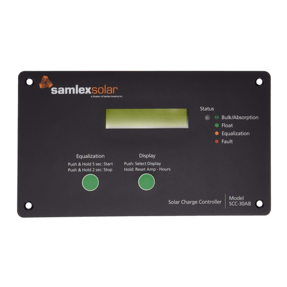
ConstruCtion, layout & Controls General SCC-30AB is designed for flush mounting on a wall / panel. The controls and indications are built on the Front Panel face plate that has 4 countersunk holes for flush mounting (Fig. 5.1). All the electronics, DIP switches for settings, terminal strip... - Page 34 ConstruCtion, layout & Controls Controls & Indications The description and the functions of the controls and indications are given below: Front Panel Charge Status LED Indications LED STATE INDICATION Charging is in the state of Bulk or Absorption Blinking Green depending upon the number of blinks as follows: For 12 V Battery For 24 V Battery...
-
Page 35: Lcd Display
ConstruCtion, layout & Controls LCD Display The LCD Display is a 2 Line, 16 character display with backlighting. The Push Switch marked “PUSH Select Display” and “HOLD – Reset Amp Hours” is used to manipulate the LCD functions. Every time the Push Switch is pressed momentarily, the screen display scrolls. - Page 36 ConstruCtion, layout & Controls The details of information provided in the LCD screens are given below: Screen 1 • Shows the solar array current / charging current in Amperes (Amp), battery voltage in V (BatV) and the power delivered by the solar array / fed to the batteries in Watts (Watts). The value of Watts = the charging current in Amperes (Amp) x Battery Voltage in V (BatV).
-
Page 37: Fault Messages
ConstruCtion, layout & Controls Fault Messages The LCD displays might have the following fault messages when SCC-30AB stops operating. DISPLAy DESCRIPTION CAUSE OF FAULT Alarm: OC Over Current The current exceeds 15% of the rated current Over Current Alarm: OT Heat Sink over Heat sink temperature exceeds 90°C. -
Page 38: Installation And Operation
• The connector terminals will accept a maximum wire size of AWG #10 (up to 5.2 mm • Tighten each terminal clamping screw to 20 inch-pounds of torque. • The SCC-30AB is designed to regulate power from a PV array. Other chargers can be connected directly to the battery, however, with no effect on the SCC-30AB. - Page 39 2. Make sure the PV currents will not exceed the ratings of the SCC-30AB. 3. The connections to the SCC-30AB terminals are shown in the drawing at Fig. 5.2. A barrier type of Terminal Strip has been provided for connecting the PV array and the battery.
-
Page 40: Dip Switch Settings
130% of rated current by regulating the current to safe levels. If the current from the solar array exceeds 150%, the controller will interrupt charging. Battery Types: The SCC-30AB’s standard battery charging programs are suitable for a wide range of Lead-Acid battery types. These standard programs are select by DIP... - Page 41 InstallatIon & operatIon Standard Battery Charging Programs The SCC-30AB provides 8 standard battery charging algorithms (programs) that are selected with DIP Switches 2, 3, 4. These standard algorithms are suitable for Lead-Acid batteries ranging from sealed (Gel, AGM, maintenance free) to flooded to L-16 cells and Ni-Cd etc.
- Page 42 Manual Equalization The SCC-30AB is shipped with the DIP Switch 5 set for manual equalization only. This is to avoid an unexpected or unwanted automatic equalization. In the Manual Mode, the push button marked “Equalization” is used to both start and stop a manual equalization.
- Page 43 InstallatIon & operatIon Temperature Compensated Battery Charging An optional Battery Temperature Sensor (BTS), Model No. DC-BTS-A-C is available for temperature compensated battery charging. The BTS consists of a temperature sensing probe that is installed on the + battery post. The temperature of the battery post reflects the approximate temperature of the electrolyte.
- Page 44 InstallatIon & operatIon The temperature sensed by the BTS at the battery is displayed on the LCD screen under the screen display “Heatsink BTS” (see Fig. 5.3). As the LCD display is not capable of displaying negative values, battery temperature below 0 ºC will not be displayed.
-
Page 45: Troubleshooting
TroubleshooTing The SCC-30AB is very rugged and designed for the most extreme operating conditions. Most PV system problems will be caused by connections, voltage drops, and loads. Troubleshooting the SCC-30AB controller is simple. Some basic troubleshooting procedures are listed below. - Page 46 If it is unable to maintain its voltage, the battery may be failing. • Measure the PV voltage and the battery voltage at the SCC-30AB terminals. If the voltage at the terminals is the same (within a few tenths of volts) the PV array is charging the battery.
-
Page 47: Specifications
SpecificationS CHARACTERISTICS SPECIFICATIONS SySTEM 12 VDC or 24 VDC Nominal system voltage (Selected by DIP Switch) Current rating 30 A Set point accuracy + / - 50 mV Minimum voltage to start the micro-controller, 9 VDC for 12 V Battery System activate protections and guide operation 18 VDC for 24 V Battery System Total self consumption current... - Page 48 SpecificationS CHARACTERISTICS SPECIFICATIONS ENVIRONMENTAL Ambient temperature 0 ºC to + 45 ºC Storage temperature - 55 ºC to + 85 ºC Humidity 95% Non Condensing MECHANICAL 7.48 x 4.25 x 1.38 inches Dimensions (L x W x D) 190 x 108 x 35 mm Weight (With gift box) 1.2 lbs / 0.55 kg Net weight...
-
Page 49: Warranty
5 yEAR Limited Warranty SCC-30AB manufactured by Samlex America, Inc. (the “Warrantor“) is warranted to be free from defects in workmanship and materials under normal use and service. The warranty period is 5 years for the United States and Canada, and is in effect from the date of purchase by the user (the “Pur- chaser“). - Page 50 Information Toll Free Numbers Ph: 800 561 5885 Fax: 888 814 5210 Local Numbers Ph: 604 525 3836 Fax: 604 525 5221 Website www.samlexamerica.com USA Shipping Warehouse Kent WA Canadian Shipping Warehouse Delta BC Email purchase orders to orders@samlexamerica.com 11010-SCC-30AB-0912...
- Page 51 Régulateur Guide Veuillez consulter ce manuel AVANT de solaire d’utilisation d’installer votre régulateur de 30 Amp charge solaire SCC-30AB...
- Page 52 INDEX 1. Mesures de sécurité .................... 1 2. Introduction et caractéristiques ................ 3 3. Installation, Présentation & Commandes ............8 4. Installation et fonctionnement ............... 13 5. Résolution des problèmes ................22 6. Spécifications ....................24 7. GARANTIE ......................26 Pour en savoir plus sur les systèmes et batteries solaires PV Rendez-vous sur www.samlexamerica.com et consultez les publications de Samlex :...
-
Page 53: Environnement D'installation
MESURES DE SÉCURITÉ Veuillez lire attentivement ces instructions avant d’installer ou d’utiliser votre régulateur de charge afin d’empêcher toutes blessures personnelles et dommages au régulateur de charge. Général Installation et conformité du branchement électrique • L’installation et le branchement du circuit électrique doivent être conformés aux Codes électriques locaux et nationaux (NEC) et doivent être effectués par un électricien professionnel. -
Page 54: À Propos Du Régulateur De Charge
• Le conducteur négatif du système doit être correctement mis à la terre. La mise à terre doit être conformé aux codes électriques locaux. Le SCC-30AB est un régulateur de charge de type de MLI (Modulation de Largeur d’Impulsion). C’est un appareil à la conception avancée qui utilise un microcontrôleur offrant une précision numérique et une utilisation entièrement automatique. -
Page 55: Présentation Et Caractéristiques
PRÉSENTATION ET CARACTÉRISTIQUES Caractéristiques • Microcontrôleur avancé, haute performance conçue permettant une précision numérique et une utilisation entièrement automatique et facile • Double tension – peut être utilisé avec des systèmes solaires 12V / 24V • Capacité de charge de 30A – permet une utilisation jusqu‘à 360 W de 12V ou 720 Watts de 24V de panneaux solaires •... -
Page 56: Régulateur De Charge De Type Shunt Ou En Série
PRÉSENTATION ET CARACTÉRISTIQUES Au cours de la phase de charge de masse en courant constant initial (voir Fig. 4.1), l’interrupteur MOSFET en série connecte (contrôleur en série de type SCC-30AC) est conserve jusqu’a ce que la tension d’absorption MLI soit atteinte. Au cours de cette charge, le panneau solaire délivre un courant constant qui est égal ou presque a un courant de court-circuit Isc correspondant à... -
Page 57: Algorithme Du Chargement De La Batterie
Sélection de la meilleure méthode de chargement de votre batterie ainsi qu’un programme d’entretien assurera une longue vie et un bon fonctionnement à votre batterie. Bien que le chargement de la batterie de type SCC-30AB est entièrement automatique, les informations suivantes sont importantes afin d’obtenir les meilleurs résultats de votre régulateur de charge SCC-30AB et de votre batterie. -
Page 58: Égalisation
PRÉSENTATION ET CARACTÉRISTIQUES Égalisation ATTENTION ! • L’égalisation est effectuée uniquement pour les batteries non étanches / à plomb ouvert / au plomb acide / noyées. • Ne pas égaliser de batteries AGM / étanche à électrolytes et de type VRLA. •... - Page 59 PRÉSENTATION ET CARACTÉRISTIQUES Dissout l’électrolyte Dans les batteries inondées, en particulier celles à électrolytes, l’acide le plus lourd tombe au fond de la cellule au cours du temps. Cette stratification de l’électrolyte provoque une réduction des capacités de la batterie ainsi qu’une corrosion de la partie la plus basse des plaques. La gazéification de l’électrolyte dû...
-
Page 60: Installation, Présentation & Commandes
& commandes Général Le modèle SCC-30AB est conçu pour être monté sur un mur ou un panneau. Les commandes et indications sont intégrées sur le panneau frontal de la plaque qui est composée de 4 trous à vis permettant de l’encastrer (Fig. 5.1). Toute l’électronique, les interrupteurs DIP pour les réglages, le raccordement pour les connections du groupe PV, la batterie et les bornes... -
Page 61: Panneau Frontal
installation, prÉsentation & commandes Commandes & Indications La description et les fonctions des commandes et indications sont indiquées ci-dessous : Panneau frontal Indications LED du statut de charge ÉTAT DE LA LED INDICATION Vert clignotant La charge est en phase de masse ou d’absorption selon le nombre de clignotants suivants: Pour une batterie de 12V Pour une batterie de 24V... -
Page 62: Affichage Lcd
installation, prÉsentation & commandes Boutons poussoir BOUTONS ACTION Affichage Appuyez pour modifier l’affichage comme en Fig.5.3 Régler les Appuyez et maintenez pour régler les Amp-heures Amp-Heures Egalisation Lorsque l’interrupteur DIP 5 est sur OFF, appuyez sur Démarrer/Arrêter Redémarrer/Arrêter l’égalisation pendant 5 secondes pour démarrer manuellement l’égalisation. - Page 63 installation, prÉsentation & commandes Écran d’af chage LED Amp Watts BatV Écran 1 12.0 APPUYEZ : Sélectionnez l’af chage Amp-Heures Écran 2 0 Ah APPUYEZ : Sélectionnez l’af chage Total Amp-Heures Écran 3 0 Ah PUSH: Display Select APPUYEZ : Sélectionnez l’af chage Mode: Chargeur Écran 4 État : Masse...
- Page 64 installation, prÉsentation & commandes Les informations détaillées fournies sur les écrans LCD sont indiquées ci-dessous : Écran 1 • Affiche le courant / la charge de courant du générateur solaire en Ampères (Amp), la tension de la batterie en V (BatV) et la puissance délivrée au générateur solaire / transférée aux batteries en Watts (Watts).
-
Page 65: Messages D'erreurs
InstallatIon et fonctIonnement Messages d’erreurs L’affichage LCD peut délivrer des messages d’erreur lorsque le SCC-30AV cesse de fonctionner. AFFICHAGE DESCRIPTION SOURCE DE L’ERREUR Alarme : SI Surintensité Le courant excède de 15% le courant évalué Surintensité Alarme : ST Sur-température du dis- La température du dissipateur excède les 90°C sipateu Alarme : CPF00... -
Page 66: Étapes D'installation
être directement connectés a la batterie, cependant, cela n’affecte en rien le SCC-30AB. Étapes Étapes 1 : Comme expliqué auparavant dans le Chapitre 4, le SCC-30AB est conçu pour être monté sur un panneau mural. Il dispose d’une face plate et d’une partie saillante a l’arrière compose d’un circuit imprimé, d’un connecteur pour le capteur thermique de la batterie... - Page 67 Étapes 2 : Assurez-vous que les courants PV ne dépasseront pas les classifications du SCC-30AB. Étapes 3 : Les connections aux terminaux du SCC-30AB sont présentés sur le schéma en Fig. 5.2. Un terminal de raccordement est fourni pour connecter le groupe PV et la batterie.
-
Page 68: Réglages De L'interrupteur Dip
130% du courant évalué, en régulant le courant à des niveaux sûrs. Si le courant du générateur solaire dépasse 150%, le régulateur interrompra la charge. Type de batteries : Les programmes de charge de la batterie standard SCC-30AB sont adaptés à une large gamme de batterie de type plomb-acide. Ces programmes standards sont sélectionnés à... - Page 69 InstallatIon et fonctIonnement standards sont adaptés pour des batteries de type plomb-acide allant des batteries étanches (gel, AGM, sans entretien) aux batteries inondées, en passant par les batteries a cellules L-16 et Ni-Cd, etc. Le tableau 6.1. ci-dessous présente les paramètres principaux des algorithmes de charge standards.
-
Page 70: Procédure D'égalisation
Égalisation manuelle Le SCC-30AB est livré avec un ensemble de 5 interrupteurs DIP uniquement pour une égalisation manuelle. Cela permet d’éviter une égalisation automatique non- souhaitée ou non-attendue. En mode manuel, le bouton « égalisation », est utilisé... -
Page 71: Charge De Batterie Par Compensation De Température
InstallatIon et fonctIonnement Si l’égalisation ne peut pas être effectuée en un jour, elle se poursuivra le jour suivant ou pendant quelques jours jusqu’à ce qu’elle soit achevée. Une fois l’égalisation soit terminée, la charge retournera au stade d’absorption MLI. Charge de batterie par compensation de température Une sonde de Température-Batterie (STB) optionnelle, modèle No. - Page 72 InstallatIon et fonctIonnement Maintien La charge de maintien est moins affectée par les variations de température, mais peut également sous charger ou gazéifier de manière trop importante, en fonction de la variation de température. La sonde de température-batterie (STB) corrige les points de réglage de la charge mentionnes au-dessus par les valeurs suivantes (température de référence est de 25°C / 77°F) : •...
-
Page 73: Temperature De L'électrolyte De La Batterie
InstallatIon et fonctIonnement La compensation est affichée dans le Tableau 6.2 : COMPENSATION DE LA TENSION TEMPERATURE DE L’ÉLECTROLYTE DE LA BATTERIE BATTERIE DE 12 V BATTERIE DE 24 V 50 ºC / 122 ºF – 0.75 V –1.50 V 45 ºC / 113 ºF –... -
Page 74: Résolution Des Problèmes
RÉsolution des pRoblemes Le SCC-30AB est très solide et conçue pour des utilisations dans des conditions extrêmes. La plupart des problemes liés aux systèmes PV sont causés par les branchements, les chutes de tension et les charges. Résoudre les problèmes liés au régulateur SCC-30 AB est simple. Certaines procédures de résolution sont présentées ci-dessous. - Page 75 Si la batterie ne peut maintenir sa tension, la batterie peut être défectueuse. • Mesurez la tension du PV et celle de la batterie SCC-30AB à ses bornes. Si la tension aux bornes est la même (a quelques dizaines de volts près), le groupe PV charge la batterie.
-
Page 76: Spécifications
SpecificationS CHARACTÉRISTIQUES SPECIFICATIONS SYSTEME 12 VDC ou 24 VDC Tension nominale du système (sélection avec interrupteur DIP) Valeur du courant Valeur de réglage + / - 50 mV 9 VDC pour système de batterie de 12V Tension minimum pour démarrer le micro régulateur, activer les protections et permettre le fonctionnement 18 VDC pour système de batterie de 24V Autoconsommation totale de courant... -
Page 77: Environnement
SpecificationS CHARACTÉRISTIQUES SPECIFICATIONS ENVIRONNEMENT Température ambiante 0 ºC A + 45 ºC Température de stockage - 55 ºC A + 85 ºC Humidité 95% sans condensation MECANIQUE 7.48 x 4.25 x 1.38 pouces Dimensions (L x L x H) 190 x 108 x 35 mm Poids (avec boite) 1.2 lbs / 0.55 kg Poids net... - Page 78 GUARANTIE SCC-30AB fabriqué par Samlex America, Inc. (le « Garant ») est garanti d’être non défectueux dans la conception et dans les matériaux, moyennant une utilisation et un service normaux. La période de garantie est de 5 ans pour les Etats-Unis et le Canada, et prend effet le jour de l’achat par l’utilisateur («...
- Page 79 GUARANTIE y compris les garanties implicites liées a la garantie de qualité marchande, a l’usage des objectifs habituels pour lesquels de telles marchandises sont utilisées, ou l’usage pour un objectif particulier, ou toutes autres obligations de la part du Garant ou de ses employés et représentants.
- Page 80 Tel : 1 800 561 5885 Fax : 1 888 814 5210 Numéros locaux Tel : 604 525 3836 Fax : 604 525 5221 Site internet www.samlexamerica.com Entrepôt USA Kent, WA Entrepôt Canada Delta, BC Adresse email pour passer commande orders@samlexamerica.com 11010-SCC-30AB-0912-FR...