Table des Matières
Publicité
Les langues disponibles
Les langues disponibles
Liens rapides
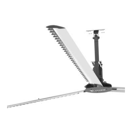
TRI-LITE HVLS SERIES
CEILING FANS
INSTALLATION INSTRUCTIONS /
BEFORE YOU BEGIN
FAN COMPONENTS
See Cable Detail
Drawing
TRI-LITE HVLS-M (04_29_15)
PLEASE READ AND SAVE THESE INSTRUCTIONS
Your kit should include all of the components shown below.
CABLE DETAIL
NOTE: HVLS blades are not
shown in the assembly to
allow greater detail of parts.
See Figure 14 for finished
assembly.
Page 1 of 13
Publicité
Table des Matières

Manuels Connexes pour Canarm TRI-LITE HVLS Serie


Sommaire des Matières pour Canarm TRI-LITE HVLS Serie
- Page 1 TRI-LITE HVLS SERIES CEILING FANS INSTALLATION INSTRUCTIONS / PLEASE READ AND SAVE THESE INSTRUCTIONS BEFORE YOU BEGIN Your kit should include all of the components shown below. FAN COMPONENTS CABLE DETAIL NOTE: HVLS blades are not shown in the assembly to allow greater detail of parts.
- Page 2 TRI-LITE HVLS SERIES FANS ELECTRICAL SAFETY WARNING! Ignoring the following instructions can cause physical injury or death, or damage to the equipment. ELECTRICAL HAZARD WARNING! Only qualified electricians are allowed to install the drive and connections to the motor! Never work on the drive, motor cable or motor when input power is applied. After disconnecting the input power, always wait for 5 minutes to let the intermediate circuit capacitors discharge before you start working on the drive, motor or motor cable.
- Page 3 DIFFERENT MOUNTING I BEAM MOUNTING APPLICATIONS NOTE: The following mounting applications are representations only and are subject to change without notice. Contact your Canarm sales representative for complete mounting instructions. OWSJ MOUNTING WOOD BEAM MOUNTING CONCRETE BEAM MOUNTING PURLIN “Z” MOUNTING...
-
Page 4: Standard Mount
TRI-LITE HVLS SERIES FANS STANDARD MOUNT FIGURE 1 A Standard Mount package is used with all Tri-Lite HVLS Fans assemblies (except “Wood” Beam Mounting). See Figure 1. Standard drop mounts of approximately 1’, 2’ and 4’ are available. The package includes: (2) mfg “I”... - Page 5 TRI-LITE HVLS SERIES FANS FIGURE 5 INSTALLING THE EXTENSION 1. Using a 7/8” wrench, fasten top plate of extension to the bottom plate of the standard mount using M14 bolts, nuts and washers. 2. Position the safety cable as per Figure 5, loop at both ends. 3.
- Page 6 TRI-LITE HVLS SERIES FANS GUY WIRES Extra hardware required: (4) Forged Eye Bolts M6-1.0 x 100mm The package includes: (4) Nuts M6-1.0 (4) Cable 3mm SS (66’ length provided to equal 4 @ 16.5’) (4) Nylocks Mg-1.0 (8) Thimbles 6mm SS (8) Washers Flat M6 (16) Cable Clamps 3mm I-Beam...
-
Page 7: Blade Assembly
TRI-LITE HVLS SERIES FANS INSTALLING GUY WIRES FIGURE 11 1. Determine mounting position on ceiling and establish the angle between 45˚ - 60˚ for the cable. Determine correct location on the I Beam to drill 5/16” diameter hole for the eye bolt. -
Page 8: Final Steps
TRI-LITE HVLS SERIES FANS FINAL STEPS FIGURE 14 IMPORTANT LEVELLING INSTRUCTIONS: After your fan is installed, check the level again by placing your level vertically on the side of the fan frame. If adjustment is needed slightly tighten the guy wire on the appropriate side. -
Page 9: Recommended Maintenance Schedule
8. A tailboard meeting shall be performed before any work is done. A checklist shall be completed and shall include any emergency contacts for the area. POWER UNIT Motor Our motor or gear motor manufacturers supply Canarm with gear motors built for our application. Designed for use with variable frequency drives. Maintenance Schedule Initial Six Months •... -
Page 10: Safety Precautions
Contractor is responsible for verifying all site conditions to include field dimensions where applicable. If the contractor elects to make any changes without notifying Canarm Ltd., the contractor is responsible for the same. All drawings are to be used as general architectural intent unless otherwise stamped. - Page 11 TRI-LITE HVLS SERIES FANS RECOMMENDED MAINTENANCE CHECKLIST Fan Size: ____________________ Fan Size: ____________________ Fan Size: ____________________ Serial #: _____________________ Serial #: _____________________ Serial #: _____________________ Location: ____________________ Location: ____________________ Location: ____________________ Date Initials Date Initials Date Initials TRI-LITE HVLS-M (04_29_15) Page 11 of 13...
-
Page 12: Limitation Of Warranty And Liability
1 year limited warranty Canarm Ltd. warrants that this product will, under normal use and service as specified by Canarm Ltd., operate properly and be free of defects in materials and workmanship for a period of one year from the date of purchase by customer. The term “operate properly” in this context applies to mechanical, electrical and structural functions only. - Page 13 7. Once the units have been changed over, submit all reasonable costs to Canarm Ltd. for payment. 8. No credits or cheques will be issued until all original products are received back at Canarm Ltd. or unless Canarm Ltd. directs otherwise.
- Page 14 VENTILATEURS DE PLAFOND TRI-LITE DE LA SÉRIE HVLS MODE D’INSTALLATION / LIRE ET CONSERVER CE DOCUMENT AVANT DE DÉBUTER Votre ensemble devrait inclure les items illustrés ci-dessous (1) Plaque de montage + (2) PIÈCES DU VENTILATEUR Plaques de cales + (2) Plaques de Retenue (4) Boulons M14-2.0 x 54mm Soutien structural du bâtiment...
-
Page 15: Sécurité Électrique
VENTILATEURS DE PLAFOND TRI-LITE DE LA SÉRIE HVLS SÉCURITÉ ÉLECTRIQUE MISE EN GARDE ! Ignorer les instructions de sécurité peut résulter en une blessure corporelle ou une mortalité ou ELECTRICAL HAZARD un dommage â l’équipement. MISE EN GARDE! Seul un électricien qualifié doit faire l’installation des entraînements et des connexions au moteur ! Ne pas travailler sur la transmission, le câble du moteur ou le moteur lorsque le cordon d’alimentation est sous tension. -
Page 16: Différentes Applications D'installation
D’INSTALLATION N.B. : Les divers applications d’installation suivantes ne sont que représentatives et sont sujets â changements sans préavis. Communiquer avec votre représentant Canarm pour obtenir les instructions d’installation complètes. INSTALLATION SUR POUTRELLE INSTALLATION SUR POUTRELLE EN BOIS AJOURÉE EN ACIER INSTALLATION SUR PURLIN EN Z INSTALLATION SUR POUTRELLE EN BÉTON... -
Page 17: Installation Standard
VENTILATEURS DE PLAFOND TRI-LITE DE LA SÉRIE HVLS INSTALLATION STANDARD ILLUSTRATION 1 Un ensemble d’installation standard doit être utilisé avec tous les ventilateurs Tri-Lite de la série HVLS (sauf dans le cas d’installation sur une poutrelle en bois) Voir l’illustration 1. Des ensembles d’installation de 1’, 2’... -
Page 18: Installation Des Extensions
VENTILATEURS DE PLAFOND TRI-LITE DE LA SÉRIE HVLS ILLUSTRATION 5 INSTALLATION DES EXTENSIONS 1. A l’aide d’une clé de 7/8’’ posez la plaque supérieure de l’extension à la plaque inférieure de la ferrure standard à l’aide des boulons M14, des écrous et des rondelles. 2. - Page 19 VENTILATEURS DE PLAFOND TRI-LITE DE LA SÉRIE HVLS FILS DE HAUBAN Quincaillerie additionnelle requise : Cet ensemble comprend : (4) boulons forgés à œillets M6-1.0 x 100mm (4) écrous M6-1.0 (4) câble en inoxydable de 3mm (longueur de 66’ compris pour égaler 4 @ 16.5’) (4) boulons nylock Mg-1.0 (8) guides en inoxydable 6mm (8) rondelles plates M6...
-
Page 20: Installation Des Fils De Hauban
VENTILATEURS DE PLAFOND TRI-LITE DE LA SÉRIE HVLS INSTALLATION DES FILS DE HAUBAN ILLUSTRATION 11 1. Déterminer la position de l'installation au plafond et établir un angle entre 45 et 60 degrés du câble. Déterminer l'emplacement exact sur la solive en I et percer un trou de 5/16'' pour le boulon à œillet. Par exemple, si le ventilateur est à... -
Page 21: Étapes Finales
VENTILATEURS DE PLAFOND TRI-LITE DE LA SÉRIE HVLS ÉTAPES FINALES ILLUSTRATION 14 INSTRUCTIONS IMPORTANTES SUR LE NIVELAGE : Après avoir installé votre ventilateur vérifier le niveau une fois de plus en plaçant le niveau verticalement sur le côté du cadrage du ventilateur. -
Page 22: Cédule D'entretien Recommandée
8. Une liste des personnes ou ressources à contacter en cas d'urgence sera établie par un comité et une liste de travaux sera établie avant le début des travaux d'entretien. UNITÉ DE POUVOIR Moteur Nos manufacturiers fournissent Canarm de moteurs à engrenages fabriqués spécialement pour notre application. Conçu pour usage avec entraînement à fréquence variable. Cédule d'entretien Premier six mois •... -
Page 23: Cédule D'entretien Suite
Le contracteur est responsable pour la vérification du site d’installation ou applicable. Si le contracteur décide de faire quelques changements sans avertir Canarm Ltée. Le contracteur sera responsable pour ces changements. Tous les dessins serviront pour fins d’architecture générale à moins d’être estampés autrement. -
Page 24: Liste De Vérification Des Entretiens Recommandés
VENTILATEURS DE PLAFOND TRI-LITE DE LA SÉRIE HVLS LISTE DE VÉRIFICATION DES ENTRETIENS RECOMMANDÉS Diamètre du ventilateur: ___________ Diamètre du ventilateur: ___________ Diamètre du ventilateur: ___________ # Série : ___________________________ # Série : ___________________________ # Série : ___________________________ Endroit : __________________________ Endroit : __________________________ Endroit : ___________________________ Date... -
Page 25: Limites De La Garantie Et De La Responsabilité
1 an Canarm Ltée. garantie que ce produit, avec un usage et entretien normaux tels que spécifiés par Canarm Ltée., opérera correctement et sera libre de toutes défectuosités dans les matériaux et dans la main d’œuvre pour une période d’un an à compter de la date d’achat par le client. -
Page 26: Limites De La Garantie Et Resposabilité
Si le fabriquant détermine qu’il n’y a pas de défectuosité et refuse de couvrir le problème sous la garantie, Canarm Ltée. fera de même et ne couvrira pas le problème sous la présente garantie à moins qu’il est déterminé que le problème provient d’une défectuosité...