Table des Matières
Publicité
Les langues disponibles
Les langues disponibles
Liens rapides
Publicité
Chapitres
Table des Matières

Manuels Connexes pour Belmash SDM-2000

Sommaire des Matières pour Belmash SDM-2000
- Page 3 Images Contenu Certificat d'acceptation Afbeeldingen Inleiding Goedkeuringscertificaat Figures Contents Approval certificate...
- Page 4 2а 57а 28 27...
- Page 5 32 30a 2а 5 mm min Вид B Вид А Вид C Вид D Вид D Вариант 1 Вариант 2...
- Page 6 73а...
- Page 7 Вид A 68а...
- Page 8 26 49 45 47...
- Page 9 3с 3u 3r 11a 11b...
- Page 11 12 57а...
-
Page 12: Table Des Matières
CONTENU Introduction 1. Déclaration de conformité ЕС/ЕЕА 2. Désignation 3. Vue d’ensemble 4. Paramètres principaux 5. Trousse de livraison 6. Eléments de base 7. Prescriptions de prévention des accidents 8. Marquage et emballage 9. Structure de machine-outil 10. Procédures de prestation 11. -
Page 13: Déclaration De Conformité Ес/Ееа
** — pour les machines-outils BELMASH SDM-2200, BELMASH SDM-2500 Directeur ________________ D.V. Shorikov Les certificats de conformité sont gardés à l’adresse suivante: Société solidaire à responsabilité limitée « Usine Belmash », Slavgorodskiy proezd, 37 La République du Bélarus, 212000, la ville de Moguilev. -
Page 14: Désignation
L’alimentation de la machine-outil se fait d’un réseau monophasé du courant alternatif avec un conducteur protecteur (de terre). Les machines-outils BELMASH SDM-2200 et BELMASH SDM-2500 doivent être exploitées au réseau électrique avec une impédance absolue conditionnelle z =0,354 ohm. L’usager doit s’assurer de la conformité... -
Page 15: Paramètres Principaux
Les paramètres principaux sont indiqués sur le tableau 1. Tableau 1 Paramètres № Dénomination BELMASH BELMASH BELMASH SDM-2000 SDM-2200 SDM-2500 Largeur maximale de rabotage, mm Echelle de profondeur de rabotage, mm 0÷3 0÷3 0÷3 Epaisseur maximale de préforme, pendant le rabotage avec un dispositif presseur, pas plus, mm Diamètre nominal de lame de scie, mm... -
Page 16: Trousse De Livraison
Trousse de livraison est indiqué sur le tableau 2. Tableau 2 Quantité (piéces) № Position, image Nom de trousse BELMASH BELMASH BELMASH SDM-2000 SDM-2200 SDM-2500 Mécanismes, dispositifs, clôtures Machine-outil Image 1, 2 multifonctionnelle du bois Clôture de lame de scie et Position 2, 2а,... - Page 17 Position 33, image 1 Boîtier Position 16, image 1 Barre poussoir Articles normalisés Lame de scie 18** Position 32, image 1 Ø 250×3,2/1,8×30 mm 24Т Lame de scie Position 32, image 1 Ø 280×3,2/2,2×30 mm 24Т Lame de scie Position 32, image 1 Ø...
-
Page 18: Eléments De Base
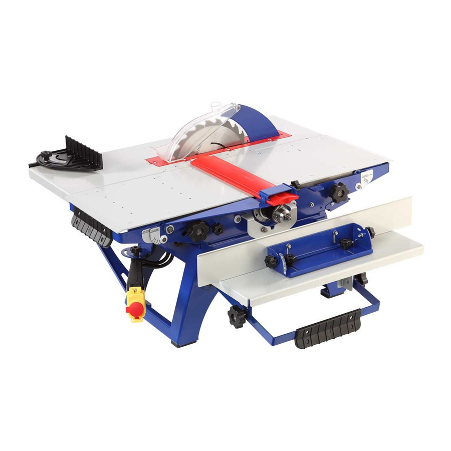
6. ELEMENTS DE BASE Image 1 1 – corps de machine-outil 22 – bouton de réglage de profondeur de 2 – clôture de lame de scie découpe 2а – couteau diviseur 23 – table à scie 3с – guidage longitudinal 30 –... -
Page 19: Prescriptions De Prévention Des Accidents
7. PRESCRIPTIONS DE PREVENTION DES ACCIDENTS Avant de commencer le travail étudiez bien les exigences de sécurité . Suivez toutes les recommandations de ce manuel d’instruction. En commençant le travail avec la machine-outil l’usager doit tenir compte de sa condition physique, du niveau de préparation et la complexité... -
Page 20: Exigences Au Lieu De Travail
7.1. Exigences au lieu de travail Le lieu de travail doit être choisi compte tenu la disposition des matières d’œuvre et des produits terminés, la direction de leur déplacement et le lieu de la collection de déchets. ● l’espace du périmètre des tables de travail de la machine-outil doit être spacieux à une distance au moins d’un mètre pour son entretien. -
Page 21: Exigences Pour Les Matières D'œuvre
La durée totale de la présence dans la zone d'exploitation sans équipement de protection auditive individuelle ne doit pas dépasser 4,8 heures. Assurez un stockage sécurisé de la machine-outil. Gardez-la aux endroits secs et inaccessibles aux enfants. En cas de dysfonctionnement, la machine-outil doit être réparée par un personnel qualifié avec l'utilisation des pièces de rechange d'origine. - Page 22 par le fabricant. Lorsque vous travaillez, tenez compte des dimensions maximales du traitement. L’information sur les types de traitement est présentée sur l'étiquette de la clôture 57 de la lame de scie au-dessous du niveau de la table. Sur le panneau de commande rotatif 62 (image 2) il y a une étiquette avec des avertissements sur les dangers.
-
Page 23: Structure De Machine-Outil
9. STRUCTURE DE MACHINE-OUTIL La machine-outil représente un dispositif électromécanique piloté par un moteur asynchrone. La rotation est transmise du moteur au bloc de coupe (extrémité du rouleau de sortie) et à la lame de scie avec le lecteur de courroie trapézoïdale. La courroie 81 est en boucle sur une roue motrice et deux poulies entraînées (image 26). -
Page 24: Assemblage Et Montage D'une Clôture Combinée
dispositifs et les clôtures qui forment une trousse. ● Ajuster l'insert de la lame de scie (sous-point 10.1.1); ● Monter la clôture de la lame de scie avec un couteau diviseur (sous-point 10.1.2); ● Monter la clôture combinée (sous-point 10.1.3); ●... -
Page 25: Montage De La Clôture D'arbre De Coupe Avec Support
La hauteur recommandée des tables de travail de la machine-outil est de 850÷950 mm du niveau du sol. “Usine Belmash” produit des supports BELMASH P-2 et BELMASH PK-2 et le plateau de table BELMASH ST pour le montage de la machine-outil. Des informations détaillées sont disponibles sur www.belmash.by. -
Page 26: Conditions D'utilisation Normale De La Machine-Outil
panneau de commande pouvant être tourné avec le commutateur est placé dans une zone de travail accessible à gauche de la table de chargement 25; ● la deuxième - pour fonctionner en mode fraisage. Le panneau de commande pouvant être tourné avec le commutateur est tourné et réglé en pleine position droite dans une zone accessible au travail. -
Page 27: Utilisation De Clôture
● desserrer la vis 45 de la table de chargement 25; ● régler la table de chargement à la profondeur de rabotage requise (0÷3 mm) en haut / en bas en déplaçant la poignée de levier 46 en se basant dessous la table et en faisant correspondre l'alignement 47 de la table de chargement avec la valeur requise de l'échelle 48 (image 11) ;... -
Page 28: Montage De La Table De Scie
Réglez la clôture combinée comme cela est indiqué sur l’image 12. La clôture de guidage 3f peut être réglée perpendiculairement ou sous un angle de la table. Pour régler le guidage de clôture 3f sous un angle, desserrez les deux vis à oreilles 3g, mettez la clôture à... -
Page 29: Montage De Fraisage D'extrémité Et De Forage
● monter la fraise à l'extrémité ou la perceuse; ● monter la table de fraise 10 (image 20); ● monter le support 5. 11.4.1 Montage de fraisage d’extrémité et de forage Afin d’installer le fraisage d’extrémité et de forage, faites des procédures suivantes: ●... -
Page 30: Montage De Clôture
(image 1). 11.6. Utilisation des pièces jointes supplémentaires Pour les machines-outils BELMASH SDM-2000, BELMASH SDM-2200, BELMASH SDM-2500, il existe une gamme de pièces jointes supplémentaires qui étendent la fonctionnalité des machines-outils, telles que les attaches de la raboteuse TD-2000, TD-2200, TD-2500, le dispositif de fraisage MD -01, porte latérale SC-01. -
Page 31: Affûtage Et Remplacement Des Couteaux De Rabotage
12.1 Affûtage et remplacement des couteaux de rabotage Il est nécessaire d'affûter ou de remplacer périodiquement les couteaux de rabotage (image 23) lorsqu'ils sont brusques. Le tranchant du couteau doit être pointu et exempte de déformations, d'indentations, de sillons et de fissures. Pour remplacer et monter les couteaux, faites des procédures suivantes: ●... -
Page 32: Remplacement De La Courroie De Transmission
de scie 32 ou le disque de coupe 12 à la position inférieure (de transport). ● Dévisser la vis à oreilles de réglage de la profondeur de la coupe 54. ● Retirer l'écrou de serrage 79 et la lame de scie 32 ou le disque de coupe 12. 12.3 Remplacement de la courroie de transmission Pour remplacer la courroie de transmission, faites des procédures suivantes: ●... -
Page 33: Protection De L'environnement
15. PROTECTION DE L’ENVIRONNEMENT Les pièces de machine-outil en plastique sont correctement marquées, ce qui permet de faire leur séparation et leur recyclage. Les pièces et les dispositifs usés de la machine-outil doivent subir un recyclage respectueux de l'environnement. 16. TRANSPORT Le transport des machines-outils se fait dans des véhicules fermés. - Page 34 INHOUD Inleiding 1. EU-conformiteitsverklaring 2. Gebruik 3. Algemeen informatie 4. De belangrijkste parameters 5. Verpakkinginhoud 6. Basiselementen 7. Veiligheideisen 8. Markering en verpakking 9. Arrangement de machine 10. Prestatiewerkzaamheden 11. Basisbediening 12. Technische onderhoud en reparatie 13. Storingen verhelpen 14. Voorzorgsmaatregelen bij opslag 15.
- Page 35 * voor de machine BELMASH SDM-2000; ** voor machines BELMASH SDM-2200, BELMASH SDM-2500 Directeur _________________ D. V. Shorikov De certificaten van overeenstemming worden gehouden op het volgende adres: " Belmash Fabriek" BVBA, 37 Slavgorod passage, Mogilev stad, 212000, Republiek Belarus.
-
Page 36: Gebruik
De kracht van de machine is uitgevoerd van monophase netwerk van wisselstroom met een beschermend (aarding) draad. Machines BELMASH SDM-2200 en BELMASH SDM-2500 moet worden gebruikt in netwerken met een nominale impedantie z =0,354 Оhm. De operator moet ervoor zorgen dat de nominale laadcapaciteit van de stroomlijn geschikt is. -
Page 37: De Belangrijkste Parameters
4.DE BELANGRIJKSTE PARAMETRS De belangrijkste parameters staan vermeld in tabel 1. Tabel 1 Parameters № BELMASH BELMASH BELMASH Naam SDM-2000 SDM-2200 SDM-2500 Maximale schaafbreedte, mm Bereik van schaafdiepte, mm 0÷3 0÷3 0÷3 Maximale dikte van het werkstuk bij het schaven met spaninrichting, niet meer, mm... -
Page 38: Verpakkinginhoud
Verpakkinginhoud zijn vermeld in tabel 2. Tabel 2 Hoeveelheid (stuks) № Item, afbeelding Naam van de items BELMASH BELMASH BELMASH SDM-2000 SDM-2200 SDM-2500 Mechanisms, attachments, guards Multifunctionele Afbeelding 1, 2 houtbewerkingsmachine Item 2, 2а, Hek met splijtblad voor afbeelding 1, 2... - Page 39 Item 16, afbeelding 1 Stamper Standard items Cirkelzaagblad Item 32, afbeelding 1 Ø 250×3,2/1,8×30 mm 24Т Cirkelzaagblad Item 32, afbeelding 1 Ø 280×3,2/2,2×30 mm 24Т Cirkelzaagblad Item 32, afbeelding 1 Ø 315×3,2/2,2×30 mm 24Т afbeelding 23 Planer mes 230×2×20 mm afbeelding 23 Planer mes 250×2×20 mm afbeelding 23...
-
Page 40: Basiselementen
6. BASISELEMENEN Afbeelding 1 1 – machinelichaam 22 – blade depth adjustment handle 2 – zaagblad guard 23 – zaagtafel 2а – splijtblad 30 – zaagtafel plastic inlage 3с – longitudinale cross slide 31 – ringen and moer 3d – cross slide 33 –... -
Page 41: Veiligheideisen
7.VEILIGHEIDEISEN Voor de operatie, de studie van de veiligheidseisen. Volg alle voorschriften van handleiding. Aan de slag op het apparaat moet u rekening houden met uw fysieke toestand van het trainingsniveau en de complexiteit van de uitgevoerde taken. Om op de machine te werken, zijn personen ouder dan 18 jaar die deze handleiding hebben bestudeerd. - Page 42 het richten, voeren en verwijderen van werkstuk, rekening houdend met de totale afmetingen en het gewicht ervan; ● de vloer mag niet glad zijn en obstakels hebben; ● de machine en de werkplek moeten schoon gehouden worden; ● de werkplek moet goed verlicht zijn met natuurlijke of kunstmatige lichtbronnen; houd er rekening mee dat het gebruik van fluorescerende verlichting een stroboscoop effect veroorzaakt, wat kan leiden tot een onjuiste bepaling van de roterende richting van de bewegende delen van de machine;...
-
Page 43: Markering En Verpakking
7.4 Werkstukeisen Het gewicht van een lege wordt verwerkt mag niet meer dan 50 kg. Bij het verwerken blanks meer dan 2 m, is het noodzakelijk om ondersteuning gemonteerd onder het overhangende uiteinde van de plano gebruiken of in tandem. Minimale hoogte van een blanco voor het zagen en frezen - 5 mm. -
Page 44: Arrangement De Machine
Niet aanraken, houd uw handen uit de buurt. Bij contact met de tool is er een risico van letsel. Draag eenwegwerpmasker. Draag een oorbescherming. Draag een veiligheidsbril. Gooi elektrische gereedschappen huishoudelijk afval. overeenstemming met de Europese Richtlijn 2002/96/EG, afgedankte elektrische en elektronische apparatuur moet gescheiden te worden ingezameld en te doneren aan milieuvriendelijke recycling. -
Page 45: Machine Assemblage
planktafels (afbeelding 2). Schaaftafels die in zaagmodus worden gebruikt, implementeren de zaagtafel. De uitlaat- en laadtafels die worden gebruikt in de schaafmodus worden gemonteerd op het niveau van de schaaf messen snijden, terwijl de laadtafel een mogelijkheid heeft om te worden verlaagd onder het niveau van schaaf messen snijden en zorgt voor het instellen van de benodigde schaafdiepte. - Page 46 10.1.2 Montage van zaagbladguard met splijtblad Om het splijtblad 2a (afbeelding 4) op de machine te monteren is het nodig om het uiteinde ervan met veegleuf door de uitsparing van het inzetstuk te passeren en deze over twee schroefdraadstangen te steken, zodat de sweepslot zich bevindt tussen tussenringen en moeren die eerder op de schroefdraad zijn gemonteerd staven.
-
Page 47: Machine Starten
Het is aan te raden om de machine te repareren met boutverbinding. Aanbevolen hoogte van werktafels van de machine is 850-950 mm van de vloer. Om de machine te installeren produceert "Belmash Fabriek” staanders BELMASH P-2 en BELMASH PK-2 ondersteunt en werkbladen BELMASH ST. Gedetailleerde informatie is beschikbaar op www.belmash.by. -
Page 48: Basisbediening
hardheid bij maximale breedte en diepte en handmatig vullen van lege in bewerkingspunt, in een enkele doorgang: bij het schaven - 1,5 m / min, bij het zagen - 1 m / min. 11. BASISBEDIENING 11.1 Oppervlakte planken, kantelen en hoekplanken (randplanken) ●... - Page 49 Assemblage en montage van de gecombineerde hek zijn in subpost 10.1.3. Stel de geleidingshek 3f en de plaat 3s zoals weergegeven op afbeelding 12. De geleidingshek 3f kan loodrecht of op een hoek naar de tafel worden ingesteld. Om de geleidingshek 3f in een hoek te zetten, los de twee duimschroeven 3g los, stel de hek in de gewenste hoek met behulp van de schaal 51, draai de duimschroeven 3g aan.
-
Page 50: Routertafel Montage En Afstelling
door de bekistingspanner 54 aan te draaien. Als u de geleidingshek 3f gebruikt tijdens zaagwerkzaamheden, plaatst u de plaat 3s volgens afbeelding 16. Afbeelding 17. Machine regeling in zagen modus met de geleidingshek gemonteerd aan de linkerkant van het zaagblad. 11.3 Het zagen aan de overkant van de korrel op een hoek met een bijlage. -
Page 51: Guard Montage
Freesdiepte van dics snijder is ingesteld op dezelfde manier als het zaagblad diepte (subpost 11.2.2). Freesdiepte schaal 61 ligt rechts van het zaagblad behuizing 57 (afbeelding 1). 11.6. Extrabijlagengebruik Voor de machines BELMASH SDM-2000, BELMASH SDM-2200, BELMASH SDM-2500 beschikbaar er aanvullende bijlagen zich uitstrekken functionaliteit van de machines, zoals... -
Page 52: Technische Onderhoud En Reparatie
SC-01. De apparaten zijn niet inbegrepen in een standaard pakketset. Gedetailleerde informatie en handleidingen voor alle andere apparaten beschikbaar op www.belmash.by. 12. TECHNISCHE ONDERHOUD EN REPARATIE Om het handhaven van de machine in een permanente technische staat en bereid zijn te werken, hebben we eenelke shift technische onderhoud - TS. -
Page 53: Storingen Verhelpen
instelling handvat 28 (afbeelding 1), zoals weergegeven in afbeelding 25. ● Los de bladdiepteverstelling duimmoer 54 van het zaagblad 32 of schijfmes 12 los. ● Verwijder de behuizing 57 van het zaagblad of schijfmes (afbeelding 1) met een schroevendraaier. ● Plaats de duimmoer 54 van de bladdiepte in zijn plaats. ●... -
Page 54: Voorzorgsmaatregelen Bij Opslag
14. VOORZORGSMAATREGELEN BIJ OPSLAG Machines die ontworpen zijn voor de opslag in gesloten of op andere plaatsen met natuurlijke ventilatie zonder kunstmatig gecontroleerde klimatologische omstandigheden waar schommelingen van temperatuur en luchtvochtigheid aanzienlijk minder dan in de open lucht (bijvoorbeeld, steen, beton, metaal -, isolatie-en andere niet-verwarmde opslag, gelegen in gebieden met gematigde en koude klimaat). - Page 55 CONTENTS Introduction 1. Declaration of conformity ЕС/ЕЕА 2. Intended use 3. General information 4. Main parameters 5. Package contents 6. Basic elements 7. Safety requirements 8. Marking and packing 9. Machine unit arrangement 10. Prestarting procedures 11. Basic operations 12. Technical maintenance and repair 13.
-
Page 56: Declaration Of Conformity Ес/Ееа
1. DECLARATION OF CONFORMITY ЕС/ЕЕА Joint limited liability company “Zavod Belmash” declares that multifunctional woodworking machines BELMASH SDM-2000 BELMASH SDM-2200... -
Page 57: Intended Use
The power of the machine is supplied by a single-phase AC with an earthed positive earth. BELMASH SDM-2200, BELMASH SDM-2500 machines shall be used in the electrical grids with a nominal impedance z =0,354 ohm. -
Page 58: Main Parameters
Main parameters are specified in the Table 1. Table 1 Parameters № Name BELMASH BELMASH BELMASH SDM-2000 SDM-2200 SDM-2500 Max. planing width per pass, mm Range of planing depth per pass, mm 0÷3 0÷3 0÷3 Max. height of the work piece pressed by a holding... -
Page 59: Package Contents
5. PACKAGE CONTENTS Table 2 Quantity (pieces) № Item Name of items BELMASH BELMASH BELMASH SDM-2000 SDM-2200 SDM-2500 Mechanisms, attachments, guards Figure 1, 2 Multifunctional woodworking machine Item 2, 2а, Guard with splitting blade for circular saw blade and disk cutter... - Page 60 Standard items Circular saw blade 250×3,2/1,8×30 Item 32, figure 1 mm 24Т Circular saw blade 280×3,2/2,2×30 Item 32, figure 1 mm 24Т Circular saw blade 315×3,2/2,2×30 Item 32, figure 1 mm 24Т figure 23 Planer knife 230×2×20 mm figure 23 Planer knife 250×2×20 mm figure 23 Planer knife 270×2×20 mm...
-
Page 61: Basic Elements
6. BASIC ELEMENTS Figure 1 1 – machine body 16 – pusher 2 – circular saw blade guard 22 – blade depth adjustment handle 2а – splitting blade 23 – saw table 3с – longitudinal slide 30 – saw table plastic insert 3d –... -
Page 62: Safety Requirements
7. SAFETY REQUIREMENTS Before operation, study the safety requirements. Follow all the requirements of the present manual. Getting started the machine usage, operator should consider his physical condition, level of qualification and complexity of the tasks performed. Machine operation is allowed only for personnel of 18-year age or older having studied the present operating manual. - Page 63 and take away considering their weight and dimensions; ● floor should not be slippery and have obstacles; ● the machine and workplace should be kept clean; ● workplace should be well illuminated with natural or artificial light sources; please note that the usage of fluorescent lighting causes a stroboscopic effect which may lead to incorrect determination of rotating direction of machine’s moving parts;...
-
Page 64: Marking And Packing
or other flaws in the wood. During cross-cutting of round timber, supply the blank by moving it over the table surface, not by rolling. Blanks should not be moist. The recommended moisture content is not more than 22%. 7.5 Working stance and blank supply The correct working stance of the operator is standing position. -
Page 65: Machine Unit Arrangement
Use a dust mask. Always wear personal protection equipment to prevent hearing damage. The noise exposure can cause permanent hearing loss. Wear eye-protection goggles. Never dispose this tool together with unsorted municipal waste. In accordance with the European Directive 2002/96/EC on waste electrical and electronic equipment and its implementation into national law, nonfunctioning power tools must be collected separately and recycled in an environmentally suitable manner. -
Page 66: Prestarting Procedures
providing safe operation. Tables are moved with built-in handle-levers. This arrangement allows fast and easy setting the machine for a necessary processing type. The machine’s switch 50 (figure 1) with a special system for accidental turning on protection is mounted on turnable bracket designed to provide accessible and safe ON/OFF switching. For the blank orientation against the cutting device and to provide its linear, straight and longitudinal movement, the machine is equipped with a combined fence with turnable bracket. - Page 67 It’s recommended to fix the machine with bolted connection. Recommended height of the machine’s working tables is 850-950 mm from floor level. “Zavod Belmash” produces BELMASH P-2 and BELMASH PK-2 supports and BELMASH ST table board for the machine mounting. Detailed information is available on www.belmash.by.
-
Page 68: Basic Operations
state (figure 7) using the hexagon wrench. Figure 8. Knives fixing: 73 – cutter-block; 73а – chip-breaker groove; 74 – knife; 75 – clamping plate; 76 – clamp screw. Figure 9. Adjustment device: 73 – cutter-block; 74 – knife; 75 – clamping plate; 77 – adjustment screw. - Page 69 11.1.1 Planing tables mounting To mount the planing tables, perform the following (figure 6): ● loosen thumb nuts 26 and 45; ● pull the locking clamp 28 (horizontally), holding it from the bottom and lower the tables by moving the handle-levers 46 and 49; ●...
- Page 70 Preparation and adjustment includes: ● tables setting; ● blade depth setting. Set the combined fence as displayed on figure 12. The guide fence 3f can be set perpendicular or at an angle to the table. To set the guide fence 3f at an angle, loosen the two thumbscrews 3g, set the fence to the required angle using the scale 51, tighten the thumbscrews 3g.
- Page 71 11.4.1 End milling cutter or drill mounting To mount the end milling cutter or the drill, perform the following: ● join and mount the planing tables at the level of saw table according to sub-item 11.2.1; ● lower the saw blade 32 to the bottom “min” position on the blade depth scale 60 (figure 1);...
-
Page 72: Technical Maintenance And Repair
Milling depth scale 61 is located to the right on the saw blade casing 57 (figure 1). 11.6. Additional attachments usage For the machines BELMASH SDM-2000, BELMASH SDM-2200, BELMASH SDM-2500 there available a range of additional attachments extending the machines’ functionality, such as thicknessing planer attachments TD-2000, TD-2200, TD-2500, milling device MD-01, side holder SC-01. - Page 73 weight difference adapting is performed by metal removal from a knife edges. Adjust the knives according to sub-item 10.3. In case of replacement (adjustment) of plane knives, before unscrewing the screws settle them (impact on the head of the screw with a hammer through hexagonal stick) in order to preserve integrity of screws and threads of the plane shaft (fig.
-
Page 74: Troubleshooting
13. TROUBLESHOOTING Possible malfunctions and ways of their detection and elimination are listed in the table 3. Table 3 Name of malfunction Possible reason Way of elimination and its signs Check the power line voltage with any No voltage in power line other obviously working device The powered ON machine No contact between the socket and...