Table des Matières
Publicité
Les langues disponibles
Les langues disponibles
Liens rapides
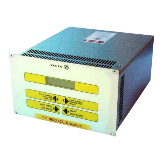
Turbo-V 1000 ICE
E-series Controller
Model 969-9464
Model 969-9564
87-900-951-01 (B)
APRIL 2002
vacuum technologies
MANUALE ISTRUZIONI
BEDIENUNGSHANDBUCH
NOTICE DE MODE D'EMPLOI
MANUAL DE INSTRUCCIONES
MANUAL DE INSTRUÇÕES
BEDRIJFSHANDLEIDING
ISTRUKSTIONSBOG
BRUKSANVISNING
INSTRUKSJON MANUAL
OHJEKÄSIKIRJA
Ο∆ΗΓΙΕΣ ΧΡΗΣΕΩΣ
INSTRUCTION MANUAL
Publicité
Table des Matières

Manuels Connexes pour Varian Turbo-V 1000 ICE E Série


Sommaire des Matières pour Varian Turbo-V 1000 ICE E Série
- Page 1 vacuum technologies MANUALE ISTRUZIONI Turbo-V 1000 ICE BEDIENUNGSHANDBUCH E-series Controller NOTICE DE MODE D’EMPLOI MANUAL DE INSTRUCCIONES Model 969-9464 MANUAL DE INSTRUÇÕES Model 969-9564 BEDRIJFSHANDLEIDING ISTRUKSTIONSBOG BRUKSANVISNING INSTRUKSJON MANUAL OHJEKÄSIKIRJA Ο∆ΗΓΙΕΣ ΧΡΗΣΕΩΣ INSTRUCTION MANUAL 87-900-951-01 (B) APRIL 2002...
- Page 2 Turbo-V 1000 ICE E-series Controller...
-
Page 5: Table Des Matières
ISTRUZIONI PER L’USO ....................GEBRAUCHSANLEITUNG ................... MODE D’EMPLOI ......................INSTRUCCIONES DE USO ................... INSTRUÇÕES PARA O USO ..................17 GEBRUIKSAANWIJZINGEN ..................BRUGSANVISNING ...................... BRUKSANVISNING ...................... BRUKERVEILEDNING ....................KÄYTTÖOHJEET ......................ODHGIES CRHSEWS..................... INSTRUCTIONS FOR USE ................... TECHNICAL INFORMATION ..................TURBO-V 1000 ICE E-SERIES CONTROLLER DESCRIPTION ........... CONTROLLER SPECIFICATIONS .................... - Page 6 USE ..............................General ..........................Startup ........................... Front/Remote/Serial Selection ....................Starting the Pump ......................... Monitor Relay Programming ....................Pump Shutdown ........................Power Failure ........................Operating the Pump....................... Remote Control Mode Operation ..................RS 232/422/485 Control Mode Operation ................ACCESSORIES AND SPARE PARTS ................... OPTIONS ............................
-
Page 7: Informazioni Generali
L’utilizzo dell’apparecchiatura. Informazioni dettagliate sono fornite nell’appendice "Technical Information". Imballo dei controllers Questo manuale utilizza le seguenti convenzioni: Ogni controller è fornito dalla Varian predisposto per una certa tensione di alimentazione: PERICOLO! • il modello 969-9464 per 220 Vac... -
Page 8: Comandi, Indicatori E Connettori Del Controller
ISTRUZIONI PER L’USO INSTALLAZIONE NOTA Il connettore di richiusura J1 deve essere lasciato collegato con il suo ponticello se non viene effettuato PERICOLO! alcun collegamento esterno. La pompa di pre-vuoto e pompa Turbo-V possono essere accese II controller è fornito di un cavo di alimentazione a tre contemporaneamente. -
Page 9: Procedure Di Uso
Pannello posteriore dei controller 969-9464 e 969-9564 In caso di guasto è possibile usufruire del servizio di PROCEDURE DI USO riparazione Varian o del "Varian advanced exchange service", che permette di ottenere un controller Accensione del Controller rigenerato in sostituzione di quello guasto. - Page 10 Se il messaggio si ripresenta rivolgersi alla spurio. Varian per la manutenzione. Allarme relativo al flusso di purge. Il Controllare il corretto funzionamento del FLOW METER ALARM valore del flusso è rimasto ad un valore circuito di alimentazione del gas.
-
Page 11: Vor Der Installation
Personal, nicht autorisierten (nicht kondensierend) Eingriffen und Mißachtung der einheimischen, hier zur Geltung kommenden Bestimmungen übernimmt die Firma Varian keinerlei Haftung. Die Controller der Serie VOR DER INSTALLATION Turbo-V 1000 ICE E-series sind mikroprozessor- Controller wird einer speziellen gesteuerte Frequenzwandler. - Page 12 GEBRAUCHSANLEITUNG INSTALLATION ANMERKUNG Der Wiederverschließ-Verbinder J1 muß mit seiner GEFAHR! Brücke angeschlossen bleiben, wenn kein externer Anschluß erfolgt. Die Vorvakuumpumpe und die Turbo- Der Controller wird mit einem Netzkabel geliefert, das 3 V-Pumpe können gleichzeitig eingeschaltet werden. Drähte enthält und mit einem den internationalen Normen entsprechenden Stecker ausgerüstet ist.
-
Page 13: Bedienung
10. Steckverbinder für Anschlußkabel zum Durchfluß- messer (flow meter). 11. Erdungsanschluß. Rückseitige Tafel der Controller 969-9464 und 969-9564 Bei einem Defekt kann der Varian-Reparaturdienst bzw. der "Varian advanced exchange service" in Anspruch genommen werden, der für die Erneuerung defekter BEDIENUNG Controller sorgt. - Page 14 Die Taste START zweimal drücken, um die OVERVOLTAGE eine Störung aufgetreten oder der Pumpe wieder anzufahren. Kontroller hat ein unechtes Signal Falls die Meldung nochmals auftritt, die empfangen. Firma Varian zur Instandsetzung zu Rate ziehen. Alarm hinsichtlich Auswurffluß. Einwandfreien Betrieb des FLOW METER ALARM Flußwert befindet sich für die Dauer von...
-
Page 15: Indications Generales
Des renseignements plus détaillés se trouvent dans l'appendice "Technical Emballage des contrôleurs Information". Cette notice utilise les signes conventionnels Chaque contrôleur est fourni par Varian pré-équipé pour suivants: une certaine tension d'alimentation: • le modèle 969-9464 pour 220 Vca DANGER! •... -
Page 16: Commandes, Indicateurs Et Connecteurs Du Contrôleur
MODE D'EMPLOI INSTALLATION NOTE DANGER! Laisser le connecteur de réenclenchement J1 connecté à sa barrette s'il n'est procédé à aucune connexion exté- Les contrôleur est doté d'un câble d'alimentation à trois rieure. La pompe à pré-vide et la pompe Turbo-V peu- fils avec une fiche du type approuvé... -
Page 17: Procedures D'utilisation
Tableau arrière des Contrôleurs 969-9464 et 969-9564 En cas de panne, il est possible de s'adresser au Servi- PROCEDURES D'UTILISATION ce de réparation Varian ou bien au "Varian advance exchange service" qui permet d'obtenir un contrôleur Allumage du Contrôleur régénéré à la place du contrôleur détraqué. - Page 18 Si le message est réaffiché vous adres- ser à la société Varian pour l’entretien. Alarme concernant le flux de purge. La Vérifier le bon fonctionnement du circuit FLOW METER ALARM valeur du flux est restée au dessous du...
-
Page 19: Información General
El usuario deberá leer atentamente el presente manual controlers se deberá cumplir con las condiciones instrucciones cualquier otra información ambientales siguientes: • suplementaria facilitada por Varian antes de utilizar el temperatura: de -20 °C a +70 °C • equipo. Varian considera libre cualquier... -
Page 20: Mandos, Indicadores Y Conectores Del Controler
INSTRUCCIONES DE USO INSTALACIÓN NOTA ¡PELIGRO! El conector di cierre J1 ha de dejarse conectado con su conector puente si no se efectúa ninguna conexión El controler va dotado de un cable de alimentación de exterior. La bomba pre-vacío y la bomba Turbo-V tres hilos con una clavija de tipo aprobado a nivel pueden encenderse simultáneamente. -
Page 21: Procedimientos De Uso
Panel trasero del controler 969-9464 y 969-9564 En caso de avería es posible utilizar el servicio de PROCEDIMIENTOS DE USO reparación Varian o del “Varian advance exchange service”, que permite obtener un controler regenerado Encendido del controler en vez del averiado. - Page 22 En caso el mensaje vuelva a aparecer, llamar a Varian para la manutención. Alarma concerniente flujo Controlar el correcto funcionamiento del FLOW METER ALARM limpieza (purge).
-
Page 23: Informações Gerais
• pela Varian antes de utilizar a aparelhagem. A Varian temperatura: de -20 ºC a + 70 ºC • não se responsabiliza pela inobservância total ou humidade relativa: 0 - 95% (não condensante) parcial das instruções, pelo uso indevido por parte de... -
Page 24: Instalação
INSTRUÇÕES PARA O USO INSTALAÇÃO NOTA ¡PERIGO! O conector de fecho J1 deve permanecer ligado à sua ponte se não é efectuada nenhuma ligação externa. A O controller é fornecido com um cabo de alimentação bomba de pré-vácuo e a bomba Turbo-V podem ser de três fios com uma tomada de tipo aprovado a nível ligadas simultaneamente. -
Page 25: Procedimentos De Uso
Painel posterior dos Controllers 969-9464 e 969-9564 Em caso de defeito é possível utilizar o serviço de PROCEDIMENTOS DE USO reparação Varian ou o "Varian advanced exchange service", que permite obter um controller regenerado Acendimento do Controller que substitua o controller com defeito. - Page 26 Se a mensagem se reapresenta, dirigir- se à Varian para a manutenção. Alarme relativo ao fluxo de descarga. O Verificar se o circuito de alimentação do FLOW METER ALARM valor do fluxo permaneceu num valor gás funciona correctamente.
-
Page 27: Algemene Informatie
• informatie door te lezen alvorens het apparaat in gebruik relatieve vochtigheid: 0 - 95% (niet condenserend) te nemen. Varian acht zich niet aansprakelijk voor de gevolgen van het niet of gedeeltelijk in acht nemen van VOORBEREIDING VOOR INSTALLATIE de aanwijzingen, onoordeelkundig gebruik door niet... -
Page 28: Installatie
GEBRUIKSAANWIJZINGEN INSTALLATIE OPMERKING De connector J1 moet met zijn jumper aangesloten GEVAAR! blijven als geen externe aansluiting tot stand wordt gebracht. De pre-vacuümpomp en de Turbo-V pomp De controller is voorzien van een voedingskabel met mogen beide gelijktijdig ingeschakeld zijn. drie draden en een stekker van het internationaal goedgekeurde type. - Page 29 GEBRUIKSPROCEDURES reparatiedienst van Varian of de "Varian advanced exchange service" in te schakelen: zo krijgt men een Inschakelen van de controller ruilcontroller ter vervanging van de defecte controller. Om de controller in te schakelen, de voedingskabel in de netcontactdoos inbrengen en de stroomschakelaar in stand 1 zetten.
- Page 30 Als de melding weer verschijnt, zich voor ontvangen. onderhoud tot Varian wenden. Alarm betreffende de reinigingsstroom. Controleer gastoevoercircuit FLOW METER ALARM De stromingswaarde is gedurende 10 of correct functioneert.
-
Page 31: Generel Information
• yderligere information fra Varian, før udstyret anvendes. temperatur: fra -20 °C til +70 °C • Varian tager ikke ansvar for skader helt eller delvis som relativ luftfugtighed: 0 - 95% følge af tilsidesættelse af disse instruktioner, fejlagtig (ikke kondenserende) brug af personer uden tilstrækkelig kendskab, ukorrekt... - Page 32 BRUGSANVISNING INSTALLATION BEMÆRK ADVARSEL ! Afbryderkontakten J1 skal forblive tilsluttet med aktuel bro, når der ikke udføres eksterne tilslutninger. Forvakuumpumpen og Turbo-V-pumpen skal fungere Styreenheden leveres med strømkabel med tre ledere samtidigt. og godkendt stik efter internationale standarder. Anvend udelukkende det medleverede strømkabel. Stikket må tilsluttes vægudtag fungerende...
-
Page 33: Vedligeholdelse
Hvis pumpen går i stykker, kan man benytte sig af INSTRUKTION Varians reparations-service eller Varian udvekslingsservice, hvor man kan få en repareret Start af styreenheden pumpe i bytte for den, der er gået i stykker. Styreenheden startes ved at sætte strømkablet i vægudtaget og sæt hovedafbryderen i stilling 1. - Page 34 Tryk to gange på START for at starte styreenheden har modtaget et ikke pumpen igen. korrekt signal. Såfremt meddelelsen fremvises på ny, rettes henvendelse Varian foretagelse af vedligeholdelse. Alarm for udluftningsventil. Værdien for Kontrollér, at kredsløbet til gasforsyning FLOW METER ALARM gennemstrømningen under fungerer korrekt.
-
Page 35: Allmän Information
Varian före användning temperatur: från -20 °C till +70 °C • utrustningen. Varian tar inget ansvar för skador som helt relativ luftfuktighet: 0 - 95% (utan kondens) eller delvis orsakats åsidosättande instruktionerna, olämplig användning av person utan tillräcklig kunskap, obehörigt bruk av utrustningen eller FÖRBEREDELSER FÖR INSTALLATION... - Page 36 BRUKSANVISNING INSTALLATION OBSERVERA Stängningskontakten J1 måste lämnas ansluten med aktuell brygga om ingen extern anslutning utförs. Förvakuumpumpen och Turbo-V-pumpen kan fungera VARNING samtidigt. Styrenheten levereras med strömkabel med tre ledare godkänd stickpropp enligt internationella Kontroller, Indikatorer och Kontakter på standarder. Använd endast medlevererade...
-
Page 37: Instruktioner För Bruk
Bakre panel på Styrenheten 969-9464 och 969-9564 styrenheten havererar, kontakta Varian reparationsverkstad eller Varian utbytesservice, som INSTRUKTIONER FÖR BRUK kan ersätta styrenheten med en renoverad styrenhet. Start av styrenheten Styrenheten startas enkelt genom att sätta strömkabeln i vägguttaget och sätt huvudströmbrytaren i läge 1. - Page 38 Ett fel har upptäckts i styrenhetens Tryck två gånger på knappen START för spänningsmatning eller styrenheten att starta om pumpen. har fått en falsk signal. Om meddelandet upprepas kontakta Varian för underhåll. Larm angående rengöringsflödet. Kontrollera korrekt funktion av gasens FLOW METER ALARM Värdet är...
-
Page 39: Generell Informasjon
Når styreenhetene transporteres eller lagres, må brukere. Brukeren bør lese denne brukerveiledningen følgende forhold være oppfylt: • og all annen informasjon fra Varian før utstyret tas i temperatur: fra 20 °C til +70 °C • bruk. relativ fuktighet: 0 - 95% (uten kondens) Varian kan ikke holdes ansvarlig for hendelser som skjer på... -
Page 40: Kontroller, Indikatorer Og Kontakter På Styreenheten
BRUKERVEILEDNING INSTALLASJON MERK ADVARSEL Lukkekontakten J1 må være tilkoplet aktuell brygge dersom det ikke skjer en annen ekstern tilkopling. Styreenheten leveres med strømkabel med tre ledere og Forvakuumpumpen og Turbo-V-pumpen må fungere godkjent støpsel i henhold til internasjonale standarder. sammen. Bruk kun den vedlagte strømkabelen. -
Page 41: Instruksjoner For Bruk
BRUKERVEILEDNING Inngangskontakt for logiske signaler (tilkoplingskontakten leveres med spesiell lukkebrygge). Utgangskontakt for logiske signaler og kontroll av pumpens strøm og magnetiseringsfrekvens. Effektuttak (120 Vac, 1 A) for forsyningen av tileggsanordningene (vent device, primærpumpens aktiveringsrelè, osv.). Pumpens kabelkopling. Spenningsinngangsmodul for styreenheten. Modulen omfatter vernesikring, spenningsomkopler, uttak for spenningsmåling og EMC-filter. - Page 42 Trykk to ganger på knappen START for å forsyningsseksjon, eller styreenheten starte pumpen. har mottatt et falsk signal. Hvis meldingen dukker opp igjen, må du ta kontakt med Varian for vedlikehold. Alarm purgestrømningen. Kontroller at gassmatekretsen fungerer FLOW METER ALARM Strømningsverdien har i 10 sekunder...
-
Page 43: Yleisiä Tietoja
• huolellisesti mukana seuraava käyttöohje sekä kaikki lämpötila: -20 °C ja +70 °C asteen välillä • muut Varianin toimittamat lisätiedot. Varian ei vastaa suhteellinen kosteus: 0 - 95% (ilman lauhdetta) seurauksista, jotka johtuvat laitteen käyttöohjeiden täydellisestä osittaisesta laiminlyömisestä,... - Page 44 KÄYTTÖOHJEET ASENNUS HUOM VAARA! Sulkimen J1 liitin tulee jättää yhdyskaapelilla kytketyksi, mikäli ulkoisia kytkentöjä ei suoriteta. Esityhjiöpumppu Valvoja toimitetaan kolmijohtoisella sähkökaapelilla, Turbo-V-pumppu voidaan käynnistää jonka pistoke on kansainvälisesti hyväksytty. Käyttäkää samanaikaisesti. aina tätä kaapelia ja asettakaa pistoke riittävästi maadoitettuun pistorasiaan, jotta sähköiskuilta vältytään.
-
Page 45: Vianetsintä
Kuumennusvaipan sähkösulake. 10. Kytkentäkaapelin ja virtausmittarin välinen liitin. 11. Maadoitusliitäntä. Valvojien 969-9464 ja 969-9564 takapaneeli Toimintahäiriön sattuessa mahdollista käyttää KÄYTTÖTOIMENPITEET Varianin korjauspalvelua tai "Varian advance exchange service" -palvelua, jolloin mahdollista vaihtaa Valvojan käynnistys rikkoontunut valvoja ladattuun valvojaan. Valvoja käynnistyy asetettaessa virtakaapeli pistorasiaan ja käännettäessä... - Page 46 KÄYTTÖOHJEET VIESTI VIKA KORJAUSTOIMENPITEET CHECK CONNECTION TO Toimintahäiriö pumpun valvojan Tarkistakaa, että pumpun ja valvojan liitännässä. välinen yhteyskaapeli on hyvin kiinnitetty PUMP päistään ja ettei siinä ole esteitä. Painakaa kaksi kertaa START- painonappia, jolloin pumppu käynnistyy. Lukitussignaali (interlock) liittimessä P1 Palauttakaa liittimen J1 neulojen 3 ja 8 PUMP WAITlNG INTERLOCK aktiivinen...
-
Page 47: Odhgies Crhsews
: 0 - 95% (asumpuv k nwth) suskeuhv Ç . H Varian den fev r ei kamiv a euquv n h ov s on aforav thn olikhv hv merikhv aqev t hsh twn odhgiwv n , thn... - Page 48 ODHGIES CRHSEWS EGKATASTASH SHMEIWSH KINDUNOS O sundethv r aÇ qa prev p ei na afeqeiv sundedemev n oÇ me th gev f ura an den giv n etai kammiv a exwterikhv O ruqmisthv Ç eiv n ai efodiasmev n oÇ me tripolikov kalwv d io trofodov t hshÇ...
- Page 49 Se periv p twsh blav b hÇ mporeiv t e na crhsimopoihv s ete DIADIKASIES SCETIKA ME TH CRHSH uphresiv a episkeuwv n thÇ Varian hv to"Varian Anamma tou Ruqmisthv advance exchange service", pou saÇ div n ei th dunatov t hta...
- Page 50 . An xanaparousiav z etai autov to controller mhv n uma apotanqeiv t e sth Varian gia th anagnwriv s imo shv m a. sunthv r hsh. Sunagermov Ç scetikov Ç...
-
Page 51: General Information
• by Varian before operating the equipment. Varian will temperature: from -20 °C to + 70 °C • not be held responsible for any events occurring due to relative humidity: 0 - 95% (non-condensing) -
Page 52: Controller Controls, Indicators And Connectors
INSTRUCTIONS FOR USE INSTALLATION NOTE WARNING! The input signal J1connector should be left in position including the shipping links if no external connections The Turbo-V controller is equipped with a 3-wire power are made. The forepump and Turbo-V pump can be cord and plug (internationally approved) for user safety. -
Page 53: Use Procedure
11. Ground connection. Controller 969-9464 and 969-9564 Rear Panel When a fault has occurred it is possible to use the USE PROCEDURE Varian repair service. Replacement controllers are available on an advance exchange basis through Controller Startup Varian. To startup the controller plug the power cable into a suitable power source and set the line switch to the position 1. - Page 54 If the message is redisplayed, has received a spurious signal. contact Varian for maintenance. FLOW METER ALARM Alarm relating to the purge flow. The flow Check the correct operation of the gas value remained at less than the set supply circuit.
-
Page 55: Technical Information
TECHNICAL INFORMATION • TURBO-V 1000 ICE E-SERIES CONTROLLER including: power supply analog input/output section, microprocessor and digital DESCRIPTION section, display and keyboard circuits. The power The controller is available in two versions: supply converts the single phase (50-60 Hz) AC mains supply into a 3-phase, low voltage, medium •... -
Page 56: Controller Specifications
TECHNICAL INFORMATION CONTROLLER SPECIFICATIONS Input: Voltage 100, 120, 220, 240 Vac, 1-phase Frequency 50 to 60 Hz Power 1400 VA maximum Output for pump: 54 Vac nominal ±10% Voltage 633 Hz ±2% Frequency Power 450 W maximum water cooling 400 W air cooling 300 W Operating temperature... -
Page 57: Controller Outline
TECHNICAL INFORMATION CONTROLLER OUTLINE The outline dimensions for the Turbo-V 1000 ICE E-series controllers are shown in the following figures: Controller models 969-9464 and 969-9564 outline 87-900-951-01 (B) -
Page 58: Fuse Holder And Voltage Changer Assembly
TECHNICAL INFORMATION FUSE HOLDER AND VOLTAGE CHANGER INTERCONNECTIONS ASSEMBLY The following figure shows the Controller inter- connections. The following figure shows the location of this assembly. Controller models 969-9464 Rear panel and 969-9564 interconnection Proceed as follows to replace one or both fuses: Connection P1 •... -
Page 59: Connection J2 - Logic Output Interconnections
TECHNICAL INFORMATION Connection J2 Logic Output Interconnections DESCRIPTION Remote START/STOP S1 optically isolated from the internal circuit, requires a permanently closed contact (relay contact. transistor, etc.). When the contact closes the turbopump starts at high speed and when the contact opens, the turbopump is stopped. -
Page 60: Connection J7 - Accessories And Options Interconnections
TECHNICAL INFORMATION The 120 Vac, 1 A maximum (independent of line DESCRIPTION Voltage) output Voltage is present when the main power switch is set to 1 position and after START push- 3-11 START S1 signal 24 V, 60 mA, optically ∗... -
Page 61: Connection J11 - Purge Flow Meter Connector
• Insert the flat cable through the rear panel and plug it into the socket P1 located on the Interface board. Use this connector (J11) only with the Varian solid • Restore the main board into its original position. state flowmeter model 969-9114 or 969-9115. Any •... -
Page 62: Serial Communication Port J13 And J14
80 hex (for RS 232 and 422 only). Receive data line (pin 2) and vice versa. Consult the host computer's instruction manual for its serial port RS 485 Communication Description connections. NOTE Varian cannot guarantee compliance with regulations for radiated emissions unless all external wiring is shielded, with the shield being terminated to the metal shroud on the O-subconnector. - Page 63 TECHNICAL INFORMATION where: EXAMPLES: Command : START <STX> = 0x02 Source : PC Destination : Inverter <ADDR> = 0x80 (for RS 232 and RS 422 only) <ADDR> = 0x80 + device number (0...31) ADDR WINDOW 0xFF: brodcasting command (recognized by all the devices, it Source : Inverter doesn’t implicate any answer)
- Page 64 TECHNICAL INFORMATION Command : LOW SPEED (ON) Command : FREQUENCY Source : PC Source : PC Destination : Inverter Destination : Inverter ADDR WINDOW ADDR WINDOW Source : Inverter Source : Inverter Destination : PC Destination : PC 32 30 33 30 30 30 30 30 33 38 03 38 39 ADDR STX ADD WINDOW RD 000038...
-
Page 65: Window-Based Protocol
TECHNICAL INFORMATION Window-Based Protocol The following table, valid for the RS 232, RS 422 and RS 485 interfaces, describes each single window used in the protocol. R W T Description X X L START/STOP X X L SPEED SELECTION ACTIVE [0=HS / 1=LS] X X L SOFT START [0=NO / 1=YES] X X L WATER COOLING [0=NO / 1=YES] X X N MODE (0, 1, 2) [FRONT, REMOTE, SERIAL]... -
Page 66: Use
TECHNICAL INFORMATION The controller with the Soft Start mode allows the pump to ramp-up to Normal Speed slowly with a minimum ramp-up time of 30 minutes and a maximum of about 55 minutes. General The Soft Start mode is always operative as default mode. If Make all vacuum manifold and electrical connections and it is necessary to deselect this mode refer to the following refer to Turbo-V ICE pump instruction manual before to... - Page 67 TECHNICAL INFORMATION • • Press the PUMP CURRENT push-button and the Press the PUMP CURRENT push-button and the display shows (e.g.): display shows When there is only one temperature sensor L A S T A L A R M : X X X X X T = X X X X X h C = X X X X X...
-
Page 68: Front/Remote/Serial Selection
TECHNICAL INFORMATION • Confirm the flashing digit by pressing the PUMP Press the CYCLE NUMBER push-button and the CURRENT key following is displayed: L O W S P E E D H P S 1 2 3 4 5 6 7 8 9 S E T T I N G : X X K R P M... - Page 69 TECHNICAL INFORMATION • • Press the PUMP CURRENT push-button and the Press CYCLE NUMBER push-button to select YES or display shows G A S T Y P E S O F T S T A R T M O D E S E L E C T I O N : S E L E C T I...
- Page 70 TECHNICAL INFORMATION • • Enter the selection by pressing the PUMP CURRENT Press PUMP CURRENT push-button and the display push-button, and the display shows: shows F R O N T R E M O T E S E R S E R I A D D R E S S S E L E C T I O N : X X X X X X...
- Page 71 TECHNICAL INFORMATION where: If PRINT is selected and a printer is connected on RS • 232/422 line, unidirectional communication BAUD RATE XXXX = means 600, 1200, 2400, established and every minute the data are sent to the 4800, 9600 baud rate for the host computer or printer, even if the pump is not running.
-
Page 72: Starting The Pump
TECHNICAL INFORMATION • Starting the Pump If YES is selected, the pump life span, the high power start total number, the high power start tries and If the forepump and vent device are not operated by the number of events (flow meter alarm) shall be reset to controller, close the vent valve and switch on the 000. -
Page 73: Monitor Relay Programming
TECHNICAL INFORMATION • The pump will accelerate to its normal rotational speed. If the Soft Start mode has been deselected the display will change and shows: • During acceleration of the pump or during any operating condition, it is always possible to select the P U M P S T A R T other parameters to be displayed pressing the PUMP... -
Page 74: Operating The Pump
TECHNICAL INFORMATION Cycle diagram The display shows: Operating the Pump After the starting period, if the system has a vacuum leak or the pressure in the pump chamber is high (from 1 mbar P U M P S T A R T to atmosphere), the pump continues to operate indefinitely. -
Page 75: Rs 232/422/485 Control Mode Operation
TECHNICAL INFORMATION If the Soft Start has been deselected the display shows: P U M P R E A D Y U S E P U M P R E A D Y U S E R S 2 3 2 R E M O T E S T A R T If the Soft Start has been deselected the display shows:... -
Page 76: Maintenance
TECHNICAL INFORMATION MAINTENANCE 87-900-951-01 (B... - Page 77 NOTE: If a product is received at Varian which is contaminated with a toxic or hazardous material that was not disclosed, the customer will be held responsible for all costs incurred to ensure the safe handling of the product, and is liable for any harm or injury to Varian employees as well as to any third party occurring as a result of exposure to toxic or hazardous materials present in the product.
- Page 78 Request for Return FAILURE REPORT TURBO PUMPS and TURBOCONTROLLERS POSITION PARAMETERS Power: Rotational Speed: Does not start Noise Vertical Current: Inlet Pressure: Does not spin freely Vibrations Horizontal Temp 1: Foreline Pressure: Does not reach full speed Leak Upside-down Mechanical Contact Overtemperature Other: Temp 2:...
- Page 79 Tel: (39) 011 997 9111 Tel: (39) 011 997 9111 Fax: (39) 011 997 9350 Brazil Fax: (39) 011 997 9350 Varian Industria e Comercio Ltda. Japan Avenida Dr. Cardoso de Mello 1644 Internet Users: Varian Vacuum Technologies Vila Olimpia Customer Service &...