Rinnai RUC80i Manuel D'installation Et D'utilisation
Table des Matières
Les langues disponibles
Les langues disponibles
FOR INDOOR APPLICATIONS ONLY
RUC80i .................. REU-KBD2530FFUD-US
RUC90i .................. REU-KBD2934FFUD-US
RUC98i .................. REU-KBD3237FFUD-US
FOR OUTDOOR APPLICATIONS ONLY
RU80e ................... REU-KB2530WD-US
RU90e ................... REU-KB2934WD-US
RU98e ................... REU-KB3237WD-US
READ ALL OF THE INSTRUCTIONS THOROUGHLY BEFORE INSTALLING OR OPERATING THIS WATER HEATER.
This manual provides information on the installation, operation, and maintenance of the water heater. For proper
operation and safety, it is important to follow the instructions and adhere to the safety precautions.
A licensed professional must install the water heater according to the exact instructions in this manual.
The consumer must read the entire manual to properly operate the water heater and to have regular maintenance
performed.
WARNING
— Do not store or use gasoline or other flammable vapors and liquids in the vicinity of this or any other
appliance.
— WHAT TO DO IF YOU SMELL GAS
Do not try to light any appliance.
Do not touch any electrical switch; do not use any phone in your building.
Immediately call your gas supplier from a neighbor's phone. Follow the gas supplier's instructions.
If you cannot reach your gas supplier, call the fire department.
— Installation and service must be performed by a licensed professional.
C
US
Low Lead Content
SANITATION
NSF/ANSI 372
ANSI Z21.10.3 ● CSA 4.3
If the information in these instructions is not followed exactly, a fire or explosion
may result causing property damage, personal injury, or death.
Direct Vent Tankless Water Heater
Installation and Operation Manual
Chapitres
Table des Matières

Manuels Connexes pour Rinnai RUC80i


Sommaire des Matières pour Rinnai RUC80i
-
Page 71: Ventilation Directe
Chauffe-eau sans réservoir à ventilation directe Manuel d’installation et d’utilisation POUR DES APPLICATIONS EN INTÉRIEUR UNIQUEMENT RUC80i ....REU-KBD2530FFUD-US RUC90i ....REU-KBD2934FFUD-US RUC98i ....REU-KBD3237FFUD-US POUR DES APPLICATIONS EN EXTÉRIEUR UNIQUEMENT RU80e ....REU-KB2530WD-US RU90e ....REU-KB2934WD-US RU98e ....REU-KB3237WD-US... -
Page 72: Définitions De Sécurité
Ajustment pour installations en haute altitude ..114 AVIS : Rinnai partage parfois des informations de contact de clients avec des entreprises qu’il estime pouvoir fournir des produits ou services qui peuvent vous être utiles. En communicant ces informations, vous donnez votre accord pour que nous communiquions vos informations de contact dans ce but. -
Page 73: Attitudes Et Pratiques De Sécurité Pour Consommateur Et Installateur
Attitudes et pratiques de sécurité pour consommateur et installateur AVERTISSEMENT N’utilisez que votre main pour appuyer sur le bouton de Avant la mise en œuvre, reniflez tout autour de la zone commande de gaz ou l’enfoncer. N’utilisez jamais de l’appareil pour détecter une odeur de gaz. -
Page 74: Qualifications De L'installateur
C’est un installateur professionnel agréé qui doit installer À ÉVITER l’appareil, l’inspecter, et tester des fuites éventuelles avant N’installez pas les RUC80i, RUC90i ou le RUC98i à son utilisation. La garantie pourrait être annulée du fait l’extérieur. d’une installation incorrecte. -
Page 75: Instructions Générales (Suite)
Instructions générales (Suite) Préparation pour l’installation L’appareil devra être isolé du système de conduite Pièces incluses d’alimentation en gaz en fermant sa vanne de coupure manuelle d’alimentation durant tout test de pression de Chauffe-eau sans réservoir ce système en dessous de 1/2 psi (3,5 kPa ou 13,84 ... -
Page 76: Détermination De L'emplacement De L'installation
à température élevée. Les dommages et les réparations résultant de la présence de Rinnai propose le “Système de conditionnement d’eau composés corrosifs dans l’air ne sont pas couverts par la ScaleCutter” de Southeastern Filtration qui permet une garantie. -
Page 77: Dégagements À La Terminaison De Ventilation Directe (Appareils D'intérieur)
Dégagements à la terminaison de ventilation directe (appareils d’intérieur) Pour les modèles à l'intérieur, vous devez installer un évent de sortie pour apporter de l'air de combustion et d'expulser échappement à l'extérieur. ADMISSION D’AIR TERMINAISON TERMINATION DÉTAIL D’ANGLE RENTRANT TERMINAISON DE VENTILATION Clearance in ZONE OÙ... -
Page 78: Dégagements À La Terminaison De Ventilation Non Directe (Appareils D'extérieur)
Dégagements à la terminaison de ventilation non directe (appareils d’extérieur) DÉTAIL D’ANGLE RENTRANT ADMISSION D’AIR TERMINAISON TERMINATION TERMINAISON DE VENTILATION Clearance in ZONE OÙ UNE TERMINAISON Le dégagement en Ref. A also référence A s’ap- N’EST PAS AUTORISÉE applies to plique à... -
Page 79: Dégagements Additionnels
12 pouces (30 cm) du sol ou du niveau 12" 2" prévisible de la neige. (1,52 m) verticalement entre RUC80i, RUC90i, RUC98i des terminaisons 60" La ventilation pour cet appareil ne doit pas se terminer : Au-dessus de voies de passage publiques ... -
Page 80: Dégagements Autour Du Chauffe-Eau
Par rapport à des Une perte de protection contre le gel peut entraîner des d’intérieur : matériaux matériaux non- dégâts des eaux venant d’un échangeur thermique ou de RUC80i, RUC90i, combustibles en combustibles en conduites d’eau qui ont explosé. pouces (mm) pouces (mm) RUC98i L’appareil peut être vidangé... -
Page 81: Longueur Maximale De Ventilation
Longueur maximale de ventilation AVIS Longueur maximale de ventilation concentrique Si votre longueur de ventilation est plus grande que la Déterminez le nombre de coudes à 90 degrés dans le prescription (voir la note 3 sur cette longueur max. de système de ventilation (Deux coudes à... -
Page 82: La Longueur Du Conduit Maximum
90 degrés.) Consultez les lignes directrices et les tableaux ci-dessous pour trouver la longueur d'évacuation maximale basée sur le nombre de coudes. Respecter les dégagements de gaz d'échappement trouvés dans l'installation Manuel d'utilisation et Rinnai. Un seul appareil peut être connecté au système de ventilation. -
Page 83: Liste De Contrôle Pour Choisir L'emplacement De L'installation
Montage mural Liste de contrôle pour choisir l’emplacement de l’installation □ Le chauffe-eau n’est pas exposé à des composés corrosifs dans l’air. □ L’emplacement du chauffe-eau permet de respecter Supports les dégagements. d’installation □ murale Pour les modèles d’intérieur, la ventilation prévue ne dépassera pas la longueur maximale en fonction du nombre de coudes utilisé. -
Page 84: Installation De Ventilation (Modèles D'intérieur Uniquement)
Fabricants et aux Produits de Ventilation Approuvés Produits de ventilation Terminaison Terminaison Fabricant Contact listés et testés verticale horizontale Système Rolux de www.rinnai.us 800- Ubbink 184162PP 223176PP, 223177PP ventilation à 621-9419 Système de ventilation www.centrotherm.us.com Centrotherm InnoFlue, tube à paroi... -
Page 85: Consignes Pour La Ventilation
N’utilisez pas de Radel, ABS ou matériau galvanisé pour ventilation enfermé pour des interventions de service ou ventiler cet appareil. de réparation, Rinnai n’est pas responsable des coûts ou Ne pas couvrir tuyau de ventilation non-métallique et des difficultés pour y accéder. La garantie ne couvre pas raccords avec un isolant thermique. -
Page 86: Détermination De Configuration De Ventilation
Détermination de configuration de ventilation AVIS 2. Sortez la bague d’adaptateur d’évacuation. Avant l’installation du système de ventilation, l’appareil doit être correctement ajusté pour sa configuration choisie dans l’application. Tous les problèmes résultant d’une mauvaise installation ne seront pas couverts par la garantie. ... -
Page 87: Détermination De Configuration De Ventilation (Suite)
Détermination de configuration de ventilation (Suite) Configuration à tuyau double en PCV/CPCV (3 ou 4”) Installez le tuyau d’admission. Assurez-vous de sa bonne mise en place. Fixez le tuyau d’admission sur l’appareil avec la vis fournie (dans l’emballage en carton). Le chapeau d’admission peut être enlevé... -
Page 88: Installation De Cheminée Avec Ventilation Concentrique (Modèles D'intérieur Uniquement)
Installation de cheminée avec ventilation concentrique (modèles d’intérieur uniquement) Installez la terminaison de ventilation en fonction des schémas et des instructions qui suivent. Terminaison horizontale Inclinez la ventilation en direction du chauffe-eau (1/4” par pied, soit 1 cm/48 cm) selon les instructions d’instal- lation des fabricants de ventilation. -
Page 89: Installation De Cheminée Avec Ventilation Centrotherm (Modèles D'intérieur Uniquement)
Installation de cheminée avec ventilation Centrotherm (modèles d’intérieur uniquement) Installez la terminaison de ventilation en fonction des schémas et des instructions qui suivent Restez conforme aux dégagements d’évacuation trouvés dans le manuel Rinnai d'installation et d’utilisation. Un seul appareil peut être relié au système de ventilation. -
Page 90: Installation De Ventilation À Tuyau Double En Pcv/Cpcv
Installation de ventilation à tuyau double en PCV/CPCV Le système de ventilation nouvellement certifié est constitué de tuyaux en PCV/CPCV, de raccords et d’une terminaison, soit par un kit de système IPEX à profil bas (Système 636), soit par un tube d’aspiration ou un té. AVERTISSEMENT Les installations doivent se conformer aux exigences locales et aux normes nationales, américaine sur le gaz combustible (ANSI Z223.1/ NFPA 54) ou canadienne sur les Installations aux gaz naturel et au propane (CSA B149.1). - Page 91 La tuyauterie d’évacuation et d’air doit être installée comme indi- qué dans ce manuel. Le puits de cheminée ne doit être utilisé que comme puits d’évacuation de chauffe-eau Rinnai. AUCUN AUTRE appareil ou foyer ne doit être connecté à ce puits de cheminée. Les matériaux de tuyauterie d’évacuation et d’air doivent être conformes à...
-
Page 92: Besoins Pour Installation De Ventilation À Tuyau Double En Pcv/Cpcv
Placez l’évent de sortie à un endroit où les gaz de fumée ne manuel d'installation Rinnai commune Vent (dernière révision) porteront pas atteinte aux plantes des alentours et/ou à de pour obtenir des instructions sur la méthode de ventilation l’équipement de refroidissement. -
Page 93: Détermination De La Longueur Équivalente Du Système Complet
IMPORTANTES CONSIDÉRATIONS POUR L’EMPLACEMENT (Suite) : ci-dessous. Pour déterminer la longueur équivalente de ventilation Diamètres et longueurs maximales des tuyaux pour évacuation et d’air de combustion, ajoutez 5 pieds pour chaque coude à 90°, et et admission d’air de combustion : 2,5 pieds pour chaque coude à... -
Page 94: Tableaux De Longueur De Ventilation Équivalente Maximale
OPTION 2: Tableaux de longueur de ventilation équivalente maximale : Déterminez le nombre de coudes à 90 degrés dans le système de ventilation (Deux coudes à 45 degrés comptent comme un coude à 90 degrés). Reportez-vous à ce tableau pour trouver la longueur maximale de ventilation compte tenu du nombre de coudes et du style de terminaison. -
Page 95: Tableaux De Longueur De Ventilation Équivalente Maximale (Suite)
Tableaux de longueur de ventilation équivalente maximale (Suite) : Chauffe-eau au propane Longueur totale équivalente de ventilation (admission/sortie) avec des tuyaux jumelés en PCV/CPCV de 3" 41 pieds (12,5 m) Longueur maximale de ventilation Terminaison à Kit IPEX de ventila- Terminaison à... -
Page 96: Installation De La Tuyauterie Pcv/Cpcv De Ventilation Et Admission D'air
Installation de la tuyauterie PCV/CPCV de ventilation et admission d’air : Configurations d’installation d’adaptateur : Notez la position correcte de l’entrée d’air de combustion et de la sortie de gaz de fumées, car elles ne sont PAS interchangeables. Pour connaître la position correcte et la conception de la tuyauterie jumelée de sortie de gaz de fumées et d’entrée d’air de combustion, référez-vous aux instructions d’installation dans ce manuel. -
Page 97: Options De Terminaison De Ventilation En Pcv/Cpcv Certifiées
Options de terminaison de ventilation en PCV/CPCV certifiées Configurations de terminaison de ventilation AVERTISSEMENT Il existe 4 configurations de terminaisons de ventilation qui sont ap- Danger d'incendie ou de blessures - ciments et des amorces de solvants prouvées avec les chauffe-eau de série RUC : sont très inflammables. -
Page 98: Options De Terminaison De Ventilation En Pcv/Cpcv Certifiées (Suite)
Options de terminaison de ventilation en PCV/CPCV certifiées (Suite) CHAPEAU PARE-PLUIE FIXÉ MÉCANIQUEMENT : Ensemble de kit IPEX de ventilation concentrique (Système 636) : Une fois l’emplacement approprié déterminé, découpez un Le chapeau pare-pluie peut être installé avec la vis et le contre- trou dans le toit ou dans un mur assez gros pour laisser pas- écrou en acier inox qui sont fournis, en suivant les instructions et ser le tuyau extérieur. - Page 99 DÉGAGEMENTS POUR KIT IPEX DE VENTILATION CONCENTRIQUE (CVK) : DÉGAGEMENT DE VENTILATION ACCEPTABLES POUR TERMINAISON DE KIT IPEX DE VENTILATION CONCEN- TRIQUE (CVK) TOP CROSS VUE EN COUPE 24” MIN au prochain CVK DEUX TERMINAISONS DE VENTILATION OU PLUS AU MÊME NIVEAU Soffite Référez-vous à...
- Page 100 3” Royal Royal Concentric Concentric latéral mur verticals Configuration Configuration de terminaison de terminaison Configuration Configuration Rinnai de Rinnai de terminaison terminaison à standard type snorkel en "U" vertical PCV/CPCV de 3 renversé en PCV/CPCV de 3 ou 4" ou 4"...
-
Page 101: Contenu Du Kit
Options de terminaison de ventilation en PCV/CPCV certifiées (Suite) Contenu du kit Kits de terminaison profil bas de ventilation en 3” et 4” Qté Description Les informations qui suivent sont à utiliser en conjonction avec le Guide d’installation du Système 636 d’IPEX : Base (deux trous) •... -
Page 102: Terminaisons À Tuyaux Jumelés (Pcv/Cpcv)
Options de terminaison de ventilation en PCV/CPCV certifiées (Suite) Terminaisons à tuyaux jumelés (PCV/CPCV) Terminaisons PCV/CPCV sur mur de côté (Té et snorkel) Localisez la terminaison de ventilation et d’admission d’air en sui- vant ces consignes : La longueur totale de tuyauterie pour ventilation ou admis- 12”... -
Page 103: Terminaison Verticale De Ventilation Avec U Reversé Et Tuyau D'air De Combustion
Options de terminaison de ventilation en PCV/CPCV certifiées (Suite) REMARQUE Terminaison de ventilation Terminaison d’air de combustion Toutes les figures montrées dans cette section sont relatives à des toits plats. Pour les hauteurs de ventilation au travers d’un toit incliné, référez-vous à NFPA 54/ANSI Z223.1-09 (tableau et figure 12”... -
Page 104: Dégagements Pour Terminaisons Sur Toit Incliné
Options de terminaison de ventilation en PCV/CPCV certifiées (Suite) Appliquez une fiche couche de ciment de façon régulière sur REMARQUE la tulipe. Appliquez rapidement une bonne couche de ciment Pour éviter une possibilité de gel de condensats, n’installez pas de sur le tuyau et insérez-le dans le raccord avec un léger mou- kits de ventilation l’un au-dessus de l’autre. -
Page 105: Informations Sur Les Pièces
Informations sur les pièces Types de coudes en PCV/CPCV acceptables pour le système de ventilation INACCEPTABLE ACCEPTABLE ACCEPTABLE Coudes à 90°, avec tulipes d’extrémité Coudes à 90°, avec tulipes d’extrémité avec tulipes d’extrémité femelles non femelles non filetées : À grand rayon femelles non filetées : Coude 1/4 à... -
Page 106: Informations Sur Les Pièces (Suite)
Informations sur les pièces (Suite) Composants de ventilation et longueurs équivalentes assignées : Les raccords et accessoires ci-dessous (de fourniture extérieure) sont certifiés pour une utilisation avec les produits à condensation mentionnés précédemment. Approuvés Pour la Fin Longueurs Équivalentes de Composants Constructeur Longueurs N°d’OEM ou... -
Page 107: Pcv/Cpcv Feuille De Calcul De Longueur Équivalente De Ventilation
PCV/CPCV Feuille de calcul de longueur équivalente de ventilation Feuille de calcul de longueur équivalente de ventilation Nombre de Longueur équivalente Longueur Type de raccord / terminaison raccords de ventilation totale équivalente Coude à 90° Coude à 45° Terminaison IPEX profil bas Terminaison IPEX concentrique 4”... -
Page 108: Condensats (Modèles D'intérieur Uniquement)
N’utilisez que des matériaux résistant à la corrosion pour les conduites de drainage de condensats, est disponible chez Rinnai. Ce kit permet que les condensats circulent au travers d’un environnement comme du tube en PCV ou du tuyau en plastique. -
Page 109: Installation De La Plomberie
Des vannes d’isolement sont incluses sur ce chauffe-eau. Ne placez aucun autre type de vanne ou de Rinnai recommande fortement l’installation de vanne dispositif de coupure entre la soupape de décharge et d’isolement sur les conduites d’eau chaude et d’eau froide, le chauffe-eau car elles donnent la possibilité... -
Page 110: Vannes D'isolement Et Soupapes De Décharge
Vannes d’isolement et soupapes de décharge Les vannes d’isolement procurent la capacité d’isoler le chauffe-eau de la plomberie de la structure et de permettre un accès rapide pour rincer l’échangeur thermique. Contrôlez dans les normes locales si une soupape de décharge déclenchée sur pression et température est nécessaire. -
Page 111: Schéma De Tuyauterie Pour Installation De Base
Schéma de tuyauterie pour installation de base Entrée d’eau Bouchon de Connexion du froide drainage d’eau Conduite de Bouchon de drainage Sortie d’eau drainage de de piège à chaude condensats condensats Le tuyau de drainage de condensats (sur toute sa longueur) doit être au moins du même diamètre que la conduite de drainage (1/2 pouce, NPT). -
Page 112: Raccordement Du Chauffe-Eau Sur L'alimentation En Eau
été déterminé que la solution chauffe-eau. La pression d’eau minimale doit être de pour chercher des fuites n’est pas corrosive). 50 psi. Rinnai recommande 60-80 psi pour une performance maximale. • Utilisez des connecteurs approuvés pou brancher le chauffe-eau sur la conduite de gaz. - Page 113 • Tout composé utilisé sur un joint fileté de tuyauterie Tableau de calibrage de tube – Gaz naturel de gaz doit être d’un type qui résiste à l’action du gaz Tube métallique qualité 40 de pétrole liquéfié (propane / LPG). Pression d’entrée : Moins de 2 psi (55 pouces de hauteur de colonne d’eau) •...
-
Page 114: Raccordement De L'électricité
Raccordement de l’électricité Ajustement pour installations en haute altitude AVERTISSEMENT Passez les micro-commutateurs SW2 et SW3 dans DIPSW 1 N’utilisez pas de cordon rallonge ni d’adaptateur de prise sur les positions montrées au tableau selon votre altitude. avec cet appareil. Le paramétrage par défaut pour l’appareil est pour 0- Le chauffe-eau doit être électriquement relié... -
Page 115: Installation De Contrôleur De Température
120 V prévues pour les électrovannes Rinnai Chauffe- optionnelles de drainage. Water eau Rinnai Heater Des modèles ont leur contrôleur intégré dans le panneau frontal. Des contrôleurs additionnels peuvent être installés. Wire controllers in parallel Emplacement des contrôleurs Câbler les contrôleurs en parallèle... -
Page 116: Montage Du Contrôleur
Montage du contrôleur Faites trois trous dans le mur comme c’est montré. Outline of Remote Contour de la télécommande Vis de fixation securing screw 1-21/32" wiring hole Trou pour câblage 3-5/16" securing screw Vis de fixation Faites passer le câble entre le contrôleur et le chauffe- eau, ou entre le contrôleur et un autre contrôleur. -
Page 117: Liste De Contrôle Finale
Liste de contrôle final □ Le chauffe-eau n’est pas exposé à des composés □ Contrôlez les conduites et raccordements de gaz pour corrosifs dans l’air. l’absence de fuites. □ L’eau d’alimentation ne contient pas de produits □ Confirmez que la pression d’entrée du gaz est dans les chimiques et ne présente pas un taux de dureté... -
Page 118: Données Techniques
Données techniques Spécifications RUC80i RUC90i RUC98i RU80e RU90e RU98e 15,200 Consommation min. de gaz en Btu/h 152,000 180,000 199,000 152,000 180,000 199,000 Consommation max. de gaz en Btu/h 0.26 - 8.0 GPM 0.26 - 9.0 GPM 0.26 - 9.8 GPM 0.26- 8.0 GPM... -
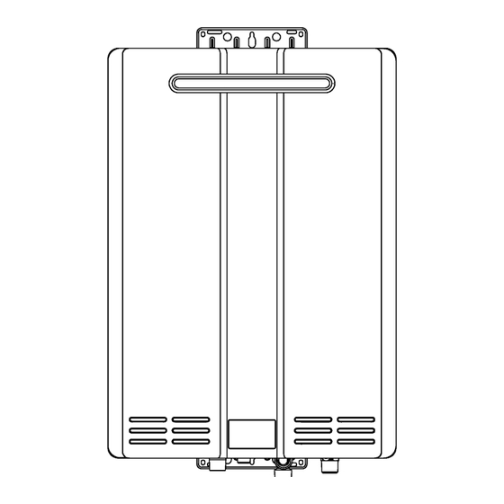
Page 119: Dimensions
Dimensions Pouces (millimètres) RUC80i, RUC90i, RUC98i ø 5.5 (140.2) Tous les modèles RUC98i 5.9 (150) 10.1 (257.7) 1.2 (31.2) SORTIE D’EAU FROIDE SORTIE DE CONDENSATS SORTIE D’EAU CHAUDE RACCORDEMENT DU GAZ SORTIE DE CONDENSATS DIMENSION En pouces (mm) 8.7 (222) 2.8 (70.1) -
Page 120: Courbe De Chute De Pression
Débit d’eau (gallons/minute) Le graphique ci-dessous ne s’applique que pour des arrivées d’eau à 70°F (21 °C) ou moins. Pour des AVIS arrivées d’eau froide à température plus élevée que 70°F (21 °C), contactez Rinnai. Données de flux de sortie RUC98i, RU98e... -
Page 121: Diagramme En Escalier
Diagramme en escalier PHASE NEUTRE POMPE RELAIS 3 FUSIBLE 10 A INTERRUPTEUR CHAUFFAGE DÉTECTEUR DE GEL ANTIGEL RELAIS 2 DÉCHARGEUR DE FOUDRE VARISTANCE VARISTANCE RELAIS 1 ALLUMAGE TERRE ALIENTATION À DÉCOUPAGE CAPTEUR DE ÉLECTROVANNE À FLUX D’EAU MODULATION CIRCUIT DE CAPTEUR CIRCUITDE DE FLUX D’EAU COMMANDE... -
Page 122: Mode Recirculation
Mode recirculation Passez en position ON le le micro-commutateur SW4 dans Le chauffe-eau Rinnai a la capacité de contrôler une pompe de DIPSW 2. recirculation. Deux modes sont disponibles, Economy et Comfort, Pour le mode Economy, passez en position ARRÊT le micro- qui font recirculer l’eau dans le système de plomberie pour... -
Page 123: Séquence De Fonctionnement
être positionnés correctement pour la recirculation température Mode Mode de con- et le mode. Le chauffe-eau Rinnai doit être mis en marche. du Rinnai °F économique fort (Comfort) (Economy) La pompe de recirculation est activée quand le chauffe-eau démarre. - Page 124 RU98e ....REU-KB3237WD-US Points importants concernant votre chauffe-eau Merci d’avoir acheté un chauffe-eau Rinnai sans réservoir. Pour un bon fonctionnement et la sécurité, il est important de suivre ces instructions et de respecter les précautions de sécurité. Lisez attentivement toutes les instructions et la garantie avant de faire fonctionner ce chauffe-eau. Conservez ce manuel en lieu sûr.
-
Page 125: Instructions D'utilisation
Consignes à l’opérateur pour un fonctionnement sûr de son chauffe-eau POUR VOTRE SÉCURITÉ LISEZ CECI AVANT DE COMMENCER AVERTISSEMENT Si vous ne suivez pas exactement ces instructions, il peut en résulter un départ d’incendie ou une explosion entraînant des dégâts matériels et blessures pouvant être fatales. Cet appareil ne comporte pas de veilleuse. -
Page 126: Comment Utiliser Le Contrôleur De Température
Gardez la zone autour de l’appareil dégagée et exempte de traiter votre eau et/ou rincer régulièrement le chauffe-eau. matières combustibles, d’essence et d’autres vapeurs ou Rinnai propose le “Système de conditionnement d’eau liquides inflammables. ScaleCutter” de Southeastern Filtration qui permet une prévention supérieure du niveau d’entartage et du contrôle... -
Page 127: Fixation De La Température
Fixation de la température Le chauffe-eau nécessite un minimum d’écoulement d’eau pour fonctionner. Ce seuil peut être trouvé sur la page de spécifications dans ce manuel. Dans certains cas quand vous n’obtenez pas d’eau chaude ou si l’eau passe de chaude à froide, cela peut venir de ce que l’écoulement d’eau est en-dessous ou trop proche du seuil minimal d’écoulement. -
Page 128: Températures Disponibles Avec Un Contrôleur
Températures disponibles avec un contrôleur Le chauffe-eau peut fournir de l’eau à un seul niveau de température à la fois. Les températures possibles sont données ci-dessous. Une température inférieure à 98°F (37 °C) peut s’obtenir au robinet en mélangeant avec de l’eau froide. Pour changer l’échelle des températures et passer de Celsius à... -
Page 129: Options De Température Sans Contrôleur De Température
Options de température sans contrôleur de température Le réglage de température par défaut de cet appareil installé sans contrôleur de température est de 120°F (49 °C). Si on le souhaite ce réglage de température peut être changé pour 140°F (60 °C) en jouant sur un micro-commutateur. Sur le bloc DIPSW 1, passez le micro-commutateur SW5 sur MARCHE pour avoir 140°F. -
Page 130: Codes De Diagnostic Et Remèdes
Codes de diagnostic et remèdes Certains de contrôles ci-dessous ne doivent être effectués que par un professionnel agréé. Les simples AVERTISSEMENT consommateurs ne doivent jamais tenter une intervention qu’ils ne sont pas qualifiés pour effectuer. Code Définition Remède Interruption du secteur durant un remplissage de baignoire Fermez tous les robinets d’eau chaude. - Page 131 On/Off (M/A) du contrôleur de température. Des codes LC à répétition vont LC2,…) pour “LC”) éventuellement verrouiller le chauffe-eau. Veuillez appeler le service technique chez Rinnai. Un entretien a été effectué Indique d’un professionnel agréé a effectué une intervention ou corrigé un problème. Nettoyez le filtre d’arrivée d’eau.
-
Page 132: Entretien Nécessaire
Entretien nécessaire L’appareil doit être inspecté annuellement par un professionnel agréé. Installation et interventions de service doivent être effectuées par un professionnel agréé. Ce professionnel agréé doit vérifier le bon fonctionnement après une intervention AVERTISSEMENT Pour vous protéger avant d’effectuer une intervention d’entretien : •... -
Page 133: L'hiver
filtre à eau. Rincez le filtre pour éliminer tous les débris. Des électrovannes de vidange soient achetées et Remettez le filtre en place et rouvrez les vannes installées pour vider automatiquement le chauffe-eau d’isolement. en cas de coupure d’alimentation secteur. Elles sont proposées dans un kit, N°... -
Page 134: Rinçage De L'échangeur Thermique
Un code de diagnostic LC0~LC9 ou “00” ou 58 indique que le chauffe-eau commence à s’entartrer et doit être rincé. Ne pas le faire endommagerait son échangeur thermique. Des dommages causés par une accumulation de tartre ne sont pas couverts par la garantie de l’appareil. Rinnai recommande fortement l’installation de vannes d’isolement pour permettre un rinçage de l’échangeur thermique. -
Page 135: Vidange Manuelle Du Chauffe-Eau
Vidange manuelle du chauffe-eau Pour éviter des brûlures, attendez que l’équipement ait refroidi avant de vidanger l’eau. AVERTISSEMENT L’eau restera longtemps chaude dans l’appareil après son arrêt. Si le chauffe-eau ne doit pas être utilisé durant une période où il pourrait geler, il est recommandé que l’eau à l’intérieur soit vidangée. -
Page 136: Réglementations Officielles
Réglementations officielles AVIS AVANT TOUTE INSTALLATION Ce chauffe-eau à ventilation directe sans réservoir doit être installé par un professionnel agréé. Si vous n’avez pas reçu la formation appropriée, vous ne devez pas installer cet appareil. IMPORTANT : Dans l’état américain du Massachusetts (248 CMR 4.00 et 5.00) Pour tout équipement carburant au gaz à... -
Page 137: Pièces De Rechange
Pièces de rechange La fiche technique, qui est située sur la face intérieure du couvercle avant du chauffe-eau, contient une liste Ensemble de commande de gaz Kit d’électrode/ tige de gaz complète illustrée des pièces. N° d’article de la fiche technique Ensemble de commande de gaz Kit d’électrode/ tige de gaz 116, 117... -
Page 138: Garantie
Ce qui est couvert La garantie limitée standard de Rinnai couvre tous les défauts dus aux matériaux ou à la main-d’œuvre quand le produit est installé et exploité en conformité avec les instructions d’installation écrites de Rinnai, en fonction des termes de ce document de garantie limitée. - Page 139 Limitations des garanties Personne n’est autorisé à exprimer toute autre garantie au nom de la Rinnai America Corporation. Sauf ce qui est formulé expressément ici, il n’y a pas d’autres garanties, explicites ou implicites, incluant sans y être limité les garanties de valeur marchande ou d’adéquation pour une finalité...
- Page 140 également disponibles sur le site Web de Rinnai (www.rinnai.us). APPLICATIONS RÉSIDENTIELLES : La durée de garantie limitée pour la couverture de la main-d’œuvre des chauffe-eau sans réservoir modèles RUC80i, , installés dans une application résidentielle, est prolongée sur 48 mois de plus (soit RUC90i, RUC98i, RU80e, RU90e et RU98e un total de couverture de 60 mois pour la main-d’œuvre à...
- Page 141 Manuel de Série KBD...