CDVI SASIC Manuel D'installation
Unité de gestion sas (centrale + pupitre de gestion)

Manuels Connexes pour CDVI SASIC


Sommaire des Matières pour CDVI SASIC
- Page 1 FRANCAIS ENGLISH SASIC SASCP Unité de gestion SAS (Centrale + pupitre de gestion) Interlocking controller + Control panel Gamme: Verrouillage DIAX Range: DIAX Locking Devices ® ® MANUEL D’INSTALLATION INSTALLATION MANUAL Group Products...
-
Page 2: Table Des Matières
5.2 Description des borniers ................8 6] INSTALLATION ....................10 6.1 Eléments du système ................... 10 6.1.1 Centrale SASIC ..................10 a) Positionnement des DipSwitches avant la mise sous-tension .........10 b) Les voyants du SAS..................11 6.2 Système de verrouillage ................12 6.2.1 Alimentation 12 V interne ................. -
Page 3: Presentation Produit
Signalisation lumineuse avec ou sans bouton d’appel. Périphériques possibles. Centrale SASIC Dimensions (L x l x P) : - Coffret = 402 x 325 x 99 mm - Pupitre = 189 x 134 x 53 mm Il existe deux modes de fonctionnement,... -
Page 4: Rappels Et Recommandations
2] RAPPELS ET RECOMMANDATIONS Rappel de câblage C. La liaison du couvercle avec la protection de terre - La distance entre le SASIC et le dernier pupitre doit être réalisée par le conducteur jaune / vert SASCP peut atteindre 100 m maximum. -
Page 5: Élements Fournis
MANUEL D’INSTALLATION SASIC Unité de gestion SAS 3] ÉLEMENTS FOURNIS SASKIT SASKIT2DS SASKIT2DSE SASKITDS2DX SASKITDS2EDX centrale Switch anti- arrachement Switch anti- arrachement boitier Serrure boîtier Câbles batterie Varistance Borniers 2 X 10 points, 3 X 8 points, 4 X 3 points, 1 X 5 points femelle Sémaphores :... -
Page 6: Montage
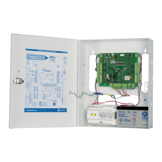
Unité de gestion SAS 4] MONTAGE Après avoir vérifi é que le kit de montage du SASIC soit complet, vous allez pouvoir procéder à l’installation fi nale du produit. Réunissez le matériel approprié (Perceuse, tournevis, mètre,…) et suivez les recommandations de montage de cette centrale. -
Page 7: Schéma De Câblage
MANUEL D’INSTALLATION SASIC Unité de gestion SAS 5] SCHÉMA DE CÂBLAGE 5.1 Schéma de fonctionnement global Centrale SASIC CAA360USBRS Convertisseur RS485/USB Pupitre principal. Pupitre virtuel. De 1 à 4 pupitres peuvent être connectés. De 1 à 4 PC peuvent être connectés. -
Page 8: Description Des Borniers
MANUEL D’INSTALLATION SASIC Unité de gestion SAS 5.2 Description des borniers CARTE SAS CARTE SAS Bornier Correspondance Bornier Correspondance 1 > Bornier 5 point : Sémaphore 1 (porte 1 = extérieure) ENTRÉE TAMPER > Bornier 3 points : Contact fermé au repos / Alarme à l’ouverture Voyant vert (sortie) Tamper + (court-circuiter avec 3 si non utilisé) - Page 9 MANUEL D’INSTALLATION SASIC Unité de gestion SAS Emplacement fusible 2A B7AH Batterie 12V - 7aH ADC123A Alimentation : 230 V AC ± 10% ; 50/60 Hz. SASIC connexion Sémaphore 2 du boîtier SIE/SIS à la Terre 5 6 7 8...
-
Page 10: Positionnement Des Dipswitches Sur La Centrale Sasic Avant La Mise Sous-Tension
MANUEL D’INSTALLATION SASIC Unité de gestion SAS 6] INSTALLATION 6.1 Eléments du système 6.1.1 Centrale SASIC : a) Positionnement des DipSwitches sur la centrale SASIC avant la mise sous-tension Dipswitch 1 Dipswitch 2 Switch Switch Sans batterie 1 pupitre Avec batterie... -
Page 11: B) Les Voyants Du Sas
MANUEL D’INSTALLATION SASIC Unité de gestion SAS Cavaliers Adaptation uniquement sur le pupitre - ST1 = ON permanent le plus éloigné du SAS sur le bus RS485 : - ST2 (Alimentation Porte 1) ST1 (Connexion à la résistance d’adaptation de ligne 120 Ω) •... -
Page 12: Système De Verrouillage
MANUEL D’INSTALLATION SASIC Unité de gestion SAS 6.2 Système de verrouillage 6.2.1 Alimentation 12 V interne a) Electro-serrures (Rupture ou émission) Les serrures préconisées sont les DX4025I/DX4030I/DX4035I en rupture. Gris Vert foncé Rouge Noir Noir Rouge Vert foncé Gris 20 21 22 23 24 25 26... - Page 13 MANUEL D’INSTALLATION SASIC Unité de gestion SAS b) Ventouses Les ventouses préconisées sont V3SR/ V3SRB, V4SR/ V4SRB, V5SR/ V5SRB Vert foncé Rouge Noir Noir Rouge Vert foncé 20 21 22 23 24 25 26 A B M - NO C NC...
-
Page 14: Alimentation 24 V Extérieure
MANUEL D’INSTALLATION SASIC Unité de gestion SAS 6.2.2 Alimentation 24 V extérieure a) Electro-serrures Noir Rouge Vert foncé Rouge Noir Noir Rouge Vert foncé Rouge Noir 20 21 22 23 24 25 26 A B M - NO C NC... -
Page 15: Commande De Verrouillage
SAS ouvert. Commande d’alarme Commande d’ouverture libre des deux (borniers 19 et 20 sur la carte du SASIC) portes (borniers 25 et 26 sur la carte Il s’agit de l’alarme générale déclenchable du SASIC) volontairement par l’utilisateur du SAS en C’est encore une commande prioritaire. -
Page 16: L'urgence Est Prioritaire Sur L'ouverture Libre Et Sur Le Verrouillage
– effet de self. Dans le cas où la gâche, ventouse ou serrure utilisée est du type “Shear Lock”, celle-ci doit être alimentée par une alimentation indépendante du SASIC. 7] GESTION DU SAS 7.1 Gestion du SAS avec pupitre 7.1.1 Présentation du pupitre... -
Page 17: Description Des Signalisations Et Commandes
MANUEL D’INSTALLATION SASIC Unité de gestion SAS Description des signalisations et commandes Voyant alarme Problème sur la centrale SAS, voir scenarii d’alarmes pour identifi er l’origine du problème. générale Voyant & BP Ouvrir Demande d’ouverture simultanée des deux portes pendant 10s. -
Page 18: Les Pupitres Sont Composés De Trois Parties
MANUEL D’INSTALLATION SASIC Unité de gestion SAS Cas n°1 : (DipSwitch_2_SW5 = OFF sur la carte du SAS) Tous les pupitres sont maîtres et ont accès à tous les boutons de commandes. Leurs voyants “M” sont allumés et les “S”... -
Page 19: Fonctionnement 2 : Demander La Main (Esclave)
MANUEL D’INSTALLATION SASIC Unité de gestion SAS Fonctionnement 2 : Demander la main b) En automatique (Esclave) (Mode de fonctionnement commun Un pupitre esclave peut décider de devenir aux 2 portes > DipSwitch_1_SW3 = OFF) maître. En appuyant sur son bouton “M/S”, En mode automatique, lorsqu’il y a un appel... -
Page 20: Pupitre Virtuel Sur Pc
MANUEL D’INSTALLATION SASIC Unité de gestion SAS 7.2 Pupitre virtuel sur PC 7.2.1 Installation - Insérer le cd d’installation et cliquer sur “setup.exe” pour lancer l’installation. - Cliquer sur “Suivant”. - Sélectionner le dossier où sera installé le programme puis cliquer sur “Suivant”. -
Page 21: Choix Langue
MANUEL D’INSTALLATION SASIC Unité de gestion SAS 7.2.2 Confi guration Choix langue : Au premier lancement du logiciel, cliquer sur la langue qui sera utilisée parmi les suivantes : - Français - English - Español - Dutch - Italiano - Deutsh - Svenska Confi... -
Page 22: Déconnexion
MANUEL D’INSTALLATION SASIC Unité de gestion SAS Connexion : C’est l’état de l’écran lorsqu’on est bien connecté à la centrale SAS Temporisation : Après la connexion la centrale SAS renvoie les temporisations des 2 portes qui peuvent être modifi ées à tout moment en cours d’utilisation. -
Page 23: Programmation De La Télécommande Rf
- Après une temporisation, le voyant L2 Les temporisations d’ouverture s’éteint : fi n d’enregistrement. sont celles défi nies sur la centrale SASIC, soit par dipswitch, soit par un PC. 3. Enregistrement du canal 3 (L3) - Appuyer et relâcher le bouton RF Lorsqu’une porte est verrouillée... -
Page 24: Effacer Complètement La Mémoire Du Récepteur Rf
MANUEL D’INSTALLATION SASIC Unité de gestion SAS Effacer complètement la mémoire du récepteur RF - Appuyer sur le bouton RF jusqu’à ce que le voyant L1 s’allume. - Relâcher le bouton RF. - Appuyer à nouveau jusqu’à ce que les voyants L3 et L4 clignotent 3 fois. -
Page 25: Conditions De Garantie À Vie Limitée [Extrait]
à la condition, qu’il soit installé conformément aux préconisations du fabricant et qu’il n’y ait pas eu d’interventions ou de modifi cations sur le produit. La responsabilité de CDVI se limite à la réparation ou à l’échange du produit. CDVI n’assume aucune responsabilité concernant les dommages sur les biens ou les personnes. - Page 52 Reference : G0301FR0349V06 Extranet : EXE-CDVI_IM SASIC-SASCP CMYK A5 EN-FR 06 Creator of electronic access solutions *G0301FR0349V06* CDVI Group FRANCE (Headquarter/Siège social) Phone: +33 (0)1 48 91 01 02 Fax: +33 (0)1 48 91 21 21 CDVI CDVI CDVI CDVI UK...