
Manuels Connexes pour Sportplus SP-MR-010


Sommaire des Matières pour Sportplus SP-MR-010
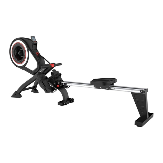
- Page 1 GEBRAUCHSANLEITUNG TURBINEN-RUDERMASCHINE USER MANUAL TURBINE ROWER MODE D'EMPLOI RAMEUR TURBINE SP-MR-010...
-
Page 2: Table Des Matières
Sehr geehrte Kundin, Sehr geehrter Kunde, Wir gratulieren Ihnen zu Ihrem neuen SportPlus Produkt und sind überzeugt, dass Sie mit diesem Produkt zufrieden sein werden. Um eine stets optimale Funktion und Leistungsbereitschaft Ihres Produktes zu gewähr- leisten, beachten Sie Folgendes: Bevor Sie das Produkt das erste Mal benutzen, lesen Sie sich die folgende Bedienungs- anleitung sorgfältig durch! Das Produkt ist mit Sicherheitsvorrichtungen ausgestattet. -
Page 3: Technische Daten
Computerfunktionen: Zeit, Geschwindigkeit, Distanz, Gesamt- zähler Ruderschläge, Umdrehungen/Min., ca. Kalorienverbrauch, Pulsanzeige. • Funkempfang: 5 kHz (www.sportplus.de/konformitaetserklaerung) 2. SICHERHEITSHINWEISE VERWENDUNGSZWECK • Das Produkt ist für die Nutzung im häuslichen Bereich konzipiert und nicht für medi- zinische oder gewerbliche Zwecke geeignet. •... - Page 4 2. SICHERHEITSHINWEISE • Benutzen Sie das Produkt immer auf einem waagerechten, ebenen, rutschfesten und soliden Untergrund. Benutzen Sie es nie in der Nähe von Wasser und halten Sie aus Sicherheitsgründen rund um das Produkt einen ausreichenden Freiraum von mind. 1 Meter ein. •...
-
Page 5: Übungsbereich
2. SICHERHEITSHINWEISE • Entfernen Sie sämtliches Verpackungsmaterial und legen dann die einzelnen Teile auf eine freie Fläche. Dieses verschafft Ihnen einen Überblick und erleichtert das Zu- sammenbauen. Schützen Sie die Aufbaufläche durch eine Unterlage vor Verschmut- zen bzw. Verkratzen. • Überprüfen Sie nun anhand der Teileliste, ob alle Bauteile vorhanden sind. -
Page 6: Vorbereitung
4. VORBEREITUNG Auf dieser Seite finden Sie alle Teile die in den folgen Schritten montiert werden. 14L/R 11 L/R 8 L/R Bezeichnung Anz. Hauptrahmen Standfuß vorne Mittlerer Standfuß Hinterer Standfuß Sitz Schiene 14 L/R Pedale L/R 11 L/R Ablage für Zugstange (L/R) Fußkappe Schrauben zur Pedal-Befestigung Sicherungsstift... - Page 7 4. VORBEREITUNG Auf dieser Seite finden Sie alle Kleinteile (Schrauben, Unterlegscheiben, Muttern und Werkzeuge) abgebildet, welche Sie zur Montage des Gerätes benötigen. Alle diese Teile liegen auf einer Blisterkarte eingeschweißt der Kartonverpackung bei. Bezeichnung Abbildung Anz. Innensechskantschraube M8x16mm Innensechskantschraube M8x20mm Gummipuffer Federscheibe Unterlegscheibe...
-
Page 8: Montageanleitung
5. MONTAGEANLEITUNG 1. Schritt Nehmen Sie den mittleren Standfuß (91) mit den integrierten Transportrollen zur Hand und fixieren Sie diesen mit zwei Schrauben (19) und zwei Unterlegscheiben (43) am Hauptrahmen (1). - Page 9 5. MONTAGEANLEITUNG 1 34 2. Schritt Schieben Sie die Schiene (45) in die U-förmige Aufnahme am Hauptrahmen (1). Befes- tigen Sie die Schiene mit einer Achse (41) und 2 Sätzen Schrauben (34), Federschei- ben (37) und Unterlegscheiben (38). Zum Schluss stecken Sie den Sicherungsstift (35) wieder in das vordere Loch im Hauptrahmen (1).
- Page 10 5. MONTAGEANLEITUNG 3. Schritt Schieben Sie den Sitz (53) auf die Schiene (45). Bringen Sie 2 Gummipuffer (36) an der Schiene (45) an und sichern Sie mit 2 Schrauben (34). Befestigen Sie 2 Fußkappen (55) am hinteren Standfuß (54) bevor Sie den hinteren Standfuß...
- Page 11 5. MONTAGEANLEITUNG Vorsicht Quetschgefahr! Am Gelenk des Produkts wirken große Hebelkräfte. Fassen Sie das Produkt nicht im Bereich des Knickgelenks an. 4. Schritt Drehen Sie den Hauptrahmen und stellen Sie das hintere Stützrohr auf den Boden. Nehmen Sie die vier Blechschrauben (10) aus den Endkappen für das vordere Stabilisa- tor-Rohr (8 L/R) heraus.
- Page 12 5. MONTAGEANLEITUNG Vorsicht Quetschgefahr! Am Gelenk des Produkts wirken große Hebelkräfte. Fassen Sie das Produkt nicht im Bereich des Knickgelenks an. 5. Schritt Drehen Sie den Hauptrahmen und stellen Sie das vordere Stützrohr auf den Boden. Ziehen Sie den Sicherungsstift (35) heraus und klappen Sie den Hauptrahmen auseinan- der.
- Page 13 5. MONTAGEANLEITUNG 6m m 6. Schritt Stecken Sie die zwei Ablagen für die Zugstange (11 L/R) auf die Öffnungen an der Vor- derseite des Hauptrahmens (1). Befestigen Sie dann das linke und rechte Pedal (14 L/R) an die jeweilige Seite des Haupt- rahmens (1) und befestigen Sie diese mit je zwei Innensechskantschrauben (13).
-
Page 14: Vorbereiten / Abstellen
6. VORBEREITEN / ABSTELLEN Computer / Zugstange Der Computer kann (24) auf- oder zugeklappt werden. Die Zugstange (29) kann in die Ablage für die Zugstange (11 L/R) eingehängt werden. Pedale einstellen Stellen Sie die Pedale (14 L/R) auf Ihre Fußgröße ein, indem Sie den Schlaufenumfang anpassen. - Page 15 6. VORBEREITEN / ABSTELLEN Vorsicht Quetschgefahr! Am Gelenk des Produkts wirken große Hebelkräfte. Fassen Sie das Produkt nicht im Bereich des Knickgelenks an. Zusammenklappen Sie können den Sicherungsstift (35) herausziehen und die Schiene (45) hochklappen, wenn Sie das Gerät nicht benutzen. Sichern Sie das zusammengeklappte Gerät: Stecken Sie den Sicherungsstift wieder in das ursprüngliche Loch.
-
Page 16: Bedienung Des Computers
7. BEDIENUNG DES COMPUTERS Tastenfunktionen: MODE/RESET: • Drücken Sie die Taste MODE/RESET, um zwischen den verschie- denen Funktionen auswählen zu können: Time (Zeit), Count (An- zahl Ruderschläge), Distance (Strecke), Calories (ca. Kalorienver- brauch) und Pulse (Herzfrequenz). Die ausgewählte Funktion blinkt nun. - Page 17 7. BEDIENUNG DES COMPUTERS Funktionen: SCAN (Scannen): Drücken Sie die Taste MODE/RESET bis SCAN auf der Display- anzeige erscheint. Die Anzeige zeigt für jeweils 5 Sekunden Time (Zeit), Count (An- zahl Ruderschläge), Distance (Strecke), Calories (ca. Kalorienverbrauch) und Pulse (Herzfrequenz) an. TIME (Zeit): Die Zeit zeigt Ihnen Ihre verstrichene Trainingszeit bis zu 99:59 Minuten Count (Anzahl Ruderschläge): Zeigt die Anzahl der Ruderschläge der aktuellen Training seinheit an.
-
Page 18: Trainingstipps
8. TRAININGSTIPPS WICHTIGE HINWEISE ZUM TRAINING • Bevor Sie mit dem Training beginnen, konsultieren Sie Ihren Arzt. Fragen Sie ihn, in welchem Umfang ein Training für Sie angemessen ist. Falsches oder übermäßiges Training kann zu Gesundheitsschäden führen. • Vermeiden Sie eine Überbelastung Ihres Körpers. Trainieren Sie nicht, wenn Sie müde oder erschöpft sind. -
Page 19: Wartung & Reinigung
9. ÜBUNG Position • Setzen Sie sich auf den Sitz und platzieren Sie Ihre Füße vorsichtig in den Pedalen. • Nehmen Sie die Zugstange von der Ablage. • In der Anfangsposition sollten die Arme gestreckt, der Oberkörper leicht nach vorne geneigt und Beine angewinkelt sein. - Page 20 12. FEHLERSUCHE FEHLER URSACHE WAS TUN? Computer Keine Anzei- keine Stromversorgung Batterien fehlen – einlegen ge oder keine Batterien leer – neue einlegen Funktion Batterien falsch eingelegt – richtig einlegen keine Kabelverbindung Kabelverbindung überprüfen Wenn dies nicht hilft, Service anrufen Mechanik Fehlende Teile –...
-
Page 21: Reklamationen & Gewährleistungen
Servicezeit: Montag bis Freitag von 9.00 bis 18.00 Uhr Servicehotline: +49 (0)40 - 780 896 – 35* E-Mail: Service@SportPlus.org URL: http://www.SportPlus.org *Nationales Festnetz, Gesprächsgebühren sind von Ihrem Telefonanbieter / Ihrem Te- lefonvertrag abhängig. Bitte achten Sie darauf, dass Sie hierzu folgende Informationen zur Hand haben. - Page 22 14. GEWÄHRLEISTUNGSBESTIMMUNGEN SportPlus versichert, dass das Produkt, auf das sich die Gewährleistung bezieht, aus qualitativ hochwertigen Materialien hergestellt und mit äußerster Sorgfalt überprüft wurde. Voraussetzung für die Gewährleistung ist die Bedienung und der ordentliche Aufbau ge- mäß Bedienungsanleitung. Durch unsachgemäße Nutzung und / oder unsachgemäßen Transport kann die Gewährleistung entfallen.
- Page 23 15. EXPLOSIONSZEICHNUNG...
- Page 24 15. EXPLOSIONSZEICHNUNG...
- Page 25 16. TEILELISTE Beschreibung und Daten Anzahl Hauptrahmen Nylonmutter Laufrolle Innensechskantschraube Quadratische Endkappe Rutschfestes Pad Blechschraube 8 L/R Endkappe für vorderes Stabilisator-Rohr (L/R) Vorderes Stützrohr Blechschraube 11 L/R Ablage für Zugstange (L/R) U-förmige Pedalplatte Innensechskantschraube für Pedal 14 L/R Pedal ( L/R ) Vorderfußstütze Kreuzschlitzschraube Nylonmutter...
- Page 26 Beschreibung und Daten Anzahl Unterlegscheibe Ø8xØ25mm Lagerbuchse 40 L/R Endkappe für Schiene ( L/R ) Achse für Führungsschiene Innensechskantschraube M8x40mm Unterlegscheibe Ø8xØ17mm Vierkantscheibe Schiene 46 L/R Führungsschiene (L/R) Blechschraube Achse für Laufrolle Laufrolle Kreuzschlitzschraube Innensechskantschraube Befestigungsplatte für Sitzschale Sitz Hinteres Stützrohr Fußkappe Fußspange 57 L/R Luftkanal (L/R)
- Page 27 Beschreibung und Daten Anzahl Federkupplung Riemenscheibe Nylonmutter Halterung für Riemenscheibe Lager Klemmfeder Riemen Blechschraube Pulvermetall Riemenscheibe Achse für Riemenscheibe Luftöffnung Blechschraube 89 L/R Kettenabdeckung (L/R) Webband Mittelträgerrohr...
-
Page 28: Technical Data
Dear Customer, Congratulations for choosing a SportPlus product. We have every expectation that you will be fully satisfied with your new purchase. To guarantee optimal function of this product, please adhere to the following instructions: • Before using this product for the first time, please read the manual carefully! •... -
Page 29: Safety Instructions
2. SAFETY INSTRUCTIONS INTENDED PURPOSE • This product is intended for household use and is not suitable for medicinal or commercial purposes. • The maximum permissible weight of a person using this product is 150 kg. • When used regularly, the product strengthens and tightens the muscles in your upper, lower and lateral abdominal muscles (abs). -
Page 30: Information On Assembly
2. SAFETY INSTRUCTIONS ADVICE WITH REGARD TO BATTERIES • Remove the batteries if they are empty or if you are no longer using the product. In this way, you will avoid damages that can be caused by leaking. • Do not charge or use any tools to reactivate batteries. Do not dismantle, throw into fire or short-circuit. -
Page 31: Preparation
3. PREPARATION This page lists all the components that require assembly in the following steps. 14L/R 11 L/R 8 L/R Description Frame Front foot Center foot Rear stabilizer Seat Rail 14 L/R Footplate L/R 11 L/R Pull bar stacks (L/R) Foot cap Screws for footplate installation Safety pin... - Page 32 3. PREPARATION This page depicts all the small parts (screws, washers, nuts and tools) that you will require for assembly. All these parts are included in the packaging, shrink-wrapped on a blister card. Description Illustration Hexagon socket screw M8x16 mm Hexagon socket screw M8x20 mm Rubber pads...
-
Page 33: Assembly Instructions
4. ASSEMBLY INSTRUCTIONS Step 1 Hold the center foot (91) with the built-in transport castors and attach it to the frame (1) using two screws (19) and two washers (43). - Page 34 4. ASSEMBLY INSTRUCTIONS 1 34 Step 2 Slide the rail (45) into the U-shaped mount on the frame (1). Secure the rail using one axis (41) and 2 sets of screws (34), spring washers (37) and washers (38). At the end, reinsert the safety pin (35) into the front hole on the frame (1).
- Page 35 4. ASSEMBLY INSTRUCTIONS 3. Step 3 Slide the seat (53) onto the rail (45). Attach 2 rubber pads (36) to the rail (45) and secure with 2 screws (34). Attach 2 foot caps (55) to the rear stabilizer (54) before installing the rear stabilizer to the runner.
- Page 36 4. ASSEMBLY INSTRUCTIONS 4. Step 4 Turn the frame and place the rear support frame on the floor. Remove the four self-tapping screws (10) from the end caps of the front stabilizer tube (8 L/R). Those are preinstalled to the end caps. Attach the end caps to the front support frame (9) using four self-tapping screws (10).
- Page 37 4. ASSEMBLY INSTRUCTIONS 5. Step 5 Turn the frame and place the front support frame on the floor. Remove the safety pin (35) and unfold the frame. Then reinsert the safety pin (35) into the frame to fix latter one. Note: •...
- Page 38 4. ASSEMBLY INSTRUCTIONS 6m m 6. Step 6 Install the two pull bar stacks (11 L/R) on the holes at the front of the frame (1). Then attach the left and right footplates (14 L/R) to the respective side of the frame (1) using two hexagon socket screws (13) each.
- Page 39 4. ASSEMBLY INSTRUCTIONS 7. Step 7 Flip the computer (24) upwards. You can attach the pull bar (29) to the pull bar mount (11 L/R).
- Page 40 4. ASSEMBLY INSTRUCTIONS 8. Step 8 You may remove the safety pin (35) and flip up the rail (45) when not using the product. CAUTION! Make sure all screws and nuts are securely tightened before using the product.
-
Page 41: Using The Computer
5. USING THE COMPUTER Button functions: MODE/RESET: • Press the MODE/RESET button to switch between different functions: Time, count, distance, calories (approx.), and pulse. The selected function flashes. Press and hold the MODE/RESET button for 2 seconds to reset all •... - Page 42 5. USING THE COMPUTER Functions: SCAN: Press the MODE/RESET button until SCAN appears in the display. The display will show time, count, distance, (approx.) calories and pulse for 5 seconds each. TIME: The time display indicates the training time of up to 99:59 minutes. Count (number of strokes): Indicates the number of strokes of the current workout.
-
Page 43: Tips For Your Workout
6. TIPS FOR YOUR WORKOUT IMPORTANT NOTES ON TRAINING • Please consult your physician before beginning training. Ask your physician about the extent of training appropriate for you. Improper or excessive training may result in damage to health. • Do not overstrain your own body. Do not train when you are tired or exhausted. If you are unaccustomed to physical activity, begin slowly. -
Page 44: Cleaning & Maintenance
7. CLEANING & MAINTENANCE • Make sure that all bolts/nuts are correctly tightened after assembly and before use. • Clean the unit regularly with a slightly damp cloth and a mild cleaning agent. Do not use any solvents to clean the unit. •... -
Page 45: Complaints & Warranty
Monday to Friday from 9:00 am to 6:00 pm Service hotline: +49 (0)40 - 780 896 – 34* or +49 (0) 700 - 77 67 87 587** E-Mail: Service@SportPlus.org URL: http://www.SportPlus.org *German national fixed-line network, call charges depend on your phone company/ your phone contract. -
Page 46: Terms Of Warranty
11. TERMS OF WARRANTY SportPlus guarantees that the product this warranty applies to was manufactured using high-quality materials and has been inspected with the utmost attention. The operation and assembly of the product according to the user manual is a precondition of this warranty. -
Page 47: Exploded Diagram
12. EXPLODED DIAGRAM... - Page 48 12. EXPLODED DIAGRAM...
-
Page 49: Part List
13. PART LIST Description and information Anzahl Frame nylon nut Roller (small) Hexagon socket screw Square end cap Anti-skid pad Self-tapping screw 8 L/R End cap for front stabilizer tube (L/R) Front support frame Self-tapping screw 11 L/R Pull bar stacks (L/R) U-shaped pedal plate Footplate hexagon socket screw 14 L/R Footplate (L/R) - Page 50 Description and information Anzahl Washer Ø8 x Ø25 mm Bearing 40 L/R Rail end cap (L/R) Guide rail axis Hexagon socket screw M8x40 mm Washer Ø8 x Ø17 mm Square washer Rail 46 L/R Guide rail (L/R) Self-tapping screw Runner axis Roller (small) Phillips screw Hexagon socket screw...
- Page 51 Description and information Anzahl Spring coupling Belt wheel nylon nut Belt wheel mount Bearing Clamp spring Belt Self-tapping screw Powder metal Belt wheel Belt wheel axis Air opening Self-tapping screw 89 L/R Chain cover (L/R) Woven band Center support frame...
-
Page 52: Données Techniques
Chère cliente, Cher client, Nous vous félicitons pour l'achat de votre nouveau produit SportPlus et sommes convaincus que vous en serez satisfait. • Pour garantir un fonctionnement parfait et un rendement toujours plus optimal de votre produit, nous vous prions de suivre ces instructions. -
Page 53: Consignes De Sécurité
2. CONSIGNES DE SÉCURITÉ USAGE PRÉVU • Le produit est conçu pour une utilisation dans le secteur privé et non pas dans un but médical ni à des fins commerciales. • Le poids maximal admissible sur ce produit est de 150 kg. •... -
Page 54: Instructions Pour Le Montage
2. CONSIGNES DE SÉCURITÉ INDICATIONS POUR LA MANIPULATION DE PILES • Enlevez les piles lorsqu'elles sont usagées ou si vous n'utilisez plus le produit. Ainsi, vous évitez des dommages qui pourraient résulter de fuites. • Les piles ne doivent pas être rechargées ou réactivées par un quelconque moyen, démantelées, jetées dans un feu ou court-circuitées. -
Page 55: Préparation
3. PRÉPARATION Sur cette page, vous trouverez toutes les pièces qui sont à monter dans les étapes suivantes. 14L/R 11 L/R 8 L/R N° Désignation Quant. Cadre principal Pied avant Pied central Pied de support arrière Siège Rail 14 L/R Pédale L/R 11 L/R Reposoir pour barre de traction (L/R) - Page 56 3. PRÉPARATION Sur cette page, vous trouvez toutes les petites pièces illustrées (vis, rondelles plates, écrous et outils) que vous avez besoin pour l'assemblage de l'appareil. Toutes ces pièces sont conditionnées sur une carte blister pelliculée sur l'emballage carton. N° Désignation Illustration Quant.
-
Page 57: Notice De Montage
4. NOTICE DE MONTAGE 1. étape Prenez le pied central (91) avec les roulettes de transport intégrées en main et fixez-le avec deux vis (19), deux rondelles plates (43) au cadre principal (1). - Page 58 4. NOTICE DE MONTAGE 1 34 2. étape Faites glisser le rail (45) dans le passage en forme de U sur le cadre principal (1). Fixez le rail avec un axe (41) et 2 jeux de vis (34), des rondelles ressorts (37) et des rondelles plates (38).
- Page 59 4. NOTICE DE MONTAGE 3. étape Poussez le siège (53) sur le rail (45). Placez les 2 tampons en caoutchouc (36) sur le rail (45) et sécurisez-le avec 2 vis (34). Fixez 2 capuchons pour pied (55) sur le pied arrière (54) avant que vous n'attachiez le pied arrière au rail de roulement.
- Page 60 4. NOTICE DE MONTAGE 4. étape Tournez le cadre principal et placez le support tubulaire arrière au sol. Enlevez les quatre vis en tôle (10) des capuchons du tube du stabilisateur avant (8 L/R). Elles sont prémontées sur les capuchons d'extrémité. Fixez ensuite les capuchons sur le support tubulaire avant (9) avec quatre vis en tôle (10).
- Page 61 4. NOTICE DE MONTAGE 5. étape Tournez le cadre principal et placez le support tubulaire avant au sol. Tirez sur la goupille de sécurité (35) pour l'enlever et dépliez le cadre principal. Réinsérez ensuite la goupille de sécurité (35) dans le cadre principal, pour fixer celui-ci. Remarque •...
- Page 62 4. NOTICE DE MONTAGE 6m m 6. étape Mettez les deux reposoirs pour la barre de traction (11 L/R) sur les ouvertures à l'avant du cadre principal (1). Attachez ensuite la pédale de gauche et de droite (14 L/R) de chaque côté du cadre principal (1) et fixez les pédales avec à...
- Page 63 4. NOTICE DE MONTAGE 7. étape Dépliez l'ordinateur (24) vers le haut. La barre de traction (29) peut être accrochée dans le reposoir pour la barre de traction (11 L/R).
- Page 64 4. NOTICE DE MONTAGE 8. étape Vous pouvez enlever la goupille de sécurité (35) et relever le rail (45) si vous n'utilisez pas l'appareil. ATTENTION ! Avant d'utiliser l'appareil, assurez-vous que toutes les vis et écrous soient bien serrés.
-
Page 65: Utilisation De L'ordinateur
5. UTILISATION DE L'ORDINATEUR Fonctions des touches : MODE/RESET : • Appuyez sur la touche MODE/RESET pour pouvoir basculer entre les différentes fonctions : Time (durée), Count (nombre de coups de rame), Distance (distance), Calories (consommation de calories approximative) et Pulse (fréquence cardiaque). La fonction sélectionnée clignote maintenant. - Page 66 5. UTILISATION DE L'ORDINATEUR Fonctions : 13. SCAN (scanner) : appuyez sur la touche MODE/RESET jusqu'à ce que SCAN apparaisse sur l'écran d'affichage. L'affichage indique pendant 5 secondes les informations suivantes : Time (durée), Count (nombre de coups de rame), Distance (distance), Calories (consommation de calories approximative) et Pulse (fréquence cardiaque).
-
Page 67: Conseils D'entraînement
6. CONSEILS D'ENTRAÎNEMENT IMPORTANTES REMARQUES POUR L’ENTRAÎNEMENT • Consultez votre médecin, avant de commencer tout entraînement. Demandez-lui quel est l'entraînement approprié à votre condition. Un mauvais entraînement ou une activité physique immodérée peut conduire à des dommages corporels. • Évitez de surmener votre corps. Ne vous entraînez pas, lorsque vous êtes épuisé ou fatigué. -
Page 68: Entretien & Nettoyage
7. ENTRETIEN & NETTOYAGE • Contrôlez après l'assemblage et avant toute utilisation de l'appareil que tous les boulons/écrous sont correctement serrés. • Nettoyez régulièrement l’appareil avec un chiffon légèrement humidifié et si besoin avec l’application d'un produit de nettoyage doux. N'utilisez pas de produits solvants pour le nettoyage. -
Page 69: Réclamations Et Garanties
9 h 00 à 18 h 00 Service hotline : +49 (0)40 780 896 – 35* ou +49 (0) 700 77 67 87 587** Adresse Service@SportPlus.org électronique : Site Internet : http://www.SportPlus.org *Réseau national, les frais d’appel dépendent de votre opérateur/votre abonnement téléphonique. -
Page 70: Dispositions De La Garantie
11. DISPOSITIONS DE LA GARANTIE SportPlus assure, que le produit, qui se réfère à la garantie, a été fabriqué avec des matériaux d’excellente qualité et vérifié avec le plus grand soin. Les conditions indispensables pour le recours à la garantie sont une utilisation et un assemblage corrects selon le mode d’emploi. -
Page 71: Vue Éclatée
12. VUE ÉCLATÉE... - Page 72 12. VUE ÉCLATÉE...
-
Page 73: Liste Des Pièces
13. LISTE DES PIÈCES N° Description et données Quantité Cadre principal Écrou en nylon Roulette Vis à 6 pans Capuchon d'extrémité carré Tampon antidérapant Vis en tôle 8 L/R Capuchon pour tube du stabilisateur avant (L/R) Support tubulaire avant Vis en tôle 11 L/R Reposoir pour barre de traction (L/R) Plaque de pédale en forme de U... - Page 74 N° Description et données Quantité Rondelle plate Ø8xØ25mm Douille du roulement 40 L/R Capuchon pour rail (L/R) Axe pour rail de guidage Vis à 6 pans M8x40mm Rondelle plate Ø8xØ17mm Plaque carrée Rail 46 L/R Rail de guidage (L/R) Vis en tôle Axe pour roulette Roulette Vis cruciforme...
- Page 75 N° Description et données Quantité Embrayage à ressort Poulie Écrou en nylon Support pour poulie Roulement Ressort de serrage Courroie Vis en tôle Pièce métallique en poudre Poulie Axe pour poulie Ouverture d'aération Vis en tôle 89 L/R Couvercle de la chaîne (L/R) Ruban tissé...
- Page 76 Bei technischen Fragen, Informationen zu unseren Produkten und für Ersatzteilbestellungen steht Ihnen unser Service-Team wie folgt zur Verfügung: Servicezeit: Montag bis Freitag von 9.00 bis 18.00 Uhr Servicehotline: 040-780896-35 (Nationales Festnetz, Gebühren providerabhängig) E-Mail: service@sportplus.org URL: http://www.sportplus.de Latupo GmbH Waterloohain 9 22769 Hamburg Germany...