Table des Matières
Publicité
Les langues disponibles
Les langues disponibles
Liens rapides
Betriebsanleitung | Operating instructions | Mode d'emploi | Istruzioni per l'uso |
Instrucciones de servicio | Bruksanvisning |
Buskoppler CMS, B-Design
Bus coupler for CMS, B-Design
Coupleur de bus pour CMS, design B
Accoppiatore bus per CMS, design B
Acoplador de bus para CMS, diseño B
Fältbussnod för CMS, B-Design
CANopen
R412005742/05.2014, Replaces: 11.2013, DE/EN/FR/IT/ES/SV
Publicité
Chapitres
Table des Matières

Manuels Connexes pour Aventics CANopen


Sommaire des Matières pour Aventics CANopen
- Page 1 Instrucciones de servicio | Bruksanvisning | Buskoppler CMS, B-Design Bus coupler for CMS, B-Design Coupleur de bus pour CMS, design B Accoppiatore bus per CMS, design B Acoplador de bus para CMS, diseño B Fältbussnod för CMS, B-Design CANopen R412005742/05.2014, Replaces: 11.2013, DE/EN/FR/IT/ES/SV...
-
Page 3: Table Des Matières
AVENTICS | CANopen | R412005742–BDL–001–AD Inhalt Inhalt Zu dieser Dokumentation ..........7 Gültigkeit der Dokumentation..........7 Erforderliche und ergänzende Dokumentationen... 7 Darstellung von Informationen ..........8 1.3.1 Sicherheitshinweise ............... 8 1.3.2 Symbole ..................9 1.3.3 Abkürzungen ................9 Sicherheitshinweise ........... 10 Zu diesem Kapitel..............10... - Page 4 AVENTICS | CANopen | R412005742–BDL–001–AD Inhalt Inbetriebnahme und Bedienung ........ 33 Voreinstellungen vornehmen ..........33 7.1.1 Baudrate einstellen ............... 33 7.1.2 Adresse am Buskoppler einstellen ........34 7.1.3 Diagnosemeldungen einstellen ......... 35 7.1.4 Ventilversorgung zuordnen ..........36 7.1.5 Busabschluss einstellen ............. 43 Bussystem konfigurieren............44...
- Page 5 AVENTICS | CANopen | R412005742–BDL–001–AD Inhalt Anhang ................. 60 13.1 Electronic Data Sheet (EDS)..........60 13.2 Betriebsverhalten..............61 13.2.1 Anlaufverhalten ..............61 13.2.2 CAN Identifier ................62 13.3 Object Dictionary..............65 13.3.1 Allgemeine OD-Objekte ............66 13.3.2 Herstellerspezifische OD-Objekte ........67 13.3.3 Gerätespezifische OD-Objekte: .......... 69 13.4...
- Page 6 AVENTICS | CANopen | R412005742–BDL–001–AD Inhalt...
-
Page 7: Zu Dieser Dokumentation
AVENTICS | CANopen | R412005742–BDL–001–AD Zu dieser Dokumentation Zu dieser Dokumentation Gültigkeit der Dokumentation Diese Dokumentation richtet sich an Monteure/Bediener. Diese Dokumentation enthält wichtige Informationen, um das Produkt sicher und sachgerecht zu montieren, zu bedienen, zu warten, zu demontieren und einfache Störungen selbst zu beseitigen. -
Page 8: Darstellung Von Informationen
AVENTICS | CANopen | R412005742–BDL–001–AD Zu dieser Dokumentation Darstellung von Informationen Damit Sie mit dieser Dokumentation schnell und sicher mit Ihrem Produkt arbeiten können, werden einheitliche Sicherheitshinweise, Symbole, Begriffe und Abkürzungen verwendet. Zum besseren Verständnis sind diese in den folgenden Abschnitten erklärt. -
Page 9: Symbole
AVENTICS | CANopen | R412005742–BDL–001–AD Zu dieser Dokumentation Tabelle 2: Gefahrenklassen nach ANSI Z535.6-2006 Warnzeichen, Signalwort Bedeutung Kennzeichnet eine gefährliche Situation, in der leichte bis VORSICHT mittelschwere Körperverletzungen eintreten können, wenn sie nicht vermieden wird Sachschäden: Das Produkt oder die ACHTUNG Umgebung können beschädigt... -
Page 10: Sicherheitshinweise
AVENTICS | CANopen | R412005742–BDL–001–AD Sicherheitshinweise Sicherheitshinweise Zu diesem Kapitel Das Produkt wurde gemäß den allgemein anerkannten Regeln der Technik hergestellt. Trotzdem besteht die Gefahr von Personen- und Sachschäden, wenn Sie dieses Kapitel und die Sicherheitshinweise in dieser Dokumentation nicht beachten. -
Page 11: Nicht Bestimmungsgemäße Verwendung
Beispielsweise in Ex-Schutz Bereichen oder in sicherheitsbezogenen Teilen einer Steuerung (funktionale Sicherheit). Für Schäden bei nicht bestimmungsgemäßer Verwendung übernimmt die AVENTICS GmbH keine Haftung. Die Risiken bei nicht bestimmungsgemäßer Verwendung liegen allein beim Benutzer. Zur nicht bestimmungsgemäßen Verwendung des Produkts gehört:... -
Page 12: Allgemeine Sicherheitshinweise
Anwendungen ein, wenn diese Verwendung ausdrücklich in der Dokumentation des Produkts spezifiziert und erlaubt ist. Sie dürfen das Produkt erst dann in Betrieb nehmen, wenn festgestellt wurde, dass das Endprodukt (beispielsweise eine Maschine oder Anlage), in das die AVENTICS-Produkte... - Page 13 AVENTICS | CANopen | R412005742–BDL–001–AD Sicherheitshinweise eingebaut sind, den länderspezifischen Bestimmungen, Sicherheitsvorschriften und Normen der Anwendung entspricht. Allgemeine Hinweise Belasten Sie das Gerät unter keinen Umständen mechanisch. Stellen Sie keine Gegenstände darauf ab. Stellen Sie sicher, dass die Spannungsversorgung innerhalb der angegebenen Toleranz der Module liegt.
-
Page 14: Einsatzbereiche
Der Buskoppler dient zur elektrischen Ansteuerung der Ventile über das CANopen-Feldbussystem. Input-/Output-Module bieten zudem die Möglichkeit, elektrische Ein- und Ausgangssignale über den Busanschluss des Ventilsystems auszugeben. Der Buskoppler ist ausschließlich für den Betrieb als Slave an einem Bussystem CANopen nach EN 50170 Teil 2 bestimmt. -
Page 15: Lieferumfang
AVENTICS | CANopen | R412005742–BDL–001–AD Lieferumfang Lieferumfang Im Lieferumfang sind enthalten: 1 Ventilsystem gemäß Konfiguration und Bestellung 1 Betriebsanleitung zum Ventilsystem 1 Betriebsanleitung zum Buskoppler Im Lieferumfang eines Buskoppler-Teilesatzes sind enthalten: 1 Buskoppler mit Dichtung und 2 Befestigungsschrauben 1 Betriebsanleitung zum Buskoppler Das VS wird individuell konfiguriert. -
Page 16: Gesamtübersicht Ventilsystem Und Module
AVENTICS | CANopen | R412005742–BDL–001–AD Gerätebeschreibung Gesamtübersicht Ventilsystem und Module Das Ventilsystem setzt sich, je nach Bestellumfang, aus den in Abbildung 1 dargestellten Komponenten zusammen: Abb. 1: Gesamtübersicht: Beispielkonfiguration Buskoppler mit I/O-Modulen und montiertem VS 1 E-Endplatte 5 EP-Endplatte für HF03 LG oder HF04 2 Output-Modul 6 Ventilträger... -
Page 17: Gerätekomponenten
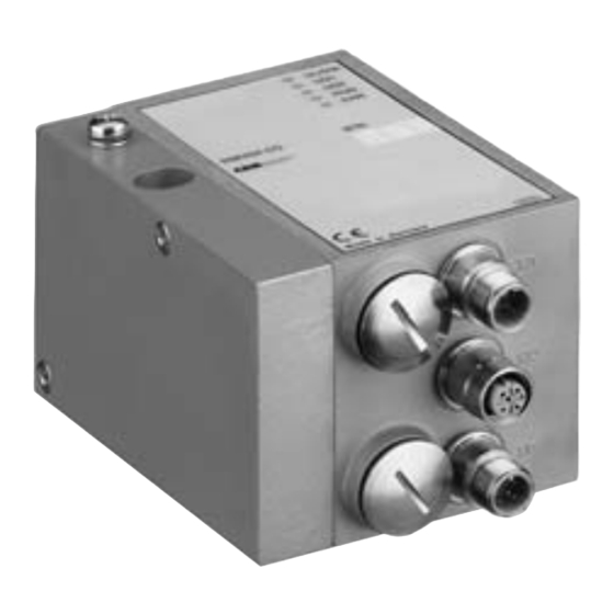
AVENTICS | CANopen | R412005742–BDL–001–AD Gerätebeschreibung Gerätekomponenten 5.2.1 Buskoppler Abb. 2: Übersicht Buskoppler 1 LED-Anzeigen für Diagnosemeldungen 2 BTN-Beschriftungsfeld 3 X71 (BUS IN) Anschluss für den Buskoppler zur Ansteuerung der Ventile und der I/O-Module 4 X72 (BUS OUT) Anschluss zur Ansteuerung der Ventile und... - Page 18 Open System Interconnection – Basic Reference Model Die unteren Schichten des Basic Reference Model basieren auf CAN. CANopen Alle Vorgaben und Richtlinien zu CANopen sind den Spezifikationen des CiA zu entnehmen. Zertifizierung Das Gerät ist nach den Richtlinien des Conformance Test V2.0.2 von CiA zertifiziert.
-
Page 19: Input-/Output-Module
AVENTICS | CANopen | R412005742–BDL–001–AD Gerätebeschreibung 5.2.2 Input-/Output-Module Die Input-/Output-Module bieten über lösbare Steckverbindungen die Möglichkeit, elektrische Eingangssignale über den Busanschluss des Ventilsystems auszugeben. Anzahl anschließbarer An das Ventilsystem mit Buskoppler können sowohl Input- als Module auch Output-Module in beliebiger Kombination angeschlossen werden –... -
Page 20: Input-Module
AVENTICS | CANopen | R412005742–BDL–001–AD Gerätebeschreibung 5.2.3 Input-Module Die Input-Module zum Anschluss von elektrischen Sensor- Signalen sind in zwei Ausführungen erhältlich: 8 x M8 (RMV04-8DI_M8) oder 4 x M12, doppelt belegt (RMV04-8DI_M12) Abb. 3: Input-Modul 8fach: RMV04-8DI_M8 (links) und RMV04-8DI_M12 (rechts) 1 Beschriftungsfeld 2 RMV04-8DI_M8 (links): 8 Eingänge auf 8 x M8-Buchsen... -
Page 21: Output-Module
AVENTICS | CANopen | R412005742–BDL–001–AD Gerätebeschreibung 5.2.4 Output-Module Die Output-Module zum Anschluss der Aktoren sind in zwei Ausführungen erhältlich: 8 x M8 (RMV04-8DO_M8) oder 4 x M12, doppelt belegt (RMV04-8DO_M12) Abb. 4: Output-Modul 8fach: RMV04-8DO_M8 (links) und RMV04-8DO_M12 (rechts) 1 Beschriftungsfeld... -
Page 22: Montage
AVENTICS | CANopen | R412005742–BDL–001–AD Montage Montage Buskoppler am Ventilsystem montieren Sie erhalten Ihr individuell konfiguriertes Ventilsystem komplett verschraubt mit allen Komponenten: Ventilträger Buskoppler gegebenenfalls I/O-Module Die Montage des gesamten Ventilsystems ist in der beiliegenden Betriebsanleitung für das VS ausführlich beschrieben. -
Page 23: Module Beschriften
AVENTICS | CANopen | R412005742–BDL–001–AD Montage Durch jedes Input-/Output-Modul wird das Ventilsystem um 60 mm verlängert (60 x m). Die E-Endplatte hat eine Anbautiefe von 18 mm. Module beschriften Buskoppler Beschriften Sie die für den Buskoppler vorgesehene/ verwendete Adresse am Buskoppler im Feld BTN. -
Page 24: Buskoppler Elektrisch Anschließen
AVENTICS | CANopen | R412005742–BDL–001–AD Montage Buskoppler elektrisch anschließen VORSICHT Anliegende elektrische Spannung Verletzungsgefahr durch elektrischen Schlag. Schalten Sie immer den betreffenden Anlagenteil drucklos und spannungsfrei, bevor Sie am Ventilsystem Module elektrisch anschließen. ACHTUNG Falsche Verkabelung Eine falsche oder fehlerhafte Verkabelung führt zu Fehlfunktionen und zur Beschädigung des Bussystems. -
Page 25: Allgemeine Hinweise Zum Anschluss Des Buskopplers
AVENTICS | CANopen | R412005742–BDL–001–AD Montage 6.3.1 Allgemeine Hinweise zum Anschluss des Buskopplers Benutzen Sie für das Anschließen der Module konfektionierte Steckverbindungen und Kabel. Beachten Sie die in Tabelle 5 dargestellte Pin-Belegung, wenn Sie keine konfektionierten Steckverbindungen und Kabel verwenden. -
Page 26: Buskoppler Als Letzte Station Anschließen
AVENTICS | CANopen | R412005742–BDL–001–AD Montage 6. Drehen Sie die PG-Verschraubung B wieder ein. Achten Sie hierbei auf den korrekten Sitz des Dichtungsrings. 7. Schließen Sie den Schirm an beiden Seiten des Buskabels direkt an das Steckergehäuse (EMV-Gehäuse) an, wenn Sie unkonfektionierte Kabel und Stecker mit Metallgehäuse... -
Page 27: Logik- Und Lastversorgung Des Buskopplers Anschließen
AVENTICS | CANopen | R412005742–BDL–001–AD Montage 6.3.4 Logik- und Lastversorgung des Buskopplers anschließen Über den Gerätestecker X10 (POWER) werden die Ventile und der Buskoppler versorgt. Wenn Sie die Logik- und Lastversorgung des Buskopplers anschließen, müssen Sie die in Tabelle 6 dargestellte Pin- Belegung sicherstellen. - Page 28 AVENTICS | CANopen | R412005742–BDL–001–AD Montage Tabelle 7: Stromaufnahme an X10 (POWER) am Buskoppler Signal Belegung Gesamtstrom Logik und Eingänge max. 1 A Ventile max. 1 A Ventile max. 1 A VORSICHT Unsichere Netzteil-Trennung Die 24-V-Versorgung kann aus einem gemeinsamen Netzteil erfolgen.
-
Page 29: Input-/Output-Module 8Fach Anschließen
AVENTICS | CANopen | R412005742–BDL–001–AD Montage 6.3.5 Input-/Output-Module 8fach anschließen VORSICHT Frei zugängliche stromführende Teile Gefahr von Stromschlag bei Berührung! Halten Sie beim Anschluss der Peripherie (E/A-Schnittstelle) die Anforderungen des Berührungsschutzes gemäß EN 50178, Klassifikation VDE 0160 ein. Input-Modul 1. Verdrahten Sie die Eingänge nach Tabelle 8 (DI8_M8) bzw. - Page 30 AVENTICS | CANopen | R412005742–BDL–001–AD Montage Tabelle 9: Belegung der Eingänge beim Input-Modul 8fach, D18_M12, Buchse M12x1, A-codiert Signal Belegung 24-V-Sensorversorgung + SENSOR+ I1, I3, I5 oder I7 Sensorsignal SENSOR– GND-Bezugspotenzial I0, I2, I4 oder I6 Sensorsignal nicht belegt Gehäuse...
-
Page 31: Lastversorgung Des Output-Moduls Anschließen
AVENTICS | CANopen | R412005742–BDL–001–AD Montage ACHTUNG Zu hoher Summenstrom Jeder Ausgang ist für einen Dauerstrom von max. 0,5 A ausgelegt. Bei Strombelastungen über 0,5 A je Ausgang kann es zu Funktionseinschränkungen kommen. Achten Sie darauf, dass die Strombelastung von 0,5 A je Ausgang nicht überschritten wird. -
Page 32: Fe-Anschluss
EP-Endplatte des VS (1) heraus und in die E-Endplatte (2) ein. Stellen Sie dann dort die Verbindung mit der Funktionserde her. Abb. 7: FE-Anschluss am VS HF04 mit CANopen an EP-Endplatte (1) oder an E-Endplatte (2) Erdung bei... -
Page 33: Inbetriebnahme Und Bedienung
AVENTICS | CANopen | R412005742–BDL–001–AD Inbetriebnahme und Bedienung Inbetriebnahme und Bedienung Voreinstellungen vornehmen Folgende Voreinstellungen müssen Sie durchführen: Baudrate einstellen Adresse am Buskoppler einstellen Diagnosemeldungen einstellen Ventilversorgung zuordnen Busabschluss einstellen Alle diese Einstellungen erfolgen über die Schalter unter den beiden PG-Verschraubungen A und B. -
Page 34: Adresse Am Buskoppler Einstellen
S2 (siehe Abbildung 8) eingestellt. Abb. 8: Adressschalter S1, S2 und Mode-Schalter S3 am Buskoppler Die beiden Drehschalter S1 und S2 für die Stationsadresse des Ventilsystems im CANopen befinden sich unter der PG-Verschraubung A. Vergeben Sie mit S1 und S2 (siehe Abbildung 8) die Stationsadresse von 1 bis 99 frei: –... -
Page 35: Diagnosemeldungen Einstellen
AVENTICS | CANopen | R412005742–BDL–001–AD Inbetriebnahme und Bedienung Die eingegebene Adresse wird beim Hochlaufen (Power-on), nach „NMT Reset Node“ und nach „NMT Reset Communication“ des Buskopplers neu eingelesen. Das Ändern der Adresse im laufenden Betrieb wird daher erst nach einem der aufgeführten Ereignisse wirksam. -
Page 36: Ventilversorgung Zuordnen
AVENTICS | CANopen | R412005742–BDL–001–AD Inbetriebnahme und Bedienung 7.1.4 Ventilversorgung zuordnen Die Schalter S4-S6 für die Zuordnung der Ventilversorgung befinden sich unter der PG-Schraubkappe B (siehe Abbildung 9). Jedem Schalter sind zugeordnet: 4 Anschlussplattenplätze für beidseitig betätigte Ventile (mit Spulen 12 und 14) oder 8 Anschlussplatte für einseitig betätigte Ventile (mit... - Page 37 AVENTICS | CANopen | R412005742–BDL–001–AD Inbetriebnahme und Bedienung ACHTUNG Spannung an Schaltern Schalter können beschädigt werden, wenn bei ihrer Bedienung eine Spannung anliegt. Betätigen Sie die Schalter nur in spannungslosem Zustand! So ordnen Sie die Ventilversorgung zu: 1. Öffnen Sie die untere Schraubkappe B (siehe Abbildung 9 auf Seite 36).
- Page 38 AVENTICS | CANopen | R412005742–BDL–001–AD Inbetriebnahme und Bedienung Von der elektrischen Anschlussseite aus betrachtet müssen zuerst die Anschlussplatten für beidseitig betätigte Ventile und danach die für einseitig betätigte Ventile angeordnet werden. Die maximale Spulenzahl bezogen auf alle Anschlussplatten beträgt 24 (...
- Page 39 AVENTICS | CANopen | R412005742–BDL–001–AD Inbetriebnahme und Bedienung Tabelle 15: Beispiele für die Zuordnung von Schaltern und Ventilversorgung, 24 Ventilspulen Beispiel 1 Beispiel 2 Beispiel 3 Anschlussplatte für beidseitig betätigte Ventile Ventil- Ventil- Ventil- Spule LED Spule LED Spule LED...
- Page 40 AVENTICS | CANopen | R412005742–BDL–001–AD Inbetriebnahme und Bedienung Tabelle 16: Beispiele für die Zuordnung von Schaltern und Ventilversorgung, 24 Ventilspulen Beispiel 4 Beispiel 5 Beispiel 6 Anschlussplatte für Anschlussplatte für ein- und beidseitig betätigte einseitig betätigte Ventile Ventile Ventil- Ventil-...
- Page 41 AVENTICS | CANopen | R412005742–BDL–001–AD Inbetriebnahme und Bedienung Tabelle 17: Beispiele für die Zuordnung von Schaltern und Ventilversorgung, 32 Ventilspulen Beispiel 1 Beispiel 2 Beispiel 3 Anschlussplatte für beidseitig betätigte Ventile Ventilplatz Spule LED Ventilplatz Spule LED Ventilplatz Spule LED A0.0...
- Page 42 AVENTICS | CANopen | R412005742–BDL–001–AD Inbetriebnahme und Bedienung Tabelle 18: Beispiele für die Zuordnung von Schaltern und Ventilversorgung, 32 Ventilspulen Beispiel 4 Beispiel 5 Beispiel 6 Anschlussplatte für Anschlussplatte für ein- und beidseitig betätigte einseitig betätigte Ventile Ventile Ventilplatz Spule LED...
-
Page 43: Busabschluss Einstellen
Inbetriebnahme und Bedienung 7.1.5 Busabschluss einstellen Um Leitungsreflexionen zu minimieren und einen definierten Ruhepegel auf der Übertragungsleitung des CANopen sicherzustellen, muss die Übertragungsleitung an beiden Enden mit einem Busabschluss versehen werden. Beim Buskoppler ist der Busabschluss im Gerät integriert und kann über den Schalter S8 definiert werden. -
Page 44: Bussystem Konfigurieren
AVENTICS | CANopen | R412005742–BDL–001–AD Inbetriebnahme und Bedienung Bussystem konfigurieren Die im Rahmen der Busmasterkonfiguration für das Gesamt- system vorzunehmenden Einstellungen sind den bereits beschriebenen Einstellungen am Buskoppler übergeordnet. Alle Leistungsmerkmale und Objekte für die Konfiguration des Buskopplers sind im Electronic Data Sheet (EDS) enthalten. -
Page 45: Betriebsverhalten
Beachten Sie dabei die Dokumentation des Betreibers zur Konfiguration des Busmasters. Betriebsverhalten Das Verhalten der Busanschaltung ist von den CANopen Eigenschaften sowie von der I/O-Konfiguration abhängig. CAN-Telegramme haben eine maximale Datenkapazität von 8 Byte. Nach den Vorgaben des CiA DS-301 (Master/Slave Connection Set) sind pro CAN-Knoten 4 Kanäle zum Senden von... -
Page 46: Test Und Diagnose Am Buskoppler
AVENTICS | CANopen | R412005742–BDL–001–AD Inbetriebnahme und Bedienung Test und Diagnose am Buskoppler 7.5.1 Diagnoseanzeige am Buskoppler ablesen Die LEDs auf der Frontplatte des Buskopplers geben die in der Tabelle 20 aufgeführten Meldungen wieder. Überprüfen Sie vor Inbetriebnahme und während des Betriebs regelmäßig die Buskopplerfunktionen durch... -
Page 47: Sensoren Am Input-Modul Überprüfen
AVENTICS | CANopen | R412005742–BDL–001–AD Inbetriebnahme und Bedienung Tabelle 20: Bedeutung der Diagnose-LEDs am Buskoppler (Forts.) Signal Beschreibung „ “ blinkt rot++ Modul befindet sich im Error Control Event -Zustand. Ein Heartbeat-/Überwachungsereignis ist aufgetreten. Bedingung: Object 1006 supported. „ “... -
Page 48: Aktoren Am Output-Modul Überprüfen
AVENTICS | CANopen | R412005742–BDL–001–AD Inbetriebnahme und Bedienung 7.5.3 Aktoren am Output-Modul überprüfen Überprüfen Sie vor der Inbetriebnahme die Funktionsfähigkeit und Wirkungsweise der Aktoren mit Hilfe der LED-Anzeigen am Output-Modul. Abb. 12: LED-Anzeigen am Output-Modul M8 (links) und M12 (rechts) -
Page 49: Buskoppler In Betrieb Nehmen
AVENTICS | CANopen | R412005742–BDL–001–AD Inbetriebnahme und Bedienung Buskoppler in Betrieb nehmen Bevor Sie das System in Betrieb nehmen, müssen Sie folgende Arbeiten durchgeführt und abgeschlossen haben: Sie haben das Ventilsystem und den Buskoppler montiert (siehe „Buskoppler am Ventilsystem montieren“ auf Seite 22). -
Page 50: Systemhalt
Leuchtdioden RUN und ERR (siehe Tabelle 20 auf Seite 46) durch gemeinsames, rasches Blinken angezeigt. Beim Systemhalt werden die Ausgänge in den sicheren Zustand gebracht (= „0“) und der Busverkehr zum CANopen-Master abgebrochen. Der Systemhalt kann nur durch einen Neustart der Baugruppe (Power-on) verlassen werden. -
Page 51: Systemhalt Verlassen
Demontage und Austausch Sie können je nach Bedarf den Buskoppler austauschen oder weitere/andere Input-/Output-Module anbauen. Die Gewährleistung von AVENTICS gilt nur für die ausgelieferte Konfiguration und Erweiterungen, die bei der Konfiguration berücksichtigt wurden. Nach einem Umbau, der über diese Erweiterungen hinausgeht, erlischt die Gewährleistung. -
Page 52: Buskoppler Austauschen
AVENTICS | CANopen | R412005742–BDL–001–AD Demontage und Austausch Buskoppler austauschen VORSICHT Anliegende elektrische Spannung und hoher Druck Verletzungsgefahr durch elektrischen Schlag und plötzlichen Druckabbau. Schalten Sie das System drucklos und spannungsfrei! Abb. 13: Buskoppler austauschen, Beispiel 1 Innensechskantschrauben 4 Buskoppler... -
Page 53: Input-/Output-Modul(E) Anbauen
AVENTICS | CANopen | R412005742–BDL–001–AD Demontage und Austausch 3. Ziehen Sie den Buskoppler (4) von den Zugankern (5) ab. 4. Schieben Sie den neuen Buskoppler (4) auf die Zuganker (5) auf. 5. Stellen Sie sicher, dass – die Zuganker (5) vollständig eingeschraubt und –... - Page 54 AVENTICS | CANopen | R412005742–BDL–001–AD Demontage und Austausch VORSICHT Offen liegende Ein-/Ausgänge Gefahr von Stromschlag bei Berührung, Kurzschluss und Schädigung des Systems. Verschließen Sie immer nicht benutzte Eingänge bzw. Ausgänge mit M12- und M8-Verschlusskappen (siehe Zubehör), um die Schutzart IP65 einzuhalten.
- Page 55 AVENTICS | CANopen | R412005742–BDL–001–AD Demontage und Austausch Es dürfen insgesamt maximal 6 Module (Input- oder Output-Module) an einem Ventilsystem montiert sein. Beachten Sie die zulässige Strombelastung! Beachten Sie Abbildung 14 auf Seite 54. 1. Lösen Sie die E-Endplatte (2) vom Buskoppler (7) oder vom letzten Input-Modul (5)/Output-Modul (4) des Ventilsystems (2 Innensechskantschrauben DIN 912 –...
-
Page 56: Pflege Und Wartung
AVENTICS | CANopen | R412005742–BDL–001–AD Pflege und Wartung Pflege und Wartung VORSICHT Anliegende elektrische Spannung und hoher Druck Verletzungsgefahr durch elektrischen Schlag und plötzlichen Druckabbau. Schalten Sie das System vor der Durchführung von Pflege- und Wartungsarbeiten druck- und spannungslos. Module pflegen ACHTUNG Beschädigung der Gehäuseoberfläche durch Lösemittel und... -
Page 57: Technische Daten
AVENTICS | CANopen | R412005742–BDL–001–AD Technische Daten 10 Technische Daten 10.1 Kenngrößen Allgemein Schutzart nach IP 65 im montierten Zustand EN 60 529 / IEC 529 Umgebungstemperatur 0 C bis +50 C ohne Betauung Elektromagnetische Verträglichkeit Störfestigkeit EN 61131-2, EN 61000-6-2 Störaussendung... -
Page 58: Input-Module 8Fach, Rmv04-8Di_M8 Und Rmv04-8Di_M12
AVENTICS | CANopen | R412005742–BDL–001–AD Technische Daten 10.3 Input-Module 8fach, RMV04-8DI_M8 und RMV04-8DI_M12 Elektrik Eingänge DIN EN 61131-2 8 digitale Eingänge, Typ 3, Zweidraht-Näherungsschalter mit einem Ruhestrom von max. 2,5 mA anschließbar Summenstrom der 24-V-Sensorversorgung für alle Eingangsmodule auf 0,7 A begrenzt Eingangsverzögerung 0 –... -
Page 59: Ersatzteile Und Zubehör
AVENTICS | CANopen | R412005742–BDL–001–AD Ersatzteile und Zubehör 11 Ersatzteile und Zubehör 11.1 Buskoppler Bestellnummer VS-Buskoppler für CANopen mit Ansteuerung für 24 Ventilspulen R412005747 VS-Buskoppler für CANopen mit Ansteuerung für 32 Ventilspulen R412008080 Zubehör Dateneingangsstecker, M12x1, 5-polig gerade, A-codiert, Leitungs-Ø 6 – 8 mm 8942051602 Datenausgangsstecker, M12x1, 5-polig gerade, A-codiert, Leitungs-Ø... -
Page 60: Power-Stecker Für Buskoppler Und Output-Modul
13.1 Electronic Data Sheet (EDS) Das Electronic Data Sheet EDS ist eine von CiA spezifizierte ASCII-Datei, in der die Objekte/Leistungsmerkmale eines CANopen-Geräts beschrieben sind. Für den Buskoppler gibt es diese Datei mit dem Dateinamen RXyyRMV4_CO.EDS (yy = Version). Diese Datei kann unter... -
Page 61: Betriebsverhalten
AVENTICS | CANopen | R412005742–BDL–001–AD Anhang 13.2 Betriebsverhalten Das Verhalten der Busanschaltung ist von den CANopen Eigenschaften sowie von der I/O-Konfiguration abhängig. CAN-Telegramme haben eine maximale Datenkapazität von 8 Byte. Nach den Vorgaben des CiA DS-301 (Master/Slave Connection Set) sind pro CAN-Knoten 4 Kanäle zum Senden von PDOs (Process Data Objects) und 4 Kanäle zum Empfangen von... -
Page 62: Can Identifier
AVENTICS | CANopen | R412005742–BDL–001–AD Anhang 13.2.2 CAN Identifier Standard Per Default werden nach dem Anlauf die Identifier des Identifierbelegung Buskopplers eingestellt, die sich nach den Vorgaben des CiA DS-301 (Master/Slave connection set) richten. Die Default-Belegung der Identifier geht hierbei von einer Master-Slave-Beziehung aus, wobei sich das Ventilsystem komplett als Slave verhält. - Page 63 AVENTICS | CANopen | R412005742–BDL–001–AD Anhang Tabelle 23: Standard-Identifierbelegung nach den Vorgaben des CiA DS-301 Byte in Hex Byte in Bit Bedeutung 0x280 reserviert durch CAL 0x281 0x2FF PDO 2 (Transmit) 0x300 reserviert durch CAL 0x301 0x37F PDO 2 (Receive)
- Page 64 AVENTICS | CANopen | R412005742–BDL–001–AD Anhang Tabelle 25: Node-ID-abhängige Identifier-Definitionen Object Identifier Richtung Emergency 128 + Node-ID Senden NMT Node Guarding 1792 + Node-ID Senden/Empfangen 1408 + Node-ID Senden 1536 + Node-ID Empfangen PDO 1 384 + Node-ID Senden PDO 2...
-
Page 65: Object Dictionary
AVENTICS | CANopen | R412005742–BDL–001–AD Anhang 13.3 Object Dictionary Über das Object Dictionary (OD) wird u. a. festgelegt, welche real existierenden Objekte der Kommunikation auf welche Art und Weise zur Verfügung gestellt werden. Das OD ist in Tabellenform organisiert. Die Einträge werden mit einem 16-Bit-Index (Reihenadresse der Tabelle) und einem 8- Bit-Subindex (Spaltenadresse der Tabelle) adressiert. -
Page 66: Allgemeine Od-Objekte
AVENTICS | CANopen | R412005742–BDL–001–AD Anhang Geräteprofile Erwähnt werden hier nur die CiA-Normen: DS-301 CANopen-Kommunikationsprofil DSP-306 Electronic Data Sheet DS-401Geräteprofil für digitale und analoge I/O-Module Geräteklassen Die Geräteprofile beschreiben die besonderen Fähigkeiten bzw. Parameter einer Klasse von Geräten. Bislang wurden folgende Geräteprofile definiert: Digitale bzw. -
Page 67: Herstellerspezifische Od-Objekte
AVENTICS | CANopen | R412005742–BDL–001–AD Anhang im OD gehen bei Spannungsverlust verloren. Nach dem Wiedereinschalten sind alle Objekte auf Default-Wert gesetzt. Detaillierte Informationen zum Aufbau des OD enthalten die entsprechenden Electronic Data Sheets (RXxxRMV4_CO.EDS). Die Dateien liegen im ASCII-Format vor und beschreiben alle Objekte des CANopen-Buskopplers. - Page 68 AVENTICS | CANopen | R412005742–BDL–001–AD Anhang Tabelle 29: Herstellerspezifische OD-Objekte Index Subindex Objektbeschreibung in Hex in Hex 1002 Manufacturer Status Register (MSR) Liegt nicht in dem für Hersteller reservierten Bereich des OD. Die Codierung dieses Objektes obliegt jedoch dem Hersteller.
-
Page 69: Gerätespezifische Od-Objekte
AVENTICS | CANopen | R412005742–BDL–001–AD Anhang 13.3.3 Gerätespezifische OD-Objekte: Die folgenden Objekte sind direkt aus dem Profil des CiA DS- 401, Version 2.0, übernommen. Digital Input-Module Object 6000h: Read Input 8 Bit Dieses Objekt liest den Zustand der Eingangsleitungen in Gruppen von je 8 als 8-Bit-Information. - Page 70 AVENTICS | CANopen | R412005742–BDL–001–AD Anhang Digital Input-Module Object 6100h: Read Input 16 Bit Dieses Objekt liest den Zustand der Eingangsleitungen in Gruppen von je 16 Leitungen als 16-Bit-Information. Maximal lassen sich 254 Gruppen adressieren, also 254 x 16 = 4064 Eingänge.
- Page 71 AVENTICS | CANopen | R412005742–BDL–001–AD Anhang Digital Output-Module Object 6200h: Write Output 8 Bit Dieses Objekt setzt den Zustand der Ausgangsleitungen in Gruppen von je 8 Leitungen als 8-Bit-Information (1 Byte). Maximal lassen sich 254 Gruppen adressieren, also 254 x 8 = 2032 Ausgänge.
- Page 72 AVENTICS | CANopen | R412005742–BDL–001–AD Anhang Digital Output-Module Object 6300h: Write Output 16 Bit Dieses Objekt setzt den Zustand der Ausgangsleitungen in Gruppen von je 16 Leitungen als 16-Bit-Information (2 Byte). Maximal lassen sich 255 Gruppen adressieren, also 255 x 16 = 4080 Ausgänge.
-
Page 73: Diagnose Canopen
AVENTICS | CANopen | R412005742–BDL–001–AD Anhang 13.4 Diagnose CANopen Der Buskoppler unterstützt die Diagnose. Sie kann über das Parameterbyte 2040 zu- bzw. abgeschaltet werden. Default: Diagnose deaktiv Auch bei ausgeschalteter Diagnosemeldung an den Master werden anstehende Diagnosen auf den LEDs angezeigt. -
Page 74: Emcy Error Codes
13.5 EMCY Error Codes Bei Power-on sowie beim Auftreten eines Fehlers sendet der Slave ein Emergency-Telegramm (EMCY). Der Aufbau des EMCY-Telegramms entspricht den Vorgaben des CANopen- Kommunikationsprofils nach CiA DS-301. Die Codierung der einzelnen Fehlerzustände ist folgender Tabelle zu entnehmen:... - Page 75 AVENTICS | CANopen | R412005742–BDL–001–AD Anhang Tabelle 40: Codierung der Fehlerzustände im EMCY-Telegramm Byte EMCY Error Code ErrorReg Manufacturer specific Error Field 1001h Error Reset 0x00 0x00 0x00 0x00 0x00 0x00 0x00 0x00 received invalid PDO 0x10 0x82 ErrorReg 0x00...
-
Page 76: Funktionsumfang
AVENTICS | CANopen | R412005742–BDL–001–AD Anhang 13.6 Funktionsumfang Tabelle 41: Leistung und Funktionsumfang Leistung/Funktion Merkmale Bemerkungen protokollunabhängig Baudrate in kBaud 10, 20, 50, 125, 250, CANopen 500, 1000 max. Eingangsdaten 3 Byte max. Ausgangsdaten 6 Byte Diagnose 1 Byte Istkonfigurations-Information... -
Page 77: Herstellerspezifische Objekte
AVENTICS | CANopen | R412005742–BDL–001–AD Anhang 13.7 Herstellerspezifische Objekte 13.7.1 Manufacturer Status Register (MSR) Das MSR befindet sich bei Index 1002 Subindex 0 im OD. Von den 4 Byte Statusinformationen wird derzeit nur das 1. Byte genutzt. Hier sind der Modul-Status und 1 Bit für eine Fehlersammelmeldung codiert. -
Page 78: Module Control Register (Mcr)
AVENTICS | CANopen | R412005742–BDL–001–AD Anhang 13.7.2 Module Control Register (MCR) Index 2000 Subindex 0 des OD beinhaltet das 16 Bit breite Module Control Register (MCR). Über dieses kann das Verhalten des Buskopplers im Betriebs- und im Fehlerfall verändert werden. Die folgende Tabelle gibt eine Übersicht über die Bedeutung der einzelnen Bits. -
Page 79: Diagnostic Information
AVENTICS | CANopen | R412005742–BDL–001–AD Anhang Tabelle 44: Verhalten des Buskopplers im Fehlerfall EMCY- Fehlerfall Bemerkung Modulstatus Ausgänge Reaktion BUS OFF CAN-Controller befindet sich im „bus off“- gemäß MCR gemäß MCR gemäß MCR Zustand, d. h. der „transmit error counter“... - Page 80 AVENTICS | CANopen | R412005742–BDL–001–AD Anhang Diagnostic Status Index 2020 Subindex 1 enthält den Diagnose-Status. 00hex, keine Diagnose aktiv 01hex, Diagnose steht an Diagnostic Data Index 2020 Subindex 2 ermöglicht das Auslesen der Diagnose- Bytes des Buskopplers. Diese sind in einem Byte wie in Tabelle 46 codiert.
-
Page 81: Parameter Information
AVENTICS | CANopen | R412005742–BDL–001–AD Anhang Configuration Data Index 2030 Subindex 1 enthält die Hardware-Kennung. 0x00 Leeres Element 0x02 8 DI 0x08 8 DO 0x2A Buskoppler: 3 Byte Ausgänge für Ventile 13.7.4 Parameter Information Über den Index 2040 des OD wird der Buskoppler konfiguriert. - Page 82 AVENTICS | CANopen | R412005742–BDL–001–AD Anhang...
-
Page 83: Stichwortverzeichnis
AVENTICS | CANopen | R412005742–BDL–001–AD Stichwortverzeichnis 14 Stichwortverzeichnis Information 79 Abkürzungen 9 einstellen 35 Abmessungen, VS mit Input-/Output-Modul 46 Buskoppler 22 Austausch, Buskoppler 52 Electronic Data Sheet (EDS) 60 Baudrate einstellen 35 Elektrischer Anschluss Beschriftung, Module 23 Buskoppler als letzte... - Page 84 AVENTICS | CANopen | R412005742–BDL–001–AD Stichwortverzeichnis Inbetriebnahme 49 OD-Objekte Input-/Output-Module gerätespezifisch 69 anbauen 53 hersteller- Beschriftung 23 spezifisch 67, 77 Ersatzteile, Zubehör 59 Output-Modul Test und Diagnose 46 Beschreibung 21 Input-Modul Lastversorgung Beschreibung 20 anschließen 31 Test und Diagnose 47...
- Page 85 AVENTICS | CANopen | R412005742–BDL–001–AD Contents Contents About this document ........... 89 Documentation validity ............89 Required and supplementary documentation....89 Presentation of information ..........89 1.3.1 Safety instructions ..............90 1.3.2 Symbols ................... 91 1.3.3 Abbreviations used ............... 91 For your safety ............91 About this chapter..............91...
- Page 86 AVENTICS | CANopen | R412005742–BDL–001–AD Contents 6.3.7 FE connection ..............112 Commissioning and operation ......... 113 Making presettings .............. 113 7.1.1 Setting the baud rate ............113 7.1.2 Setting the bus coupler address ........114 7.1.3 Setting diagnostic messages .......... 115 7.1.4...
- Page 87 13.3.1 General OD objects ............145 13.3.2 Device-specific OD objects ..........146 13.3.3 Device-specific OD objects ..........147 13.4 CANopen diagnosis .............. 151 13.4.1 CANopen operating mode ..........151 13.5 EMCY error codes..............153 13.6 Scope of function..............154 13.7 Manufacturer-specific objects..........
- Page 88 AVENTICS | CANopen | R412005742–BDL–001–AD Contents...
-
Page 89: About This Document
AVENTICS | CANopen | R412005742–BDL–001–AD About this document About this document Documentation validity This documentation contains important information on the safe and appropriate assembly, operation, and maintenance of the bus coupler and how to remedy simple malfunctions yourself. Read this documentation completely, especially chapter “For your safety”... -
Page 90: Safety Instructions
AVENTICS | CANopen | R412005742–BDL–001–AD About this document 1.3.1 Safety instructions This documentation contains safety instructions before any steps that involve a risk of personal injury or damage to property. The measures described to avoid these hazards must be observed. -
Page 91: Symbols
AVENTICS | CANopen | R412005742–BDL–001–AD For your safety 1.3.2 Symbols The following symbols indicate information that is not relevant for safety but that assists in comprehending the documentation. Table 3: Meaning of the symbols Symbol Meaning If this information is disregarded, the product cannot be used or operated optimally. -
Page 92: Intended Use
For example, in areas with explosion protection or in safety-related components of control systems (functional safety). AVENTICS GmbH is not liable for any damages resulting from improper use. The user alone bears the risks of improper use of the product. -
Page 93: Personnel Qualifications
Observe the safety instructions and regulations of the country in which the product is used or operated. Only use AVENTICS products that are in perfect working order. Follow all the instructions on the product. Persons who assemble, operate, disassemble, or maintain AVENTICS products must not consume any alcohol, drugs, or pharmaceuticals that may affect their ability to respond. -
Page 94: Safety Instructions Related To The Product And Technology
You may only commission the product if you have determined that the end product (such as a machine or system) in which the AVENTICS products are installed meets the country-specific provisions, safety regulations, and standards for the specific application. -
Page 95: Applications
Only use water to do this and, if necessary, a mild detergent. Applications The bus coupler is used to control valves via the CANopen field bus system. Input/output modules allow electrical input and output signals to be output via the valve system's bus connection. -
Page 96: Delivery Contents
1 bus coupler with seal and 2 mounting screws 1 operating instructions for the bus coupler The valve system is individually configured. You can find the exact configuration in the AVENTICS Internet configurator under your order number. Device description The bus coupler makes it possible to control the VS via a field bus system. -
Page 97: Overview Of The Valve System And Modules
AVENTICS | CANopen | R412005742–BDL–001–AD Device description Overview of the valve system and modules The valve system consists of the following parts as illustrated in Fig. 1 (depending on the order): Fig. 1: Overview: Bus coupler sample configuration with I/O modules and mounted VS HF03 LG or HF04... -
Page 98: Device Components
3 X71 (BUS IN) connection for the bus coupler to control valves and the I/O modules 4 X72 (BUS OUT) connection for the CANopen to control valves and the I/O modules 5 X10 (POWER) connection to supply voltage to the valve... - Page 99 System Interconnection – Basic Reference Model The lower levels of the Basic Reference Model are based on CAN. CANopen All CANopen standards and guidelines can be found in the CiA specifications. Certification The device is certified according to the specifications of the CiA Conformance Test V2.0.2.
-
Page 100: Input/Output Modules
AVENTICS | CANopen | R412005742–BDL–001–AD Device description 5.2.2 Input/output modules The input/output modules with releasable plug connections allow electrical input signals to be output via the valve system's bus connection. Number of Input as well as output modules can be connected to the valve... -
Page 101: Output Modules
AVENTICS | CANopen | R412005742–BDL–001–AD Device description 5.2.4 Output modules The output modules used to connect the actuators are available in two versions: 8x M8 (RMV04-8DO_M8) or 4x M12, double-assigned (RMV04-8DO_M12) Fig. 4: 8x output module RMV04-8DO_M8 (left) and RMV04-8DO_M12 (right) -
Page 102: Assembly
AVENTICS | CANopen | R412005742–BDL–001–AD Assembly Assembly Assembling the bus coupler on the valve system You will receive your individually configured valve system HF03 LG or HF04 series completely fitted with all components: Valve terminal Bus coupler I/O modules (if needed) The operating instructions accompanying the VS describe in full how to assemble the entire valve system. -
Page 103: Labeling The Module
AVENTICS | CANopen | R412005742–BDL–001–AD Assembly Each input/output module extends the valve system by 60 mm (60 x m). The E end plate has an installation depth of 18 mm. Labeling the module Bus coupler The address provided/used for the bus coupler is inscribed on the bus coupler in the bus participant's (BTN) field. -
Page 104: Connecting The Bus Coupler Electrically
AVENTICS | CANopen | R412005742–BDL–001–AD Assembly Connecting the bus coupler electrically CAUTION Applied electric voltage Danger of injury from electric shock Make sure the relevant system component is not under pressure or voltage before electrically connecting modules to the valve system. -
Page 105: General Notes On Connecting The Bus Coupler
AVENTICS | CANopen | R412005742–BDL–001–AD Assembly 6.3.1 General notes on connecting the bus coupler Benutzen Sie für das Anschließen der Module konfektionierte Steckverbindungen und Kabel. Observe the pin assignment in 1 if you do not use pre- assembled plug connections and cables. -
Page 106: Connecting The Bus Coupler As A Final Station
AVENTICS | CANopen | R412005742–BDL–001–AD Assembly 6. Screw the PG fitting B back in. Pay attention that the sealing ring is positioned correctly. 7. Connect the shield on both sides of the bus cable directly to the plug housing (EMC housing) if non-pre-assembled cables and plugs with metal housing are used. -
Page 107: Connecting The Bus Coupler's Logic And Load Supply
AVENTICS | CANopen | R412005742–BDL–001–AD Assembly 6.3.4 Connecting the bus coupler's logic and load supply Power is supplied to the valves and the bus coupler via the X10 plug (POWER). When connecting the logic and load supply of the bus coupler, ensure pin assignment according to Tab. - Page 108 AVENTICS | CANopen | R412005742–BDL–001–AD Assembly Table 7: Power consumption on X10 (POWER) on bus coupler Signal Assignment Total current Logic supply and input max. 1 A Valves max. 1 A Valves max. 1 A CAUTION Unsafe power pack isolation A standard power pack can supply all system components with 24 V.
-
Page 109: Connect The 8X Input/Output Modules
AVENTICS | CANopen | R412005742–BDL–001–AD Assembly 6.3.5 Connect the 8x input/output modules CAUTION Freely accessible conductive parts Risk of electric shock on contact! When connecting peripheral devices (I/O interface), observe the requirements to protect against accidental contact in accordance with EN 50178, classification VDE 0160. - Page 110 AVENTICS | CANopen | R412005742–BDL–001–AD Assembly Output-Modul 1. Wire the outputs according to Tab. 10 (DO8_M8) or Tab. 11 (DO8_M12). 2. Connect the electrical inputs/outputs to the I/O modules with M8 or M12 coupling plugs (accessories). 3. To ensure the IP65 protection class, close unused sockets with M8 or M12 protective caps (accessories).
-
Page 111: Connecting The Output Module Load Supply
AVENTICS | CANopen | R412005742–BDL–001–AD Assembly 6.3.6 Connecting the output module load supply Each output module has its own M12 connection for the load supply. Each of the 4 outputs are supplied via the load supply. The U and U voltages are galvanically isolated. -
Page 112: Fe Connection
(2). Then establish the connection with functional grounding there. Fig. 7: FE connection on the VS HF04 with CANopen on the EP end plate (1) or an E end plate (2) VS HF03 LG grounding Affix the grounding on the FE connection of the E end plate... -
Page 113: Commissioning And Operation
AVENTICS | CANopen | R412005742–BDL–001–AD Commissioning and operation Commissioning and operation Making presettings The following presettings need to be made: Setting the baud rate Setting the bus coupler address Setting diagnostic messages Assigning the valve supply Setting the bus terminator All of these settings are made using the switch beneath the PG fittings A and B. -
Page 114: Setting The Bus Coupler Address
S1, S2 address switches and S3 mode switch on the bus coupler Both S1 and S2 rotary switches for the valve system station address in CANopen are located beneath the PG fitting A. Assign the station address freely from 1 to 99 using S1 and S2 (see 8). -
Page 115: Setting Diagnostic Messages
The S3 mode switch used to set the diagnostic messages is located under the PG fitting A (see Fig. 8 on page 114). The system is CANopen conform on delivery. Diagnosis is deactivated (S3/5 set to OFF). Activate or deactivate the diagnostic message to the master with the switch S3/5. -
Page 116: Commissioning And Operation
AVENTICS | CANopen | R412005742–BDL–001–AD Commissioning and operation 7.1.4 Assigning the valve supply The S4-S6 switches for assigning the valve supply are located beneath the PG screw cap B (see 9). The following is assigned to each switch: 4 subbase positions for bistable valves (with solenoids 12 and 14) or 8 Subbase for mono-stable valves (with solenoid 14). - Page 117 AVENTICS | CANopen | R412005742–BDL–001–AD Commissioning and operation NOTICE Voltage on switches Switches can be damaged if voltage is applied to them during operation. Always operate switches in a voltage-free state! How to assign the valve supply: 1. Open the lower screw cap B (see Fig. 9 on page 116).
- Page 118 AVENTICS | CANopen | R412005742–BDL–001–AD Commissioning and operation Table 15: Examples for assignment of switches and valve supply, 24 valve solenoids Example 1 Example 2 Example 3 Subbase for bistable valves Valve Solenoid Valve Solenoid Valve Solenoid position position position A0.0...
- Page 119 AVENTICS | CANopen | R412005742–BDL–001–AD Commissioning and operation Table 16: Examples for assignment of switches and valve supply, 24 valve solenoids Example 4 Example 5 Example 6 Subbase for mono-stable Subbase for mono-stable and bistable valves valves Valve Solenoid Valve...
- Page 120 AVENTICS | CANopen | R412005742–BDL–001–AD Commissioning and operation Table 17: Examples for assignment of switches and valve supply, 32 valve solenoids Example 1 Example 2 Example 3 Subbase for bistable valves Valve Solenoid Valve Solenoid Valve Solenoid position position position A0.0...
- Page 121 AVENTICS | CANopen | R412005742–BDL–001–AD Commissioning and operation Table 18: Examples for assignment of switches and valve supply, 32 valve solenoids Example 4 Example 5 Example 6 Subbase for mono-stable Subbase for mono-stable and bistable valves valves Valve Solenoid Valve...
-
Page 122: Setting The Bus Terminator
Setting the bus terminator In order to minimize line reflections and to ensure a defined rest level on the CANopen transfer line, a bus terminator has to be fitted on both ends of the transfer line. In the bus coupler, the bus terminator has been integrated into the device and can be defined using switch S8. - Page 123 AVENTICS | CANopen | R412005742–BDL–001–AD Commissioning and operation All the performance data and objects for the configuration of the bus coupler are listed in the Electronic Data Sheet (EDS). This file is on hand for the bus coupler and is called RXyyRMV4_CO.EDS (yy = version).
-
Page 124: Operating Behavior
AVENTICS | CANopen | R412005742–BDL–001–AD Commissioning and operation Operating behavior The behavior of the bus connection depends on the CANopen characteristics as well as the I/O configuration. CAN frames have a maximum data capacity of 8 bytes. When using the standards for CiA DS-301 (Master/Slave Connection Set) 4 channels to send PDOs (Process Data Objects) and 4 channels to receive PDOs can be defined per CAN node. -
Page 125: Testing And Diagnosis On The Bus Coupler
AVENTICS | CANopen | R412005742–BDL–001–AD Commissioning and operation Testing and diagnosis on the bus coupler 7.5.1 Reading the bus coupler diagnostic display The LEDs on the front panel of the bus coupler show the messages from Tab. 20. Before commissioning and during operation, regularly check bus coupler functions by reading the diagnostic displays. -
Page 126: Check Sensors On The Input Module
AVENTICS | CANopen | R412005742–BDL–001–AD Commissioning and operation Table 20: Definitions for diagnostic LEDs on the bus coupler (cont.) Signal Description “ ” Flashes red++ Module is in error control event state. A heartbeat/monitoring event has occurred. Condition: Object 1006 supported. -
Page 127: Check Actuators On The Output Module
AVENTICS | CANopen | R412005742–BDL–001–AD Commissioning and operation 7.5.3 Check actuators on the output module Before commissioning, check the actuator function and the method of operation using the LED displays on the output module. Fig. 12: LED displays on the M8 output module (left) and M12 (right) -
Page 128: Commissioning The Bus Coupler
AVENTICS | CANopen | R412005742–BDL–001–AD Commissioning and operation Commissioning the bus coupler Before commissioning the system, the following steps must have been carried out and completed: You have assembled the valve system and the bus couplers (see "Assembling the bus coupler on the valve system" on page 102). -
Page 129: System Stop
AVENTICS | CANopen | R412005742–BDL–001–AD Commissioning and operation 1. Switch on the operating voltage. 2. Check the LED displays on all modules. 3. Switch on the compressed air supply. System stop The bus coupler's "system stop" mode is indicated when both the RUN and ERR LEDs are flashing fast (see 20 on page 125). -
Page 130: Disassembly/Exchange
Disassembly/Exchange You can either exchange the bus coupler or connect additional input/output modules as needed. The warranty from AVENTICS only applies to the delivered configuration and extensions that have been taken into account in the configuration. The warranty no longer applies after a conversion that exceeds these extensions. - Page 131 AVENTICS | CANopen | R412005742–BDL–001–AD Disassembly/Exchange Fig. 13: Exchanging the bus coupler, example 1 Hexagonal socket-head screws 4 Bus coupler 2 E end plate 5 Tie rod 3 Seal 6 EP end plate VS HF03 LG or HF04 1. Disconnect the electrical connections from the bus coupler (4).
-
Page 132: Mounting Input/Output Module(S)
AVENTICS | CANopen | R412005742–BDL–001–AD Disassembly/Exchange 7. Make all the presettings on the new bus coupler (4) (see "Making presettings" on page 113). 8. Re-establish the electric connections. 9. Check the configuration and adjust it if necessary (see “Configuring the bus system” on page 122). - Page 133 AVENTICS | CANopen | R412005742–BDL–001–AD Disassembly/Exchange Fig. 14: Mounting input/output modules on the VS HF03 LG or the VS HF04, example 1 Hexagonal socket-head screws 5 Input modules 2 E end plate 6 Tie rod 3 Seal 7 Bus coupler...
- Page 134 AVENTICS | CANopen | R412005742–BDL–001–AD Disassembly/Exchange 2. Screw the tie rods (6) for the input (5) or output modules (4) on the existing tie rods (6) (2 per input (5) or output module (4)). – Ensure that the tie rods (6) are flush with the surface! 3.
-
Page 135: Service And Maintenance
AVENTICS | CANopen | R412005742–BDL–001–AD Service and maintenance Service and maintenance CAUTION Applied electric voltage and high pressure Danger of injury from electric shock and sudden pressure drops. Turn off the system’s pressure and voltage before carrying out any service and maintenance work. -
Page 136: Technical Data
AVENTICS | CANopen | R412005742–BDL–001–AD Technical data 10 Technical data 10.1 Characteristics General Degree of protection according IP 65 when assembled to EN 60 529/ IEC 529 Ambient temperature 0 C to +50 C without condensation Electromagnetic compatibility Interference immunity... -
Page 137: 8X Input Modules, Rmv04-8Di_M8 And
AVENTICS | CANopen | R412005742–BDL–001–AD Technical data 10.3 8x input modules, RMV04-8DI_M8 and RMV04-8DI_M12 Electrical Inputs DIN EN 61131-2 8 digital inputs, type 3, two-wire proximity switch with a quiescent current of max. 2.5 mA can be connected Total current of 24 V sensor supply for all input modules limited to 0.7 A. -
Page 138: Spare Parts And Accessories
11 Spare parts and accessories 11.1 Bus coupler Order number VS bus coupler for CANopen with control for 24 valve solenoids VS bus coupler for CANopen with control for 32 valve solenoids Accessories Data input plug, M12x1, 5-pin straight, A-coded, cable Ø 6 – 8 mm 8942051602 Data output plug, M12x1, 5-pin straight, A-coded, cable Ø... -
Page 139: Power Plug For Bus Coupler And Output Module
13.1 Electronic Data Sheet (EDS) The EDS Electronic Data Sheet is an ASCII file specified by CiA that describes the objects and performance data of a CANopen device. This file is on hand for the bus coupler and is called RXyyRMV4_CO.EDS (yy = version). -
Page 140: Start-Up Behavior
AVENTICS | CANopen | R412005742–BDL–001–AD Appendix 13.2 Operating behavior The behavior of the bus connection depends on the CANopen characteristics as well as the I/O configuration. CAN frames have a maximum data capacity of 8 bytes. When using the standards for CiA DS-301 (Master/Slave Connection Set) 4 channels to send PDOs (Process Data Objects) and 4 channels to receive PDOs can be defined per CAN node. -
Page 141: Can Identifier
AVENTICS | CANopen | R412005742–BDL–001–AD Appendix 13.2.2 CAN identifier Standard identifier After start-up, the bus coupler identifiers are set by default, assignment based on the CiA DS-301 specifications (Master/Slave Connection Set). The default identifier assignment assumes a master/slave relationship whereby the valve system behaves completely as a slave. - Page 142 AVENTICS | CANopen | R412005742–BDL–001–AD Appendix Table 23: Standard identifier assignment in accordance with CiA DS-301 Byte in hex Byte in bit Meaning From From NMT services 0x7F Reserved by CAL 0x80 SYNC message 0x81 0xFF Emergency messages 0x100 Time stamp...
- Page 143 AVENTICS | CANopen | R412005742–BDL–001–AD Appendix On the bus coupler, PDO 1 is assigned by default for transmitting and receiving. Table 25: Identifier definition dependant on node ID Object Identifier Direction Emergency 128 + Node-ID Transmit NMT Node Guarding 1792 + Node-ID...
-
Page 144: Object Dictionary
AVENTICS | CANopen | R412005742–BDL–001–AD Appendix 13.3 Object Dictionary The Object Dictionary (OD) is used for, among other things, determining which existing communication objects can be made available and how. The OD is organized in the form of a table. The entries are addressed with a 16 bit index (table row address) and an 8 bit sub-index (table column address). -
Page 145: General Od Objects
AVENTICS | CANopen | R412005742–BDL–001–AD Appendix Other device profiles are under development, for use in medical technology and the navy, for example. Communications profiles All device profiles have the communication profile from CiA DS- 301 in common. With the communication profile, basic device... -
Page 146: Device-Specific Od Objects
AVENTICS | CANopen | R412005742–BDL–001–AD Appendix Table 28: General OD objects Index in Sub-index Object description in hex 1000 Device type: 0x30191: Only digital IO 1008 Device name: RMV04-CO 1009 Hardware version: 1.1 100A Software version: 1.1 1018 Vendor ID: 0x24... -
Page 147: Device-Specific Od Objects
AVENTICS | CANopen | R412005742–BDL–001–AD Appendix Table 29: Manufacturer-specific OD objects (cont.) Index in Sub-index Object description in hex 2030 Configuration information Number of recognized modules Configuration data One recognition byte per module. The configuration list can be read via an Upload Multiplexed Domain Segment Protocol. - Page 148 AVENTICS | CANopen | R412005742–BDL–001–AD Appendix Table 31: Read input 8 bit objects – entry description Entry description Sub-Index Description Number of Input 8 Bit Access Entry Category Mandatory PDO Mapping Value Range 1h to FEh Default Value Sub-Index 1h – 3h...
- Page 149 AVENTICS | CANopen | R412005742–BDL–001–AD Appendix Table 33: Read input 16 bit objects – entry description Entry description Sub-Index Description Number of Input 16 Bit Access Entry Category Mandatory PDO Mapping Value Range 1h to FEh Default Value Sub-Index 1h – 2h...
- Page 150 AVENTICS | CANopen | R412005742–BDL–001–AD Appendix Table 35: Write output 8 bit objects – entry description Entry description Sub-Index Description Number of Input 8 Bit Access Entry Category Mandatory PDO Mapping Value Range 1h to FEh Default Value Sub-Index 1h – 6h...
-
Page 151: Canopen Diagnosis
AVENTICS | CANopen | R412005742–BDL–001–AD Appendix Table 37: Write output 16 bit objects – entry description Entry Description Sub-Index Description Number of Input 16 Bit Access Entry Category Mandatory PDO Mapping Value Range 1h to FEh Default Value Sub-Index 1h – 3h... - Page 152 The presettings for the “Transmission type” parameter are valid for all PDOs of each slave. A PDO-related setting of this parameter must be carried out with the relevant CANopen service via the bus. With the S3 DIP switch, there is a choice of 4 different default...
-
Page 153: Emcy Error Codes
The slave transmits an emergency telegram (EMCY) during power-on and when there is an error. The set-up of the EMCY telegram is consistent with the definitions of the CANopen communication profile according to CiA DS-301. The coding of the individual error states can be taken from the... -
Page 154: Scope Of Function
AVENTICS | CANopen | R412005742–BDL–001–AD Appendix ErrorReg 10: Communication error (overrun, error state) 80: Manufacturer-specific 13.6 Scope of function Table 41: Task and scope of function Task/function Characteristics Comments Protocol-independent Baud rate in kBaud 10, 20, 50, 125, 250, CANopen 500, 1000 Max. -
Page 155: Manufacturer-Specific Objects
AVENTICS | CANopen | R412005742–BDL–001–AD Appendix 13.7 Manufacturer-specific objects 13.7.1 Manufacturer Status Register (MSR) The MSR is located at index 1002 subindex 0 in the OD. Only the first byte is used in the 4 byte status information at the present time. -
Page 156: Module Control Register (Mcr)
AVENTICS | CANopen | R412005742–BDL–001–AD Appendix 13.7.2 Module Control Register (MCR) The Index 2000 Subindex 0 of the OD contains the 16-bit wide Module Control Register (MCR). The behavior of the bus coupler can be changed during operation and in the case of a fault. -
Page 157: Diagnostic Information
AVENTICS | CANopen | R412005742–BDL–001–AD Appendix Table 44: Behavior of the bus coupler in the case of an error Module EMCY Error case Comments Outputs status reaction BUS OFF CAN controller is in the “bus off” state, According to According to According to which means that the “transmit error... - Page 158 AVENTICS | CANopen | R412005742–BDL–001–AD Appendix Table 46: Coding of the diagnosis bytes Byte Meaning Bit 0 No diagnosis Faulty valve supply fuse or digital output (collective bit) Bit 1 No diagnosis Low load supply voltage U Bit 2 No diagnosis...
-
Page 159: Parameter Information
AVENTICS | CANopen | R412005742–BDL–001–AD Appendix 13.7.4 Parameter information The bus coupler is configured via index 2040 of the OD. Parameter data length Index 2040 Subindex 0 supplies the number of parameterization data: number = 1 Parameter data Index 2040 Subindex 1 und 2 have the same functions. The parameterization data can be written in and the diagnosis can therefore be switched on or off. - Page 160 AVENTICS | CANopen | R412005742–BDL–001–AD Appendix...
-
Page 161: Index
AVENTICS | CANopen | R412005742–BDL–001–AD Index 14 Index Abbreviations 91 Diagnosis Assembly CANopen 151 Connecting the input/ Diagnostic output module 109 information 157 Electrical Input/output connections 104 module 125 FE connection 112 Setting 115 Mounting options 102 Dimensions, VS with bus... - Page 162 AVENTICS | CANopen | R412005742–BDL–001–AD Index Input/output modules Accessories/spare Parameter parts 138 information 159 Labeling 103 Plug, X10 (POWER) 107 Test and diagnosis 125 Presettings 113 Valve plates 132 Assigning the valve supply 116 Bus terminator 122 Labeling, modules 103...
- Page 163 AVENTICS | CANopen | R412005742–BDL–001–AD Sommaire Sommaire A propos de cette documentation ......167 Validité de la documentation ..........167 Documentations nécessaires et complémentaires ... 167 Présentation des informations......... 168 1.3.1 Consignes de sécurité ............168 1.3.2 Symboles ................169 1.3.3...
- Page 164 AVENTICS | CANopen | R412005742–BDL–001–AD Sommaire 6.3.3 Raccordement du coupleur de bus en tant que dernière station ..............186 6.3.4 Raccordement de l’alimentation du circuit logique et des distributeurs du coupleur de bus ..... 187 6.3.5 Raccordement des modules d’entrée / de sortie 8x 189 6.3.6...
- Page 165 13.3.2 Objets OD spécifiques au fabricant ....... 227 13.3.3 Objets OD spécifiques aux appareils : ......228 13.4 Diagnostic CANopen ............233 13.4.1 Mode de fonctionnemnet du CANopen ....... 233 13.5 Télégrammes d’urgence EMCY ........235 13.6 Etendue des fonctions ..........236 13.7...
- Page 166 AVENTICS | CANopen | R412005742–BDL–001–AD Sommaire...
-
Page 167: Propos De Cette Documentation
Documentation du système de distributeurs HF03 LG R412008233 Instructions Documentation du système de distributeurs R412015493 Instructions HF04 LG D-SUB Documentation de l’installation Pour de plus amples informations concernant les composants, consulter le catalogue en ligne d’AVENTICS sur le site www.aventics.com/pneumatics-catalog. -
Page 168: Présentation Des Informations
AVENTICS | CANopen | R412005742–BDL–001–AD A propos de cette documentation Présentation des informations Afin de pouvoir travailler rapidement et en toute sécurité avec ce produit, cette documentation contient des consignes de sécurité, symboles, termes et abréviations standardisés. Ces derniers sont expliqués dans les paragraphes suivants. -
Page 169: Symboles
AVENTICS | CANopen | R412005742–BDL–001–AD A propos de cette documentation Tableau 2 : Classes de dangers selon la norme ANSI Z535.6-2006 Signal de danger, mot-clé Signification Signale une situation dangereuse susceptible ATTENTION d’entraîner des blessures légères à modérées si le danger n’est pas évité. -
Page 170: Consignes De Sécurité
AVENTICS | CANopen | R412005742–BDL–001–AD Consignes de sécurité Consignes de sécurité A propos de ce chapitre Le produit a été fabriqué selon les règles techniques généralement reconnues. Des dommages matériels et corporels peuvent néanmoins survenir si ce chapitre de même que les consignes de sécurité... -
Page 171: Utilisation Non Conforme
(sécurité fonctionnelle). AVENTICS GmbH décline toute responsabilité en cas de dommages résultant d’une utilisation non conforme. Toute utilisation non conforme est aux risques et périls de l’utilisateur. -
Page 172: Consignes Générales De Sécurité
Il n’est admis de mettre le produit en service que lorsqu’il a été constaté que le produit final (par exemple une machine ou une installation) dans lequel les produits AVENTICS sont utilisés satisfait bien aux dispositions du pays d’utilisation, prescriptions de sécurité et normes de l’application. -
Page 173: Consignes De Sécurité Selon Le Produit Et La Technique
AVENTICS | CANopen | R412005742–BDL–001–AD Consignes de sécurité Consignes de sécurité selon le produit et la technique Ne surcharger en aucun cas l’appareil de manière mécanique. Ne jamais y déposer d’objets. S’assurer que l’alimentation en tension se situe dans la plage de tolérance indiquée pour les modules. -
Page 174: Domaines D'application
éventuellement un détergent doux. Domaines d’application Le coupleur de bus sert à la commande électrique des distributeurs via le système bus CANopen. Les modules d'entrée/de sortie offrent en outre la possibilité d’émettre des signaux électriques d'entrée par la connexion bus du système de distributeurs. -
Page 175: Fourniture
AVENTICS | CANopen | R412005742–BDL–001–AD Fourniture Fourniture Compris dans la fourniture : 1 système de distributeur HF03 LG ou HF04 selon la configuration et la commande 1 mode d'emploi du système de distributeurs 1 mode d'emploi du coupleur de bus La fourniture d’un jeu de pièces pour coupleur de bus... -
Page 176: Vue D'ensemble Du Système De Distributeurs Et Des Modules
3 Module d’entrée 7 Raccord FE sur l’embase terminale E 4 Coupleur de bus CANopen, forme B 6 modules max. (modules d’entrée et de sortie) peuvent être branchés de manière indifférente (par ex. 3 modules d’entrée et 3 modules de sortie) -
Page 177: Composants
AVENTICS | CANopen | R412005742–BDL–001–AD Description de l’appareil Composants 5.2.1 Coupleur de bus Fig. 2: Vue d'ensemble du coupleur de bus 1 Affichages LED pour notifications de diagnostic 2 Case d’inscription BTN 3 Connexion X71 (BUS IN) pour le coupleur de bus pour la commande des distributeurs et les modules E/S 4 Connexion X72 (BUS OUT) destiné... - Page 178 Un coupleur de bus avec 32 sorties peut être raccordé seulement à un VS qui est conçu pour 32 bobines de distributeurs. Le modèle de communication CANopen se conforme au ISO/OSI Basic Reference Model. Référence : ISO 7498, 1984, Information Processing Systems – Open System Interconnection –...
-
Page 179: Modules D'entrée/De Sortie
AVENTICS | CANopen | R412005742–BDL–001–AD Description de l’appareil Référence : CiA Draft Standard 301, «Application Layer and Communication Profile», version 4.01, état 1 juin 2000 CiA Draft Standard 401, «Device Profile for Generic I/O Modules» version 2.0, état 20 décembre 1999 5.2.2... -
Page 180: Modules D'entrée
AVENTICS | CANopen | R412005742–BDL–001–AD Description de l’appareil 5.2.3 Modules d'entrée Les modules d’entrée destinés à la connexion des signaux électriques de capteurs sont disponibles en deux versions. 8 x M8 (RMV04-8DI_M8) ou 4 x M12, double affectation (RMV04-8DI_M12) Fig. 3: Module d’entrée 8x RMV04-8DI_M8 (à... -
Page 181: Modules De Sortie
AVENTICS | CANopen | R412005742–BDL–001–AD Description de l’appareil 5.2.4 Modules de sortie Les modules de sortie destinés à la connexion des actionneurs sont disponibles en deux versions : 8 x M8 (RMV04-8DO_M8) ou 4 x M12, double affectation (RMV04-8DO_M12) Fig. 4: Module de sortie 8x RMV04-8DO_M8 (à... -
Page 182: Montage
AVENTICS | CANopen | R412005742–BDL–001–AD Montage Montage Montage du coupleur de bus sur le système de distributeurs Le système de distributeurs série HF03 LG ou HF04 est livré individuellement configuré, complètement vissé avec tous les composants : Porte-distributeurs Coupleur de bus Modules E/S, le cas échéant... -
Page 183: Inscription Des Modules
AVENTICS | CANopen | R412005742–BDL–001–AD Montage Avec chaque module d'entrée/de sortie, le système de distributeurs est allongé de 60 mm (60 x m). L’embase terminale E a une profondeur de montage de 18 mm. Inscription des modules Coupleur de bus Inscrire l'adresse prévue/utilisée pour le coupleur de bus... -
Page 184: Raccordement Électrique Du Coupleur De Busl
AVENTICS | CANopen | R412005742–BDL–001–AD Montage Raccordement électrique du coupleur de busl ATTENTION Tension électrique présente Risque de se blesser par choc électrique Veiller à ce que la partie concernée de l’installation soit toujours sans pression et sans tension avant de raccorder électriquement les modules sur le système de... -
Page 185: Remarques Générales Concernant Le Raccordement Du Coupleur De Bus
AVENTICS | CANopen | R412005742–BDL–001–AD Montage 6.3.1 Remarques générales concernant le raccordement du coupleur de bus Pour raccorder les modules, utiliser des raccords enfichables et des câbles confectionnés. Lors de l’utilisation de raccords enfichables et de câbles non confectionnés, respecter l’affectation des broches représentée dans le tab. -
Page 186: Raccordement Du Coupleur Bus En Tant Que Station Intermédiaire
AVENTICS | CANopen | R412005742–BDL–001–AD Montage 6.3.2 Raccordement du coupleur bus en tant que station intermédiaire 1. Effectuer l’affectation correcte des broches (voir tab. 5 à la page 185) des raccords enfichables, lors de l’utilisation de câbles non confectionnés. 2. Raccorder le câble bus entrant au X71 (1). -
Page 187: Raccordement De L'alimentation Du Circuit Logique Et Des Distributeurs Du Coupleur De Bus
AVENTICS | CANopen | R412005742–BDL–001–AD Montage 6. Munir la prise X72 (BUS OUT) d’un capuchon de protection (2). 7. En cas d’utilisation de câbles et de connecteurs non confectionnés avec boîtier métallique, raccorder le blindage directement sur le boîtier du connecteur (boîtier CEM) aux deux côtés du câble bus. - Page 188 AVENTICS | CANopen | R412005742–BDL–001–AD Montage l’alimentation des distributeurs » à la page 196). Ainsi, une déconnexion avant ou après l'ARRET D'URGENCE est par ex. possible. Le câble pour l'alimentation des distributeurs doit répondre aux exigences suivantes : Douille de câble : à 4 pôles, codée A sans trou central Section de câble : par conducteur ...
-
Page 189: Raccordement Des Modules D'entrée / De Sortie 8X
AVENTICS | CANopen | R412005742–BDL–001–AD Montage 2. Raccorder les tensions de service au coupleur de bus à l’aide du raccord enfichable (voir « Pièces de rechange et accessoires » à la page 219). 3. Contrôler et respecter les spécifications des tensions de service en fonction des caractéristiques électriques (voir... -
Page 190: Module De Sortie
AVENTICS | CANopen | R412005742–BDL–001–AD Montage Tableau 8 : Affectation des entrées pour le module d’entrée 8x, I0…I7 DI8_M8 douille M8x1 Broche Signal Affectation CAPTEUR+ Alimentation des capteurs + CAPTEUR– Potentiel de référence I0 à I7 Signal capteur Boîtier Situé sur le potentiel de blindage Tableau 9 : Affectation des entrées pour le module d’entrée 8x,... -
Page 191: Raccordement De L'alimentation Des Distributeurs Du Module De Sortie
AVENTICS | CANopen | R412005742–BDL–001–AD Montage Tableau 11 : Affectation des entrées pour le module de sortie 8x, DO8_M12, douille M12x1, codé A Broche Signal Affectation Non affecté O1, O3, O5 oder O7 Signal de sortie Potentiel de référence O0, O2, O4 oder O6 Signal de sortie Non affecté... -
Page 192: Raccord Fe
AVENTICS | CANopen | R412005742–BDL–001–AD Montage 1. Effectuer l’affectation correcte des broches (voir tab. 12) des raccords enfichables, lors de l’utilisation de câbles non confectionnés. 2. Raccorder l’alimentation des distributeurs à l’aide du connecteur M12. Tableau 12 : Affectation de l’alimentation en tension pour le module de PO WE R sortie 8x, DO8, M12x1, codé... -
Page 193: Mise En Service Et Utilisation
AVENTICS | CANopen | R412005742–BDL–001–AD Mise en service et utilisation Fig. 7: Raccord FE sur le VS HF04 avec CANopen sur l’embase terminale EP (1) ou sur l’embase terminale E (2) Mise à la terre pour VS Relier le raccord FE de l’embase terminale E (2) à la terre. -
Page 194: Paramétrage Du Débit En Bauds
AVENTICS | CANopen | R412005742–BDL–001–AD Mise en service et utilisation 7.1.1 Paramétrage du débit en bauds Le débit en bauds est paramétré à l'aide du commutateur S3 (voir Fig. 8 , page 194). Il se trouve sous le vissage PG A. -
Page 195: Paramétrage Des Notifications De Diagnostic
Mise en service et utilisation Les deux commutateurs rotatifs S1 et S2 pour l’adresse de station du système de distributeurs dans le CANopen se trouvent sous le vissage PG A. A l'aide de S1 et S2 (voir Fig. 8), attribuer librement l'adresse de station de 1 à... -
Page 196: Affectation De L'alimentation Des Distributeurs
AVENTICS | CANopen | R412005742–BDL–001–AD Mise en service et utilisation Même lors d’une notification du diagnostic débranchée vers le maître, les diagnostics en attente sont affichés sur les LED. 7.1.4 Affectation de l’alimentation des distributeurs Les commutateurs S4-S6 destinés à l’affectation de l’alimentation des distributeurs se trouvent sous le vissage... - Page 197 AVENTICS | CANopen | R412005742–BDL–001–AD Mise en service et utilisation A la livraison, les commutateurs S4…S6 se trouvent en position U REMARQUE Tension aux commutateurs Les commutateurs peuvent être endommagés, lorsqu’une tension est présente lors de leur utilisation. Actionner les commutateurs uniquement lorsqu’ils sont hors tension ! Comment affecter l’alimentation des distributeurs :...
- Page 198 AVENTICS | CANopen | R412005742–BDL–001–AD Mise en service et utilisation Exemples Embases utilisées Equipement des distributeurs Exemple 1 Embases pour les distributeurs bistables Distributeurs bistables Exemple 2 Embases pour les distributeurs bistables Distributeurs monostables Exemple 3 Embases pour les distributeurs bistables...
- Page 199 AVENTICS | CANopen | R412005742–BDL–001–AD Mise en service et utilisation Tableau 15 : Exemples pour l’affectation de commutateurs et l’alimentation des distributeurs, 24 bobines de distributeurs pouvant être commandées Exemple 1 Exemple 2 Exemple 3 Embase de raccordement pour distributeurs bistables Empl.
- Page 200 AVENTICS | CANopen | R412005742–BDL–001–AD Mise en service et utilisation Tableau 16 : Exemples pour l’affectation de commutateurs et l’alimentation des distributeurs, 24 bobines de distributeurs pouvant être commandées Exemple 4 Exemple 5 Exemple 6 Embase de raccordement pour distributeurs...
- Page 201 AVENTICS | CANopen | R412005742–BDL–001–AD Mise en service et utilisation Tableau 17 : Exemples pour l’affectation de commutateurs et l’alimentation des distributeurs, 32 bobines de distributeurs pouvant être commandées Exemple 1 Exemple 2 Exemple 3 Embase de raccordement pour distributeurs bistables...
- Page 202 AVENTICS | CANopen | R412005742–BDL–001–AD Mise en service et utilisation Tableau 18 : Exemples pour l’affectation de commutateurs et l’alimentation des distributeurs, 32 bobines de distributeurs pouvant être commandées Exemple 4 Exemple 5 Exemple 6 Embase de raccordement pour distributeurs...
-
Page 203: Réglage De La Terminaison Bus
Afin de minimiser les réflexions des conduites et de garantir une fréquence de repos défini sur le câble de transmission du CANopen, le câble de transmission doit être muni d'une terminaison bus aux deux extrémités. Pour le coupleur de bus, la terminaison bus est intégrée dans l’appareil et peut être définie par le commutateur S8. -
Page 204: Configuration Du Système Bus
AVENTICS | CANopen | R412005742–BDL–001–AD Mise en service et utilisation Configuration du système bus Les paramétrages à réaliser dans le cadre de la configuration du maître bus pour l'ensemble du système prévalent sur les paramétrages déjà décrits effectués sur le coupleur de bus. -
Page 205: Comportement En Service
CANopen ainsi que de la configuration E/S. Les télégrammes CAN ont une capacité de données max. de 8 octets. Dans CANopen, en suivant les consignes de la CiA DS- 301 (Master/Slave Connection Set), vous pouvez définir 4 canaux d'émission de PDO (Process Data Object) et 4 canaux de réception de PDO. -
Page 206: Comportement De Mise En Route
AVENTICS | CANopen | R412005742–BDL–001–AD Mise en service et utilisation Comportement de mise en route Comportement Après la mise en route du module (dépose de l'alimentation après le démarrage logique de 24 V) les composants matériels sont testés. Si le test de mise en route est concluant et la tension bus disponible, la configuration E/S est établit. - Page 207 AVENTICS | CANopen | R412005742–BDL–001–AD Mise en service et utilisation Tableau 20 : Signification des LED de diagnostic situées sur le coupleur de bus Signal Description UL/DIA vert Alimentation des circuits logiques effective rouge Alimentation de capteur ou de distributeur surchargée (diagnostic collectif) éteint...
-
Page 208: Vérification Des Capteurs Sur Le Module D'entrée
AVENTICS | CANopen | R412005742–BDL–001–AD Mise en service et utilisation 7.5.2 Vérification des capteurs sur le module d’entrée Une LED est disponible pour chaque entrée sur le module d'entrée afin d'effectuer les contrôles. Elle s'allume lorsque le niveau de signal est trop haut (high). -
Page 209: Mise En Service D'un Système De Distributeurs Avec Coupleur De Bus
AVENTICS | CANopen | R412005742–BDL–001–AD Mise en service et utilisation Fig. 12: Affichages LED sur le module de sortie M8 (à gauche) et M12 (à droite) Tableau 22 : Signification de l’affichage LED sur le module de sortie Couleur Signification... - Page 210 AVENTICS | CANopen | R412005742–BDL–001–AD Mise en service et utilisation Raccorder le coupleur de bus (voir « Raccordement électrique du coupleur de busl » à la page 184). Effectuer les paramétrages préalables et la configuration (voir « Définition des paramètres préalables » à la page 193 et «...
-
Page 211: Arrêt Du Système
Si nécessaire, il est possible de remplacer le coupleur de bus ou d’installer des autres modules d’entrée/de sortie supplémentaires. La garantie de AVENTICS n’est valable que pour la configuration livrée et les élargissements qui ont été respectées lors de la configuration. Après une transformation dépassant ces élargissements, la garantie... -
Page 212: Remplacement Du Coupleur De Bus
AVENTICS | CANopen | R412005742–BDL–001–AD Démontage et remplacement Un coupleur de bus avec 32 sorties peut être raccordé seulement à un VS qui est conçu pour 32 bobines de distributeurs. Remplacement du coupleur de bus ATTENTION Tension électrique et pression importante Risque de se blesser par choc électrique et chute de pression... -
Page 213: Ajout De Module(S) D'entrée / De Sortie
AVENTICS | CANopen | R412005742–BDL–001–AD Démontage et remplacement 1. Enlever les raccordements électriques du coupleur de busdu coupleur de bus (4). 2. Détacher l’embase terminale E (2) et, si disponibles, tous les modules d’entrée/de sortie à gauche du coupleur de bus (chacun doté... - Page 214 AVENTICS | CANopen | R412005742–BDL–001–AD Démontage et remplacement ATTENTION Entrées/sorties en position ouverte Danger de décharge électrique par contact, court-ciruit et dommages au système Toujours fermer les entrées ou les sorties non utilisées à l’aide de capuchons de protection M8 et M12 (voir accessoires) afin de respecter l’indice de protection IP65.
- Page 215 AVENTICS | CANopen | R412005742–BDL–001–AD Démontage et remplacement Au total, 6 modules au maximum (modules d’entrée ou de sortie) peuvent être raccordés à un système de distributeurs. Respecter les charges électriques autorisées ! Respecter la 14 à la page 214.
-
Page 216: Entretien Et Maintenance
AVENTICS | CANopen | R412005742–BDL–001–AD Entretien et maintenance Entretien et maintenance ATTENTION Tension électrique et pression importante Risque de se blesser par choc électrique et chute de pression subite. Mettre le système hors pression et hors tension avant de réaliser des travaux d'entretien et de maintenance. -
Page 217: Données Techniques
AVENTICS | CANopen | R412005742–BDL–001–AD Données techniques 10 Données techniques 10.1 Caractéristiques Généralités Type de protection selon IP65 une fois monté EN 60 529 / IEC 529 Température ambiante 0 C jusqu’à +50 C sans condensation Compatibilité électromagnétique Rayonnement... -
Page 218: Modules D'entrée 8X, Rmv04-8Di_M8 Et Rmv04-8Di_M12
AVENTICS | CANopen | R412005742–BDL–001–AD Données techniques 10.3 Modules d’entrée 8x, RMV04-8DI_M8 et RMV04-8DI_M12 Electriques Entrées DIN EN 61131-2 8 entrées numériques, type 3, (février 2004) Possibilité de raccorder un détecteur de proximité à deux fils avec un courant de repos de 2,5 mA max. -
Page 219: Pièces De Rechange Et Accessoires
11 Pièces de rechange et accessoires 11.1 Coupleur de bus N° de référence Coupleur de bus VS pour CANopen avec commande pour 24 bobines de R412005747 distributeur Coupleur de bus VS pour CANopen avec commande pour 32 bobines de R412008080... -
Page 220: Connecteur Pour Coupleur De Bus Et Module De Sortie
L'Electronic Data Sheet EDS est un fichier ASCII spécifié par la CiA, dans lequel les objets/caractéristiques de puissance d'un appareil CANopen sont décrits. Pour le coupleur de bus, ce fichier porte le nom RXyyRMV4_CO.EDS (yy = Version). Le fichier EDS peut être téléchargé d’Internet sous l’adresse... -
Page 221: Btenu En Service
CANopen ainsi que de la configuration E/S. Les télégrammes CAN ont une capacité de données max. de 8 octets. Dans CANopen, en suivant les consignes de la CiA DS- 301 (Master/Slave Connection Set), vous pouvez définir 4 canaux d'émission de PDO (Process Data Object) et 4 canaux de réception de PDO. -
Page 222: Identificateurs Can
AVENTICS | CANopen | R412005742–BDL–001–AD Annexe 13.2.2 Identificateurs CAN Affectation standard des Après la mise en route, les identificateurs qui se conforment aux identificateurs consignes de la CiA DS-301 (Master/Slave connection set) sont réglés par défaut. L'affectation par défaut des identificateurs se base ici sur une relation maître/esclave, en sachant que le VS se comporte... - Page 223 AVENTICS | CANopen | R412005742–BDL–001–AD Annexe Tableau 23 : Standard-Identifierbelegung nach den Vorgaben des CiA DS-301 Octet en Hex Octet en bits Signification à à 0x281 0x2FF PDO 2 (Transmit) 0x300 réservé par CAL 0x301 0x37F PDO 2 (Receive) 0x380 réservé...
- Page 224 AVENTICS | CANopen | R412005742–BDL–001–AD Annexe Tableau 25 : Définitions des identificateurs dépendantes de la Node-ID Objets Identificateur Direction 1536 + Node-ID Réception PDO 1 384 + Node-ID Envoi PDO 2 640 + Node-ID Envoi PDO 3 896 + Node-ID...
-
Page 225: Object Dictionary
AVENTICS | CANopen | R412005742–BDL–001–AD Annexe 13.3 Object Dictionary A l'aide de l'Object Dictionary (OD), on détermine entre autre quels objets de la communication existants réellement sont disponibles et de quelle manière. L’OD est organisé sous forme de tableaux. Les entrées sont adressées avec un index de 16 bits (adresse de ligne du tableau) -
Page 226: Objets Od Généraux
AVENTICS | CANopen | R412005742–BDL–001–AD Annexe D'autres profils d'appareils, par ex. dans la technique de la médecine et dans la marine, sont en cours de préparation. Profils de Tous les profils d'appareils ont en commun le profil de communication communication selon CiA DS-301. Avec le profil de communication, on peut interroger et paramétrer des données... -
Page 227: Objets Od Spécifiques Au Fabricant
AVENTICS | CANopen | R412005742–BDL–001–AD Annexe Tableau 28 : Objets OD généraux Index Sous-index Description d'objet en Hex en Hex 1000 Device Type: 0x30191: Seulement E/S numériques 1008 Device Name: RMV04-CO 1009 Hardware Version: 1.1 100A Software Version: 1.1 1018... -
Page 228: Objets Od Spécifiques Aux Appareils
Parameter Data Le diagnostic peut être activé et désactivé par l'octet de paramètre. Device Parameter Data Pour le coupleur de bus CANopen, identique au sous-index 1. 13.3.3 Objets OD spécifiques aux appareils : Les objets suivants ont été directement repris du profil de la CiA DS-401, version 2.0. - Page 229 AVENTICS | CANopen | R412005742–BDL–001–AD Annexe Tableau 31 : Read Input objets à 8 bits – Description de l'entrée Description de l’entrée Sub-Index Description Number of Input 8 Bit Access Entry Category Mandatory PDO Mapping Value Range 1h to FEh...
- Page 230 AVENTICS | CANopen | R412005742–BDL–001–AD Annexe Tableau 33 : Read Input objets à 16 bits – Description de l'entrée Description de l’entrée Sub-Index Description Number of Input 16 Bit Access Entry Category Mandatory PDO Mapping Value Range 1h to FEh...
- Page 231 AVENTICS | CANopen | R412005742–BDL–001–AD Annexe Tableau 35 : Write Output objets à 8 bits – Description de l'entrée Description de l’entrée Sub-Index Description Number of Input 8 Bit Access Entry Category Mandatory PDO Mapping Value Range 1h to FEh...
- Page 232 AVENTICS | CANopen | R412005742–BDL–001–AD Annexe Modules de sortie Object 6300h: Write Output 16 Bit numériques Cet objet définit l’état des câbles de sortie en groupes de 16 câbles chacun en tant qu’information de 16 bits (2 octets). 255 groupes peuvent être adressés au maximum, donc 255 x 16 = 4080 sorties.
-
Page 233: Diagnostic Canopen
AVENTICS | CANopen | R412005742–BDL–001–AD Annexe 13.4 Diagnostic CANopen Le coupleur de bus soutient le diagnostic. Ce dernier peut être branché ou débranché via l'octet de paramètre 2040. Default : Diagnostic désactivé Même lors d’une notification du diagnostic débranchée vers le maître, les diagnostics en attente sont affichés sur les... - Page 234 Type sont valables pour tous les PDO de chaque esclave. Un paramétrage relatif au PDO de ce paramètre doit être effectué via le bus avec le service CANopen correspondant. On peut choisir 4 Default Transmission Types par l’interrupteur DIP S3 : asynchrone selon le profil 401 lorsqu’une entrée numérique change de valeur, ce PDO doit...
-
Page 235: Télégrammes D'urgence Emcy
AVENTICS | CANopen | R412005742–BDL–001–AD Annexe 13.5 Télégrammes d’urgence EMCY Lors de la mise en route ainsi que lors d’une erreur, l’esclave envoie un télégramme d’urgence (EMCY). La structure du télégramme EMCY correspond aux indications du profil de communication CANopen selon CiA DS-301. -
Page 236: Etendue Des Fonctions
AVENTICS | CANopen | R412005742–BDL–001–AD Annexe 13.6 Etendue des fonctions Tableau 41 : Puissance et étendue des fonctions Puissance/fonction Caractéristiques Remarques Indépendants du protocole Débits en bauds en kBaud 10, 20, 50, 125, 250, CANopen 500, 1000 Données d’entrée max. -
Page 237: Objets Propres Au Fabricant
AVENTICS | CANopen | R412005742–BDL–001–AD Annexe 13.7 Objets propres au fabricant 13.7.1 Manufacturer Status Register (MSR) Le MSR se trouve dans l'Index 1002 Sous-index 0 dans l'OD. Des 4 octets d'informations d'état, seul le premier octet est actuellement utilisé. Ici, l'état du module et 1 bit sont codés pour le message collectif d'erreur. - Page 238 AVENTICS | CANopen | R412005742–BDL–001–AD Annexe Tableau 43 : Module Control Register Low Octet Bit 7 Bit 6 Bit 5 Bit 4 Bit 3 Bit 2 Bit 1 Bit 0 High Octet Bit 15 Bit 14 Bit 13 Bit 12...
-
Page 239: Informations Diagnostiques
AVENTICS | CANopen | R412005742–BDL–001–AD Annexe Tableau 45 : Réaction du coupleur de bus sur le service NMT (pas un cas d’erreur) Service NMT Etat du module Sorties Réaction NMT_RESET_NODE pre-operational toutes les sorties effacées pas d’ EMCY NMT_RESET_COM pre-operational selon MCR Bit 2,1 pas d’... -
Page 240: Informations De Paramétrage
AVENTICS | CANopen | R412005742–BDL–001–AD Annexe Tableau 46 : Codage des octets de diagnostic Alimentation des distributeurs U manque Bit 5 Pas de diagnostic Surcharge à l’entrée du capteur Bit 6 Pas de diagnostic Bit 7 Pas de diagnostic En enclenchant après env. 110 ms, en éteignant après env. 120 ms... -
Page 241: Index
AVENTICS | CANopen | R412005742–BDL–001–AD Index 14 Index Inscription 183 Abréviations 169 Paramétrer l’adresse de Affecter le raccord FE 192 station 194 Arrêt du système 211 Pièces de rechange, accessoires 219 Remplacer 212 CAN-Identifier 222 CANopen CAN-Identifier 222 Diagnostic Configuration 204... - Page 242 AVENTICS | CANopen | R412005742–BDL–001–AD Index Module d’entrée bauds 195 Description 180 Raccordement bus 203 Test et diagnostic 208 Paramétrer la terminaison Module de sortie bus 203 Raccorder l’alimentation Paramétrer Node-ID 194 des distributeurs 191 Test et diagnostic 208 Modules d’entrée/de...
- Page 243 AVENTICS | CANopen | R412005742–BDL–001–AD Indice Indice Sulla presente documentazione ......247 Validità della documentazione ......... 247 Documentazione necessaria e complementare ..247 Rappresentazione delle informazioni ......248 1.3.1 Indicazioni di sicurezza ............ 248 1.3.2 Simboli ................... 249 1.3.3 Abbreviazioni ............... 249 Indicazioni di sicurezza ..........
- Page 244 AVENTICS | CANopen | R412005742–BDL–001–AD Indice 6.3.5 Collegamento dei moduli I/O a 8 ingressi/uscite ..270 6.3.6 Collegamento dell’alimentazione di carico del modulo Output .............. 273 6.3.7 Attacco FE ................274 Messa in funzione e comando ........275 Esecuzione delle preimpostazioni........275 7.1.1...
- Page 245 13.3.2 Oggetti OD specifici del produttore ....... 308 13.3.3 Oggetti OD specifici degli apparecchi: ......310 13.4 Diagnosi CANopen..............314 13.4.1 Modo di funzionamento del CANopen ......314 13.5 Codici di errore EMCY............315 13.6 Gamma delle funzioni ............317 13.7...
- Page 246 AVENTICS | CANopen | R412005742–BDL–001–AD Indice...
-
Page 247: Sulla Presente Documentazione
AVENTICS | CANopen | R412005742–BDL–001–AD Sulla presente documentazione Sulla presente documentazione Validità della documentazione La presente documentazione contiene importanti informazioni per installare il prodotto in modo sicuro e corretto, metterlo in funzione, azionarlo, per sottoporlo a manutenzione e per riparare autonomamente piccoli guasti. -
Page 248: Rappresentazione Delle Informazioni
AVENTICS | CANopen | R412005742–BDL–001–AD Sulla presente documentazione Rappresentazione delle informazioni Per consentire un impiego rapido e sicuro del prodotto, all’interno della presente documentazione vengono utilizzati avvertenze di sicurezza, simboli, termini e abbreviazioni unitari. Per una migliore comprensione questi sono illustrati nei seguenti paragrafi. -
Page 249: Simboli
AVENTICS | CANopen | R412005742–BDL–001–AD Sulla presente documentazione 1.3.2 Simboli I seguenti simboli indicano note non rilevanti per la sicurezza, ma che aumentano comunque la comprensione della documentazione. Tabella 3: Significato dei simboli Simbolo Significato In caso di inosservanza di questa informazione il prodotto non può... -
Page 250: Indicazioni Di Sicurezza
AVENTICS | CANopen | R412005742–BDL–001–AD Indicazioni di sicurezza Indicazioni di sicurezza Sul presente capitolo Il prodotto è stato realizzato in base alle regole della tecnica generalmente riconosciute. Ciononostante sussiste il pericolo di lesioni personali e danni materiali, qualora non vengano rispettate le indicazioni di questo capitolo e le indicazioni di sicurezza contenute nella presente documentazione. -
Page 251: Utilizzo Non A Norma
(sicurezza funzionale). In caso di danni per uso non a norma decade qualsiasi responsabilità di AVENTICS GmbH. I rischi in caso di uso non a norma sono interamente a carico dell’utente. Per uso non a norma del prodotto si intende: al di fuori degli ambiti d’applicazione riportati in queste... -
Page 252: Avvertenze Di Sicurezza Generali
Le persone che si occupano del montaggio, del funzionamento, dello smontaggio o della manutenzione dei prodotti AVENTICS non devono essere sotto effetto di alcool, droga o farmaci che alterano la capacità di reazione. Utilizzare solo accessori e ricambi autorizzati dal produttore per escludere pericoli per le persone derivanti dall’impiego... - Page 253 AVENTICS | CANopen | R412005742–BDL–001–AD Indicazioni di sicurezza Tutti i componenti sono alimentati da un alimentatore da 24 V che deve essere dotato di una separazione sicura secondo la norma EN 60742, classificazione VDE 0551. Di conseguenza i circuiti elettrici corrispondenti sono del tipo SELV/PELV, secondo la norma IEC 60364-4-41.
-
Page 254: Campi Di Impiego
Campi di impiego L’accoppiatore bus serve al pilotaggio elettrico delle valvole tramite il sistema bus di campo CANopen. I moduli Input/Output offrono la possibilità di inviare segnali elettrici in ingresso e in uscita tramite l’attacco bus del sistema di valvole. -
Page 255: Descrizione Dell'apparecchio
AVENTICS | CANopen | R412005742–BDL–001–AD Descrizione dell’apparecchio Descrizione dell’apparecchio L‘accoppiatore bus permette il pilotaggio del sistema di valvole tramite un sistema bus di campo. Oltre al collegamento di linee dati e di alimentazioni di tensione, l’accoppiatore bus consente l’impostazione di diversi parametri bus, nonché la diagnosi tramite LED. -
Page 256: Panoramica Sistema Di Valvole E Moduli
AVENTICS | CANopen | R412005742–BDL–001–AD Descrizione dell’apparecchio Panoramica sistema di valvole e moduli Il sistema di valvole è costituito, a seconda della fornitura, dai componenti rappresentati nella Tab. 1. Fig. 1: Panoramica generale: esempio di configurazione di accoppiatore bus con moduli I/O e VS montato... -
Page 257: Componenti Dell'apparecchiatura
AVENTICS | CANopen | R412005742–BDL–001–AD Descrizione dell’apparecchio Componenti dell’apparecchiatura 5.2.1 Accoppiatore bus Fig. 2: Panoramica dell’accoppiatore bus 1 Indicatori LED per segnalazioni diagnostiche 2 Campo di dicitura partecipanti al bus (BTN) 3 Attacco X71 (BUS IN) per accoppiatore bus per il pilotaggio... - Page 258 ISO 7498, 1984, Information Processing Systems – Open System Interconnection – Basic Reference Model Gli strati inferiori del Basic Reference Model si basano su CAN. CANopen Tutti i procedimenti e le direttive CANopen vanno dedotte dalle specifiche CiA. Certificazione L’apparecchio è certificato in base alle direttive del “Conformance Test”...
-
Page 259: Moduli Input/Output
AVENTICS | CANopen | R412005742–BDL–001–AD Descrizione dell’apparecchio 5.2.2 Moduli Input/Output Grazie a connettori a spina svitabili i moduli Input/Output offrono la possibilità di inviare segnali elettrici in ingresso tramite l’attacco bus del sistema di valvole . Numero moduli Al sistema di valvole con accoppiatore bus possono essere... -
Page 260: Moduli Input
AVENTICS | CANopen | R412005742–BDL–001–AD Descrizione dell’apparecchio 5.2.3 Moduli Input I moduli Input per il collegamento di segnali sensore elettrici sono disponibili in due esecuzioni: 8 x M8 (RMV04-8DI_M8) o 4 x M12, con doppia occupazione (RMV04-8DI_M12) Fig. 3: Modulo Input a 8 ingressi: RMV04-8DI_M8 (a sinistra) e RMV04-8DI_M12 (a destra) -
Page 261: Moduli Output
AVENTICS | CANopen | R412005742–BDL–001–AD Descrizione dell’apparecchio 5.2.4 Moduli Output I moduli Output per il collegamento degli attuatori sono disponibili in due esecuzioni: 8 x M8 (RMV04-8DO_M8) o 4 x M12, con doppia occupazione (RMV04-8DO_M12) Fig. 4: Modulo Output a 8 uscite: RMV04-8DO_M8 (a sinistra) e RMV04-8DO_M12 (a destra) -
Page 262: Montaggio
AVENTICS | CANopen | R412005742–BDL–001–AD Montaggio Montaggio Montaggio della sistema valvole con accoppiatore bus Ogni sistema di valvole individualmente configurato viene fornito con tutti i componenti completamente avvitati: Porta valvole Accoppiatore bus Eventualmente moduli I/O Il montaggio dell’intero sistema di valvole è descritto in modo esauriente nelle istruzioni per l’uso allegate al sistema di... -
Page 263: Dimensioni
AVENTICS | CANopen | R412005742–BDL–001–AD Montaggio 6.1.1 Dimensioni A + (60 x m) B + (60 x m) Fig. 5: Disegno quotato del sistema di valvole con accoppiatore bus Ogni ulteriore modulo Input/Output comporta l’allungamento del sistema di valvole di 60 mm (60 x m). La piastra terminale E... -
Page 264: Dicitura Moduli
AVENTICS | CANopen | R412005742–BDL–001–AD Montaggio Dicitura moduli Accoppiatore bus Riportare l’indirizzo previsto/utilizzato per l’accoppiatore bus su quest’ultimo nel campo partecipanti al bus. Moduli Input/Output Riportare la dicitura degli attacchi direttamente negli appositi campi dei moduli Input/Output. L’assegnazione dei campi di dicitura agli attacchi è determinata dalla denominazione degli attacchi stessi. -
Page 265: Collegamento Elettrico Dell'accoppiatore Bus
AVENTICS | CANopen | R412005742–BDL–001–AD Montaggio Collegamento elettrico dell’accoppiatore bus ATTENZIONE Presenza di tensione elettrica Pericolo di ferimento a causa di scarica elettrica. Togliere sempre l’alimentazione elettrica e pneumatica della parte rilevante dell’impianto prima di collegare elettricamente i moduli al sistema di valvole. -
Page 266: Indicazioni Generali Sul Collegamento Dell'accoppiatore Bus
AVENTICS | CANopen | R412005742–BDL–001–AD Montaggio 6.3.1 Indicazioni generali sul collegamento dell‘accoppiatore bus Per il collegamento dei moduli servirsi di connettori ad innesto e cavi confezionati. Se non vengono utilizzati cavi e connettori ad innesto confezionati, rispettare l’occupazione pin rappresentata nella Tab. -
Page 267: Collegamento Dell'accoppiatore Bus Come Stazione Intermedia
AVENTICS | CANopen | R412005742–BDL–001–AD Montaggio 6.3.2 Collegamento dell‘accoppiatore bus come stazione intermedia 1. Se si utilizza un cavo non confezionato, definire la giusta occupazione pin (ved. Tab. 5 a pagina 266) dei connettori ad innesto. 2. Collegare il cavo bus in entrata a X71 (1). -
Page 268: Collegamento Dell'alimentazione Logica E Di Carico Dell'accoppiatore Bus
AVENTICS | CANopen | R412005742–BDL–001–AD Montaggio CEM). In questo modo le linee dati vengono protette da disturbi. Assicurarsi che il corpo del connettore sia collegato in modo fisso con quello dell‘accoppiatore bus. Per evitare che correnti di compensazione passino attraverso la schermatura dell’accoppiatore bus, è... - Page 269 AVENTICS | CANopen | R412005742–BDL–001–AD Montaggio Il cavo per l’alimentazione di carico deve soddisfare i seguenti requisiti: Boccola cavo: a 4 poli, con codice A senza foro centrale Sezione cavo: > 0,5 mm per filo Lunghezza: max. 20 m Tabella 7: Corrente assorbita in corrispondenza di X10 (POWER) nell‘accoppiatore bus...
-
Page 270: Collegamento Dei Moduli I/O A 8 Ingressi/Uscite
AVENTICS | CANopen | R412005742–BDL–001–AD Montaggio 3. Controllare le specifiche sulle tensioni di esercizio in base ai dati elettrici caratteristici e rispettare questi ultimi (ved. capitolo “Dati tecnici” a pagina 299). 4. Predisporre le potenze secondo la Tab. 7, a pagina 269. - Page 271 AVENTICS | CANopen | R412005742–BDL–001–AD Montaggio Modulo Input 1. Cablare gli ingressi in base alla Tab. 8 (DI8_M8) o alla 9 (DI8_M12). 2. Collegare gli ingressi/le uscite elettrici ai moduli I/O con connettori M8 o M12 (accessori). 3. Per garantire il tipo di protezione IP65, chiudere le prese dell’apparecchiatura non occupate con il tappo di protezione...
- Page 272 AVENTICS | CANopen | R412005742–BDL–001–AD Montaggio Tabella 10: Occupazione delle uscite del modulo Output a 8 uscite, O0…O7 DO8_M8, boccola M8x1 Segnale Occupazione libero Non occupato Segnale in uscita Ox (tensione nominale da 24 V) Riferimento GND dell’attuatore Corpo Giace sul potenziale di schermatura...
-
Page 273: Collegamento Dell'alimentazione Di Carico Del Modulo Output
AVENTICS | CANopen | R412005742–BDL–001–AD Montaggio 6.3.6 Collegamento dell’alimentazione di carico del modulo Output Ogni modulo Output è dotato di un attacco M12 proprio per l’alimentazione di carico. Una tensione di carico alimenta rispettivamente 4 uscite. Le tensioni U sono separate galvanicamente l’una dall’altra. -
Page 274: Attacco Fe
E (2). Instaurare quindi il collegamento con la messa a terra funzionale. Fig. 7: Attacco FE del VS HF04 con CANopen sulla piastra terminale EP (1) o sulla piastra terminale E (2) Messa a terra Predisporre la messa a terra all’attacco PE della piastra con HF03 LG terminale E (2). -
Page 275: Messa In Funzione E Comando
AVENTICS | CANopen | R412005742–BDL–001–AD Messa in funzione e comando Messa in funzione e comando Esecuzione delle preimpostazioni Eseguire le seguenti preimpostazioni: Impostazione del baudrate Indirizzamento nell‘accoppiatore bus Impostazione delle segnalazioni diagnostiche Assegnazione alimentazione valvole Impostazione terminazione bus Tutte queste impostazioni vengono eseguite tramite gli interruttori collocati al di sotto dei due pressacavi PG A e B. -
Page 276: Indirizzamento Nell'accoppiatore Bus
Manopole S1, S2 per l’indirizzamento e selettore di modalità S3 sull‘accoppiatore bus Le manopole S1 e S2 per l’indirizzamento della stazione del sistema di valvole si trovano nel CANopen al di sotto del pressacavo PG A. Con le manopole S1 e S2 assegnare liberamente l’indirizzo della stazione da 1 a 99 (ved. -
Page 277: Impostazione Delle Segnalazioni Diagnostiche
PG A (ved. Fig. 8 a pagina 276). Lo stato alla consegna è conforme al CANopen. La diagnosi è disattivata (S3/5 su OFF). Con il selettore 3/5, attivare o disattivare la segnalazione diagnostica sul master. -
Page 278: Assegnazione Alimentazione Valvole
AVENTICS | CANopen | R412005742–BDL–001–AD Messa in funzione e comando 7.1.4 Assegnazione alimentazione valvole Gli interruttori S4, S5 e S6 per l’assegnazione dell’alimentazione delle valvole si trovano al di sotto del coperchio a vite PG B (ved. Fig. 9). Ad ogni interruttore sono... - Page 279 AVENTICS | CANopen | R412005742–BDL–001–AD Messa in funzione e comando Al momento della consegna gli interruttori S4…S6 sono in posizione U NOTA Interruttori sotto tensione Gli interruttori possono essere dannegiati se vengono adoperati in presenza di tensione. Azionare gli interruttori solo in assenza di tensione! Come assegnare l’alimentazione valvole:...
- Page 280 AVENTICS | CANopen | R412005742–BDL–001–AD Messa in funzione e comando Dal punto di vista del collegamento elettrico devono essere assegnate prima le piastre di collegamento per valvole bistabili e poi quelle per valvole monostabili. Il numero massimo di bobine per tutte le piastre di collegamento ammonta a 24 (R412005747) o a 32 (R412008080).
- Page 281 AVENTICS | CANopen | R412005742–BDL–001–AD Messa in funzione e comando Tabella 15: Esempi per l’assegnazione degli interruttori e per l’alimentazione valvole, 24 bobine valvola Esempio 1 Esempio 2 Esempio 3 Piastra di collegamento per valvole bistabili Posto Posto Posto LED bobina...
-
Page 282: Messa In Funzione E Comando
AVENTICS | CANopen | R412005742–BDL–001–AD Messa in funzione e comando Tabella 16: Esempi per l’assegnazione degli interruttori e per l’alimentazione valvole, 24 bobine valvola Esempio 4 Esempio 5 Esempio 6 Piastra di collegamento Piastra di collegamento per valvole bistabili e... - Page 283 AVENTICS | CANopen | R412005742–BDL–001–AD Messa in funzione e comando Tabella 17: Es. per l’assegnazione degli interruttori e per l’alimentazione valvole, 32 bobine valvola Esempio 1 Esempio 2 Esempio 3 Piastra di collegamento per valvole bistabili Posto Posto Posto LED bobina...
- Page 284 AVENTICS | CANopen | R412005742–BDL–001–AD Messa in funzione e comando Tabella 18: Es. per l’assegnazione degli interruttori e per l’alimentazione valvole, 32 bobine valvola Esempio 4 Esempio 5 Esempio 6 Piastra di collegamento Piastra di collegamento per valvole bistabili e...
-
Page 285: Impostazione Terminazione Bus
7.1.5 Impostazione terminazione bus Per minimizzare le riflessioni nei cavi e per assicurare un livello di riposo definito sulla linea di trasmissione del CANopen, quest’ultima deve essere dotata di terminazione bus ad entrambe le estremità. Nell‘accoppiatore bus la terminazione bus è integrata nell’apparecchio e può... -
Page 286: Configurazione Del Sistema Bus
AVENTICS | CANopen | R412005742–BDL–001–AD Messa in funzione e comando Configurazione del sistema bus Le impostazioni da eseguire per la configurazione del bus master per l’intero sistema hanno priorità rispetto alle impostazioni già registrate nell‘accoppiatore bus. Tutte le caratteristiche di potenza e gli oggetti per la configurazione dell‘accoppiatore bus sono contenuti... -
Page 287: Comportamento Operativo
Comportamento operativo Il comportamento del collegamento bus dipende sia dalle caratteristiche CANopen che dalla configurazione I/O. I telegrammi CAN hanno una capacità massima di dati fissa di 8 byte. Secondo lo standard CiA DS-301 (Master/Slave Connection Set) per ogni nodo CAN sono definibili 4 canali per l’invio di PDO... -
Page 288: Test E Diagnosi Dell'accoppiatore Bus
AVENTICS | CANopen | R412005742–BDL–001–AD Messa in funzione e comando Test e diagnosi dell‘accoppiatore bus 7.5.1 Lettura dell’indicatore di diagnosi sull‘accoppiatore bus I LED sulla piastra frontale dell‘accoppiatore bus riproducono le segnalazioni indicate nella Tab. 20. Prima della messa in funzione e durante il funzionamento, controllare ad intervalli regolari le funzioni dell‘accoppiatore... -
Page 289: Controllo Dei Sensori Del Modulo Input
AVENTICS | CANopen | R412005742–BDL–001–AD Messa in funzione e comando Tabella 20: Significato dei LED di diagnosi sull‘accoppiatore bus Segnale Descrizione “ ” lampegg. rosso++ Modulo in stato Error Control Event Si è verificato un caso di heartbeat/sorveglianza. Condizione: Object 1006 supported. -
Page 290: Controllo Degli Attuatori Del Modulo Output
AVENTICS | CANopen | R412005742–BDL–001–AD Messa in funzione e comando 7.5.3 Controllo degli attuatori del modulo Output Prima della messa in funzione controllare la funzionalità e l’efficacia degli attuatori servendosi degli indicatori LED del modulo Output. Fig. 12: Indicatori LED sul modulo Output M8 (a sinistra) e M12 (a destra) -
Page 291: Messa In Funzione Del Vs Con Accoppiatore Bus
AVENTICS | CANopen | R412005742–BDL–001–AD Messa in funzione e comando Messa in funzione del VS con accoppiatore bus Prima di mettere in funzione il sistema, intraprendere e portare a termine i seguenti lavori: Montaggio dell‘accoppiatore bus e del sistema di valvole (ved. -
Page 292: Arresto Del Sistema
AVENTICS | CANopen | R412005742–BDL–001–AD Messa in funzione e comando 1. Collegare la tensione di esercizio. 2. Controllare gli indicatori LED di tutti i moduli. 3. Collegare l’alimentazione pneumatica. Arresto del sistema Lo stato “Arresto del sistema” dell‘accoppiatore bus viene segnalato dal lampeggiamento contemporaneo e veloce dei due diodi luminosi RUN e ERR (ved. -
Page 293: Smontaggio E Sostituzione
Smontaggio e sostituzione In base alla necessità l’accoppiatore bus può essere sostituito o ampliato tramite ulteriori moduli Input/Output. La garanzia AVENTICS vale solo per la configurazione consegnata e gli ampliamenti presi in considerazione nella configurazione. Se viene eseguita una trasformazione che va al di là... - Page 294 AVENTICS | CANopen | R412005742–BDL–001–AD Smontaggio e sostituzione Fig. 13: Sostituzione dell‘accoppiatore bus, esempio 1 Viti brugola 4 Accoppiatore bus 2 Piastra terminale E 5 Tirante 3 Guarnizione 6 Piastra termin. EP VS HF03 LG o HF04 1. Rimuovere i raccordi elettrici dell‘accoppiatore bus (4).
-
Page 295: Montaggio Dei Moduli Input/Output
AVENTICS | CANopen | R412005742–BDL–001–AD Smontaggio e sostituzione 7. Eseguire le preimpostazioni sul nuovo accoppiatore bus (4) (ved. “Esecuzione delle preimpostazioni” a pagina 275). 8. Ristabilire i collegamenti. 9. Controllare la configurazione ed eventualmente adattarla (ved. “Configurazione del sistema bus“ a pagina 286). - Page 296 AVENTICS | CANopen | R412005742–BDL–001–AD Smontaggio e sostituzione Fig. 14: Montaggio del modulo Input/output sulla VS HF03 LG o sulla VS HF04, esempio 1 Viti brugola 5 Modulo Input 2 Piastra terminale E 6 Tirante 3 Guarnizione 7 Accoppiatore bus...
- Page 297 AVENTICS | CANopen | R412005742–BDL–001–AD Smontaggio e sostituzione 2. Avvitare i tiranti (6) per i moduli Input (5)/Output (4) sui tiranti già presenti (6) (rispettivamente 2 per ogni modulo Input (5)/Output (4)). – Assicurarsi che i tiranti (6) siano completamente avvitati! 3.
-
Page 298: Cura E Manutenzione
AVENTICS | CANopen | R412005742–BDL–001–AD Cura e manutenzione Cura e manutenzione ATTENZIONE Presenza di tensione elettrica e alta pressione Pericolo di ferimento a causa di scarica elettrica e formazione improvvisa di pressione. Prima di eseguire lavori di cura e manutenzione, togliere l’alimentazione elettrica e pneumatica del sistema. -
Page 299: Dati Tecnici
AVENTICS | CANopen | R412005742–BDL–001–AD Dati tecnici 10 Dati tecnici 10.1 Dati caratteristici Generalità Tipo di protezione secondo IP65 in condizioni di montaggio completo EN 60 529/IEC 529 Temperatura ambiente 0 C – +50 C senza condensa Compatibilità elettromagnetica... -
Page 300: Moduli Output A 8 Uscite, Rmv04-8Do_M8 E Rmv04-8Do_M12
11 Parti di ricambio e accessori 11.1 Accoppiatore bus di materiale Accoppiatore bus del VS per CANopen con pilotaggio per 24 bobine valvola Accoppiatore bus del VS per CANopen con pilotaggio per 32 bobine valvola Accessori Connettore dati CANopen Connettore ingresso dati, M12×1, diritto a... -
Page 301: Modulo Input/Output A 8 Ingressi/Uscite, 8Di/8Do
AVENTICS | CANopen | R412005742–BDL–001–AD Smaltimento 11.2 Modulo Input/Output a 8 ingressi/uscite, 8DI/8DO Sigla d’ord. di materiale Modulo Input a 8 ingressi (8 x M8) 8DI_M8 R412003489 Modulo Input a 8 ingressi (4 x M12) 8DI_M12 R412000871 Modulo Output a 8 uscite (8 x M8) -
Page 302: Appendice
L’Electronic Data Sheet (EDS) è un file ASCII specificato dagli standard CiA nel quale sono descritti gli oggetti/le caratteristiche di potenza di un dispositivo CANopen. Questo file è disponibile per l’accoppiatore bus con il nome RXyyRMV4_CO.EDS (yy = versione). Il file EDS può essere scaricato da Internet all’indirizzo... -
Page 303: Comportamento In Avvio
AVENTICS | CANopen | R412005742–BDL–001–AD Appendice 13.2.1 Comportamento in avvio Comportamento Dopo avere acceso i moduli dell'unità (applicazione dopo il Power-on dell'alimentazione logica da 24 V) vengono testati i componenti hardware. Se il test di avvio ha dato risultati positivi e se la tensione del bus è... - Page 304 AVENTICS | CANopen | R412005742–BDL–001–AD Appendice Gli identifier dei canali PDO e dell’oggetto SYNC possono essere ridefiniti a piacere tramite l’Object Dictionary (esempio: ved. Tab. 19 a pagina 304). Tabella 23: Occupazione standard degli identifier in base allo standard CiA DS-301...
- Page 305 AVENTICS | CANopen | R412005742–BDL–001–AD Appendice Di default, nell‘accoppiatore bus, il PDO 1 è occupato rispettivamente per l’invio e per la ricezione. Tabella 25: Definizioni degli identifier indipendenti dall’ID nodo Oggetto Identifier Direzione Emergency 128 + ID nodo Inviare NMT Node Guarding...
-
Page 306: Object Dictionary
AVENTICS | CANopen | R412005742–BDL–001–AD Appendice 13.3 Object Dictionary Tramite l’Object Dictionary (OD), è possibile tra l’altro stabilire quale degli oggetti della comunicazione realmente esistenti possa essere messo a disposizione ed in quale modo. L’OD è organizzato in tabelle. Le voci vengono indirizzate con un indice da 16 bit (indirizzo in riga della tabella) e un sottoindice da 8 bit (indirizzo in colonna della tabella). - Page 307 AVENTICS | CANopen | R412005742–BDL–001–AD Appendice Profili dell’apparecchio Di seguito vengono citate solo le norme CiA: DS-301 Profilo di comunicazione CANopen DSP-306 Electronic Data Sheet DS-401 Profilo dell’apparecchio per moduli I/O digitali e analogici Classi apparecchi I profili degli apparecchi descrivono le particolari capacità o i parametri di una classe di apparecchi.
-
Page 308: Oggetti Od Generali
AVENTICS | CANopen | R412005742–BDL–001–AD Appendice 13.3.1 Oggetti OD generali Diverse voci in OD sono stabilite tramite lo standard CiA DS-301. L’OD comprende costanti, voci sovrascrivibili, voci di lettura od entrambe. Tramite le costanti e le voci di lettura l’utente può ricavare informazioni, relative p. - Page 309 L’elenco di configurazione può essere letto tramite un Upload Multiplexed Domain Segment Protocol. 2040 Parameter Information Parameter Data Length Parameter Data Tramite un byte dei parametri è possibile attivare e disattivare la diagnosi. Device Parameter Data Se l’accoppiatore bus CANopen è identico al sottoindice 1.
-
Page 310: Oggetti Od Specifici Degli Apparecchi
AVENTICS | CANopen | R412005742–BDL–001–AD Appendice 13.3.3 Oggetti OD specifici degli apparecchi: Gli oggetti seguenti sono ripresi direttamente dal profilo dello standard CiA DS-401, versione 2.0. Moduli Input digitali Oggetto 6000h: Read Input 8 Bit Questo oggetto legge lo stato delle linee di ingresso in gruppi di 8 come informazione a 8 bit. - Page 311 AVENTICS | CANopen | R412005742–BDL–001–AD Appendice Moduli Input digitali Object 6100h: Read Input 16 Bit Questo oggetto legge lo stato delle linee di ingresso in gruppi di 16 ciascuna come informazione a 16 bit. È possibile indirizzare al massimo 254 gruppi, ossia 254 x 16 = 4064 ingressi.
- Page 312 AVENTICS | CANopen | R412005742–BDL–001–AD Appendice Moduli Output digitali Object 6200h: Write Output 8 Bit Questo oggetto riporta lo stato delle linee di ingresso in gruppi di 8 linee ciascuno come informazione a 8 bit (1 byte). È possibile indirizzare al massimo 254 gruppi, ossia 254 x 8 = 2032 uscite.
- Page 313 AVENTICS | CANopen | R412005742–BDL–001–AD Appendice Moduli Output digitali Object 6300h: Write Output 16 Bit Questo oggetto riporta lo stato delle linee di ingresso in gruppi di 16 linee ciascuno come informazione a 16 bit (2 byte). È possibile indirizzare al massimo 255 gruppi, ossia 255 x 16 = 4080 uscite.
-
Page 314: Diagnosi Canopen
SYNC 1 (sincrono ciclico) tutti i PDO 255 (asincrono secondo il 1 PDO profilo 401) 255 (asincrono secondo il tutti i PDO profilo 401) Queste impostazioni possono essere subito dopo nuovamente modificate tramite il bus in base alle definizioni del CANopen. -
Page 315: Codici Di Errore Emcy
PDO degli slave corrispondenti. L’impostazione di questo parametro secondo i PDO deve essere eseguita tramite il bus con il servizio CANopen corrispondente. Servendosi del selettore DIP S3, è possibile scegliere tra 4 tipi di trasmissione di default:... - Page 316 AVENTICS | CANopen | R412005742–BDL–001–AD Appendice La codifica dei singoli stati di errore è riportata nella tabella seguente: Tabella 40: Codifica degli stati di errore nel telegramma EMCY Byte EMCY Error Code ErrorReg Manufacturer specific Error Field 1001h Error Reset...
-
Page 317: Gamma Delle Funzioni
AVENTICS | CANopen | R412005742–BDL–001–AD Appendice 13.6 Gamma delle funzioni Tabella 41: Prestazioni e funzioni Prestazione/Funzione Caratteristiche Note Indipendente dal protocollo Baudrate in kBaud 10, 20, 50, 125, 250, CANopen 500, 1000 Dati max. in ingresso 3 byte Dati max. in uscita... -
Page 318: Oggetti Specifici Del Produttore
AVENTICS | CANopen | R412005742–BDL–001–AD Appendice 13.7 Oggetti specifici del produttore 13.7.1 Manufacturer Status Register (MSR) Il MSR si trova in OD all’Indice 1002, Sottoindice 0. Al momento viene usato solo il primo dei 4 byte delle informazioni di stato. -
Page 319: Module Control Register (Mcr)
AVENTICS | CANopen | R412005742–BDL–001–AD Appendice 13.7.2 Module Control Register (MCR) L’Indice 2000, Sottoindice 0 dell’OD contiene il Module Control Register (MCR) da 16 bit, tramite il quale è possibile modificare il comportamento dell‘accoppiatore bus durante il funzionamento e in caso di errore. La Tab. 43 presenta una panoramica dei significati dei singoli bit. -
Page 320: Diagnostic Information
AVENTICS | CANopen | R412005742–BDL–001–AD Appendice Tabella 44: Comportamento dell‘accoppiatore bus in caso di errore Stato del Reazione Caso d’errore Nota Uscite modulo EMCY BUS OFF Il controller CAN si trova in stato “bus off”, secondo secondo secondo cioè, il “transmit error counter” del... - Page 321 AVENTICS | CANopen | R412005742–BDL–001–AD Appendice Diagnostic Status L’Indice 2020 Sottoindice 1 contiene lo stato della diagnosi. 00hex, nessuna diagnosi attiva 01hex, diagnosi in attesa Diagnostic Data L’Indice 2020 Sottoindice 2 consente la lettura dei byte di diagnosi dell‘accoppiatore bus, codificati in un byte come da Tab.
-
Page 322: Parameter Information
AVENTICS | CANopen | R412005742–BDL–001–AD Appendice Configuration Data L’Indice 2030 Sottoindice 1 contiene l’ID dell'hardware. 0x00 Elemento vuoto 0x02 8 DI 0x08 8 DO 0x2A Accoppiatore bus: uscite a 3 byte per valvole 13.7.4 Parameter Information Tramite l’indice 2040 dell'OD viene configurato l’accoppiatore bus. -
Page 323: Indice Analitico
AVENTICS | CANopen | R412005742–BDL–001–AD Indice analitico 14 Indice analitico Connessione elettrica Abbreviazioni 249 Accoppiatore bus come Accoppiatore bus stazione intermedia 267 Configurazione 286 Accoppiatore bus come Dati tecnici 299 ultima stazione 267 Diagnosi 314 Alimentazione Dicitura 264 elettrica 273... - Page 324 AVENTICS | CANopen | R412005742–BDL–001–AD Indice analitico Possibilità di Gamma delle funzioni 317 montaggio 262 Impostazione del Norme 253 baudrate 277 Impostazione dell’ID nodo 276 Occupazione attacco Impostazione FE 274 terminazione bus 285 Oggetti OD Specifici del produttore 318 Manufacturer Status...
- Page 325 AVENTICS | CANopen | R412005742–BDL–001–AD Índice Índice Acerca de esta documentación ....... 329 Validez de la documentación ..........329 Documentación necesaria y complementaria..... 329 Presentación de la información ........329 1.3.1 Indicaciones de seguridad ..........330 1.3.2 Símbolos ................331 1.3.3...
- Page 326 AVENTICS | CANopen | R412005742–BDL–001–AD Índice 6.3.3 Conexión del acoplador de bus como última estación ................. 349 6.3.4 Conexión de la alimentación de lógica y de carga del acoplador de bus ..............350 6.3.5 Conexión de los módulos de entrada/ salida óctuples ..............
- Page 327 13.3.1 Objetos OD generales ............391 13.3.2 Objetos OD específicos de fabricante ......392 13.3.3 Objetos OD específicos de aparato: ......394 13.4 Diagnóstico CANopen ............398 13.4.1 Tipo de funcionamiento CANopen ......... 398 13.5 EMCY Error Codes ..............399 13.6 Volumen de funciones............401 13.7...
- Page 328 AVENTICS | CANopen | R412005742–BDL–001–AD Índice...
-
Page 329: Acerca De Esta Documentación
AVENTICS | CANopen | R412005742–BDL–001–AD Acerca de esta documentación Acerca de esta documentación Validez de la documentación Esta documentación contiene información importante para montar, utilizar, mantener y eliminar averías sencillas del acoplador de bus de un modo seguro y apropiado. -
Page 330: Indicaciones De Seguridad
AVENTICS | CANopen | R412005742–BDL–001–AD Acerca de esta documentación abreviaturas. Para facilitar su comprensión, estos se explican en las secciones siguientes. 1.3.1 Indicaciones de seguridad En esta documentación se emplean indicaciones de seguridad antes de una secuencia de acciones en la que existe riesgo de daños materiales y personales. -
Page 331: Símbolos
AVENTICS | CANopen | R412005742–BDL–001–AD Indicaciones de seguridad 1.3.2 Símbolos Los símbolos siguientes identifican indicaciones que no son relevantes para la seguridad, pero que ayudan a comprender mejor la documentación. Tabla 3: Significado de los símbolos Símbolo Significado Si no se tiene en cuenta esta información, no se puede utilizar el producto de forma óptima. -
Page 332: Utilización Conforme A Las Especificaciones
AVENTICS | CANopen | R412005742–BDL–001–AD Indicaciones de seguridad Lea esta documentación con detenimiento y por completo antes de trabajar con el producto. Guarde esta documentación en un lugar al que siempre puedan acceder fácilmente todos los usuarios. Entregue el producto a terceros siempre junto con la documentación necesaria. -
Page 333: Cualificación Del Personal
(seguridad funcional). AVENTICS GmbH no asume responsabilidad alguna por daños debidos a una utilización no conforme a las especificaciones. Los riesgos derivados de una utilización no conforme a las especificaciones son responsabilidad exclusiva del usuario. -
Page 334: Indicaciones De Seguridad Según Producto Y Tecnología
AVENTICS | CANopen | R412005742–BDL–001–AD Indicaciones de seguridad Utilice los productos de AVENTICS solo si no presentan problemas técnicos. Tenga en cuenta todas las indicaciones que figuran en el producto. Las personas que montan, manejan y desmontan productos de AVENTICS o realizan su mantenimiento no deben encontrarse bajo la influencia del alcohol, drogas o medicamentos que pudieran afectar a la capacidad de reacción. - Page 335 AVENTICS | CANopen | R412005742–BDL–001–AD Indicaciones de seguridad Todos los componentes reciben corriente de un bloque de alimentación 24 V. El bloque de alimentación debe estar dotado de una separación segura según EN 60742, clasificación VDE 0551. Para ello se aplican los circuitos eléctricos correspondientes como SELV/PELV según...
-
Page 336: Zonas De Utilización
Zonas de utilización El acoplador de bus sirve para el pilotaje eléctrico de las válvulas a través del sistema de bus de campo CANopen. Los módulos de entrada/salida permiten leer las señales de entrada eléctricas por la conexión de bus del sistema de válvulas. -
Page 337: Volumen De Suministro
El VS se configura de manera individual. Usted puede ver la configuración exacta con su número de referencia en el configurador de Internet a través de AVENTICS. Descripción del aparato El acoplador de bus permite el control del VS a través de un sistema de bus de campo. -
Page 338: Vista General Del Sistema De Válvulas Y De Los Módulos
3 Módulo de entrada 7 Conexión FE en la placa final E 4 Acoplador de bus CANopen,, diseño B En total, pueden conectarse un máximo de 6 módulos (módulos de entrada y/o salida) en la combinación que se desee (p. ej. 3 módulos de entrada y 3 de salida). -
Page 339: Componentes Del Aparato
AVENTICS | CANopen | R412005742–BDL–001–AD Descripción del aparato Componentes del aparato 5.2.1 Acoplador de bus Fig. 2: Vista general del acoplador de bus 1 Indicadores LED para mensajes de diagnóstico 2 Campo de rotulación UB 3 Conexión X71 (BUS IN) para el acoplador de bus para el pilotaje de las válvulas y los módulos E/S... - Page 340 Un acoplador de bus con 32 salidas solo puede conectarse a un VS diseñado para 32 bobinas de válvula. El modelo de comunicación CANopen se basa en el ISO/OSI Basic Reference Model. Referencia: ISO 7498, 1984, Information Processing Systems –...
-
Page 341: Módulos De Entrada/Salida
AVENTICS | CANopen | R412005742–BDL–001–AD Descripción del aparato Certificación El aparato está certificado según las directivas del Conformance Test V2.0.2 del CiA. Referencia: CiA Draft Standard 301, “Application Layer and Communication Profile”, versión 4.01, estado 01 de junio de 2000 CiA Draft Standard 401, “Device Profile for Generic I/O... -
Page 342: Módulos De Entrada
AVENTICS | CANopen | R412005742–BDL–001–AD Descripción del aparato 5.2.3 Módulos de entrada Los módulos de entrada para conectar sensores de señales eléctricas están disponibles en dos versiones: 8 x M8 (RMV04-8DI_M8) ó 4 x M12, con ocupación doble (RMV04-8DI_M12) Fig. 3: Módulo de entrada óctuple: RMV04-8DI_M8 (izquierda) y RMV04-8DI_M12 (derecha) -
Page 343: Módulos De Salida
AVENTICS | CANopen | R412005742–BDL–001–AD Descripción del aparato 5.2.4 Módulos de salida Los módulos de salida para conectar los actuadores están disponibles en dos versiones: 8 x M8 (RMV04-8DO_M8) ó 4 x M12, con ocupación doble (RMV04-8DO_M12) Fig. 4: Módulo de salida óctuple: RMV04-8DO_M8 (izquierda) y RMV04-8DO_M12 (derecha) 1 Campo de rotulación... -
Page 344: Montaje
AVENTICS | CANopen | R412005742–BDL–001–AD Montaje Montaje Montaje del acoplador de bus en el sistema de válvulas Obtendrá su sistema de válvulas de la serie HF03 LG o HF04 configurado de manera individual, atornillado por completo con todos los componentes: Portaválvulas... -
Page 345: Medidas
AVENTICS | CANopen | R412005742–BDL–001–AD Montaje 6.1.1 Medidas A + (60 x m) B + (60 x m) Fig. 5: Esquema acotado del sistema de válvulas con acoplador de bus Con cada módulo de entrada/salida, el sistema de válvulas se alarga 60 mm (60 x m). - Page 346 AVENTICS | CANopen | R412005742–BDL–001–AD Montaje Fig. 6: Campos de rotulación en el acoplador de bus (RMV04-CO), módulo de entrada (8DI_M8) y módulo de salida (8DO_M8), ejemplos...
-
Page 347: Conexión Eléctrica De Los Módulos
AVENTICS | CANopen | R412005742–BDL–001–AD Montaje Conexión eléctrica de los módulos ATENCIÓN Tensión eléctrica existente Peligro de lesiones a través de un golpe eléctrico. Desconecte siempre la presión y la conexión con la red eléctrica de la pieza de la instalación correspondiente antes de conectar los módulos eléctricamente al sistema... -
Page 348: Indicaciones Generales Para La Conexión Del Acoplador De Bus
AVENTICS | CANopen | R412005742–BDL–001–AD Montaje 6.3.1 Indicaciones generales para la conexión del acoplador de bus Para la conexión de los módulos utilice conexiones por enchufe y cables confeccionados. Si no utiliza conexiones por enchufe y cables confeccionados, tenga en cuenta la ocupación de pines que se representa en Tab. -
Page 349: Conexión Del Acoplador De Bus Como Estación Intermedia
AVENTICS | CANopen | R412005742–BDL–001–AD Montaje 6.3.2 Conexión del acoplador de bus como estación intermedia 1. Si utiliza un cableado no confeccionado, establezca la ocupación de pines correcta (véase Tab. 5 en la página 348) de sus conexiones por enchufe. -
Page 350: Conexión De La Alimentación De Lógica Y De Carga Del Acoplador De Bus
Las válvulas y el acoplador de bus se alimentan mediante un enchufe del aparato X10 (POWER). Al conectar la alimentación de lógica y de carga del módulo CANopen, debe asegurarse de la ocupación de los pines que se representa en Tab. 6. Tabla 6: Ocupación del enchufe del aparato X10 (POWER), M12, con... - Page 351 AVENTICS | CANopen | R412005742–BDL–001–AD Montaje están conectadas eléctricamente entre ellas. Mediante la alimentación de válvulas U se pueden desconectar las válvulas por bytes (equivalente a cada 4 válvulas biestables u 8 válvulas monoestables). Asignar los grupos de válvulas (4 u 8 válvulas) a través de los conmutadores de corredera S4, S5 y S6 (ver “Asignación...
-
Page 352: Conexión De Los Módulos De Entrada/Salida Óctuples
AVENTICS | CANopen | R412005742–BDL–001–AD Montaje De este modo se conecta la alimentación de carga del acoplador de bus: 1. Si utiliza una conexión por enchufe no confeccionada, establezca la ocupación de pines correcta (véase 6 en la página 350) de sus conexiones por enchufe. - Page 353 AVENTICS | CANopen | R412005742–BDL–001–AD Montaje Tabla 8: Ocupación de las entradas en el módulo de entrada I0…I7 óctuple, DI8_M8, casquillo M8x1 Señal Ocupación SENSOR+ Alimentación de sensor + SENSOR– Potencial de referencia I0 bis I7 Señal de sensor Carcasa...
-
Page 354: Conexión De La Alimentación De Carga Del Módulo De Salida
AVENTICS | CANopen | R412005742–BDL–001–AD Montaje Tabla 11: Ocupación de las salidas en el módulo de salida óctuple, DO8_M12, casquillo M12x1, con código A Señal Ocupación No ocupado O1, O3, O5 oder O7 Señal de salida Potencial de referencia O0, O2, O4 oder O6 Señal de salida... -
Page 355: Conexión Fe
AVENTICS | CANopen | R412005742–BDL–001–AD Montaje 1. Si utiliza un cableado no confeccionado, establezca la ocupación de pines correcta (véase Tab. 12) de sus conexiones por enchufe. 2. Conecte la alimentación de carga con el enchufe M12. Tabla 12: Ocupación de la alimentación de tensión en el módulo de PO WE R salida óctuple, DO8, M12x1, con código A... -
Page 356: Puesta En Servicio Y Manejo
AVENTICS | CANopen | R412005742–BDL–001–AD Puesta en servicio y manejo Fig. 7: Conexión FE en el VS HF04 con CANopen en la placa final EP (1) o en la placa final E (2) Puesta a tierra en el Coloque la puesta a tierra en la conexión FE de la placa final VS HF03 LG E (2). -
Page 357: Ajuste De La Velocidad En Baudios
AVENTICS | CANopen | R412005742–BDL–001–AD Puesta en servicio y manejo 7.1.1 Ajuste de la velocidad en baudios La tasa de baudios se ajusta con el interruptor S3 (veáse Fig. 8 en la página 358). este se encuentra debajo de la tapa enroscable PG A. -
Page 358: Configuración De Los Mensajes De Diagnóstico
Ambos conmutadores giratorios S1 y S2 para la dirección de estación del sistema de válvulas en CANopen se encuentran bajo los racores PG A. Con S1 y S2 (véase Fig. 8) asigne libremente la dirección de estación de 1 a 99:... -
Page 359: Asignación De La Alimentación De Válvulas
AVENTICS | CANopen | R412005742–BDL–001–AD Puesta en servicio y manejo Active o desactive con el interruptor S3/5 el mensaje de diagnóstico al master. La posición modificada del conmutador se activa solamente tras una nueva puesta en marcha “Power-on”. A continuación, este ajuste se puede igualmente asignar a través del Module Control Object. - Page 360 AVENTICS | CANopen | R412005742–BDL–001–AD Puesta en servicio y manejo Todas las válvulas en estado de suministro tienen asignada la tensión U Tabla 14: Asignación de los conmutadores S4, S5 y S6 Lugares de placas de conexión Lugares de placas de conexión Conmutador para válvulas biestables...
- Page 361 AVENTICS | CANopen | R412005742–BDL–001–AD Puesta en servicio y manejo Para la asignación de los conmutadores S4, S5 y S6 y la alimentación de válvulas montadas figuran ejemplos de 24 bobinas de válvula pilotables en Tab. 15 y Tab. 16 en las páginas 362, 363 y de 32 bobinas de válvula pilotables en...
- Page 362 AVENTICS | CANopen | R412005742–BDL–001–AD Puesta en servicio y manejo Tabla 15: Ejemplos de la asignación de conmutadores y la alimentación de válvulas, 24 bobinas de válvula Ejemplo 1 Ejemplo 2 Ejemplo 3 Placa de conexión para válvulas biestables Lugar de...
- Page 363 AVENTICS | CANopen | R412005742–BDL–001–AD Puesta en servicio y manejo Tabla 16: Ejemplos de la asignación de conmutadores y la alimentación de válvulas, 24 bobinas de válvula Ejemplo 4 Ejemplo 5 Ejemplo 6 Placa de conexión para Placa de conexión para válvulas biestables y válvulas monoestables...
- Page 364 AVENTICS | CANopen | R412005742–BDL–001–AD Puesta en servicio y manejo Tabla 17: Ejemplos de la asignación de conmutadores y la alimentación de válvulas, 32 bobinas de válvula Ejemplo 1 Ejemplo 2 Ejemplo 3 Placa de conexión para válvulas biestables Lugar de...
- Page 365 AVENTICS | CANopen | R412005742–BDL–001–AD Puesta en servicio y manejo Tabla 18: Ejemplos de la asignación de conmutadores y la alimentación de válvulas, 32 bobinas de válvula Ejemplo 4 Ejemplo 5 Ejemplo 6 Placa de conexión para Placa de conexión para válvulas biestables y válvulas monoestables...
-
Page 366: Configuración Del Cierre De Bus
Para minimizar las reflexiones de conductores y garantizar un nivel de reposo definido en la línea de transferencia del CANopen, se debe colocar un cierre de bus en ambos extremos de la línea de transferencia. En el acoplador de bus, el cierre de bus está integrado en el aparato y se puede definir a través del conmutador S8. -
Page 367: Configuración Del Sistema De Bus
AVENTICS | CANopen | R412005742–BDL–001–AD Puesta en servicio y manejo Configuración del sistema de bus Las configuraciones realizadas en el marco de la configuración de master de bus del sistema completo se encuentran por encima de las configuraciones en el acoplador de bus ya descritas. -
Page 368: Comportamiento En Funcionamiento
CANopen como de la configuración E/S. Los telegramas CAN tienen una capacidad de datos máxima de 8 bytes. En CANopen, utilizando el procedimiento del CiA DS-301 (Master/Slave Connection Set), se pueden definir 4 canales para el envío de PDO (Process Data Objects) y 4 canales para la recepción de PDO. -
Page 369: Comportamiento Del Arranque
AVENTICS | CANopen | R412005742–BDL–001–AD Puesta en servicio y manejo Comportamiento del arranque Comportamiento Una vez conectados el conjunto (aplicación de la alimentación después de de lógica de 24 V), se verifican los componentes del hardware. Power-on Una vez que el test de arranque ha sido llevado a cabo con éxito y se cuenta con tensión de bus, se determina la configuración... - Page 370 AVENTICS | CANopen | R412005742–BDL–001–AD Puesta en servicio y manejo Tabla 20: Significado de los LED de diagnóstico del acoplador de bus Señal Descripción /DIA verde Hay alimentación de lógica rojo Sobrecarga de la alimentación del transmisor(diagnóstico colectivo) apagado No hay alimentación de lógica verde Alimentación de válvulas U...
-
Page 371: Comprobación De Los Sensores Del Módulo De Entrada
AVENTICS | CANopen | R412005742–BDL–001–AD Puesta en servicio y manejo 7.5.2 Comprobación de los sensores del módulo de entrada Para el control, en el módulo de entrada está disponible un LED para cada entrada. Se iluminan cuando el nivel de señal es alto. -
Page 372: Comprobación De Los Actuadores Del Módulo De Salida
AVENTICS | CANopen | R412005742–BDL–001–AD Puesta en servicio y manejo 7.5.3 Comprobación de los actuadores del módulo de salida La capacidad de funcionamiento y los efectos del nombramiento de actuadores deben comprobarse antes de la puesta en servicio con ayuda de los indicadores LED en el módulo de salida. -
Page 373: Puesta En Servicio Del Acoplador De Bus
AVENTICS | CANopen | R412005742–BDL–001–AD Puesta en servicio y manejo Puesta en servicio del acoplador de bus Antes de poner en servicio el sistema, se deben realizar y finalizar los siguientes trabajos: Ha montado el acoplador de bus y el sistema de válvulas (véase “Montaje del acoplador de bus en el sistema de... -
Page 374: Parada Del Sistema
AVENTICS | CANopen | R412005742–BDL–001–AD Puesta en servicio y manejo ATENCIÓN Movimientos descontrolados de los actuadores al conectar la neumática Existe peligro de lesiones cuando el sistema se encuentra en un estado indefinido o los accionamientos auxiliares manuales están en la posición “1”. -
Page 375: Salida De La Parada Del Sistema
En función de sus necesidades, puede sustituir el acoplador de bus o montar más/otros módulos de entrada/salida. La garantía de AVENTICS solo es válida para la configuración entregada y las ampliaciones que se hayan tenido en cuenta en la configuración. La garantía prescribe después de realizar una modificación que vaya más allá... -
Page 376: Sustitución Del Acoplador De Bus
AVENTICS | CANopen | R412005742–BDL–001–AD Desmontaje y sustitución Sustitución del acoplador de bus ATENCIÓN Tensión eléctrica existente y alta presión Peligro de lesiones a través de un golpe eléctrico o caída de presión repentina. ¡Conecte el sistema exento de presión y de tensión! Fig. - Page 377 AVENTICS | CANopen | R412005742–BDL–001–AD Desmontaje y sustitución 4. Desplace el nuevo acoplador de bus (4) hacia los tirantes (5). 5. Asegúrese de que – los tirantes (5) están atornillados hasta el tope y – las juntas (3) están encajadas correctamente.
-
Page 378: Montaje De Módulo(S) De Entrada/Salida
AVENTICS | CANopen | R412005742–BDL–001–AD Desmontaje y sustitución Montaje de módulo(s) de entrada/salida Se debe ampliar el sistema de válvulas con un módulo de entrada/salida más. ATENCIÓN Tensión eléctrica existente y alta presión Peligro de lesiones a través de un golpe eléctrico o caída de presión repentina. - Page 379 AVENTICS | CANopen | R412005742–BDL–001–AD Desmontaje y sustitución Fig. 14: Montaje de módulo(s) de entrada/salida en VS HF03 LG o en VS HF04, ejemplo 1 Tornillos de hexágono interior 5 Módulo de entrada 2 Placa final E 6 Tirantes 3 Junta 7 Acoplador de bus 4 Módulo de salida...
- Page 380 AVENTICS | CANopen | R412005742–BDL–001–AD Desmontaje y sustitución 2. Atornille los tirantes (6) para módulos de entrada (5)/salida (4) en los tirantes disponibles (6) (2 por cada módulo de entrada (5)/salida(4)). – ¡Asegúrese de que los tirantes (6) están atornillados hasta el tope! 3.
-
Page 381: Cuidado Y Mantenimiento
AVENTICS | CANopen | R412005742–BDL–001–AD Cuidado y mantenimiento Cuidado y mantenimiento ATENCIÓN Tensión eléctrica existente y alta presión Peligro de lesiones a través de un golpe eléctrico o caída de presión repentina. Desconecte la presión y la tensión del sistema antes de realizar trabajos de cuidado y mantenimiento. -
Page 382: Datos Técnicos
AVENTICS | CANopen | R412005742–BDL–001–AD Datos técnicos 10 Datos técnicos 10.1 Parámetros Generalidades Tipo de protección según EN 60 IP 65 montado 529 / IEC 529 Temperatura ambiente 0 C hasta +50 C sin condensación Compatibilidad electromagnética Resistencia a interferencias EN 61131-2, EN 61000-6-2 Emisión perturbadora... -
Page 383: Módulos De Entrada Óctuples, Rmv04-8Di_M8 Y Rmv04-8Di_M12
AVENTICS | CANopen | R412005742–BDL–001–AD Datos técnicos 10.3 Módulos de entrada óctuples, RMV04-8DI_M8 y RMV04-8DI_M12 Sistema eléctrico Entradas DIN EN 61131-2 8 entradas digitales, tipo 3, (febrero 2004) Interruptor de proximidad con doble cable con una corriente de reposo de máx. 2,5 mA conectable. -
Page 384: Repuestos Y Accesorios
11 Repuestos y accesorios 11.1 Acoplador de bus Número de referencia Acoplador de bus del VS para CANopen con pilotaje para 24 bobinas de válvula R412005747 Acoplador de bus del VS para CANopen con pilotaje para 32 bobinas de válvula R412008080 Accesorios Enchufe de entrada de datos, M12×1, 5 pins, recto, con código A, cable Ø... -
Page 385: Enchufe Power Para Acoplador De Bus Y Módulo De Salida
El EDS es un archivo ASCII específicado por CiA, que describe los objetos/características de rendimiento de un aparato CANopen. Para el acoplador de bus existe este archivo con el nombre RXyyRMV4_CO.EDS (yy = versión). El archivo EDS se puede descargar en Internet de la dirección www.aventics.com/... -
Page 386: Comportamiento En Funcionamiento
CANopen como de la configuración E/S. Los telegramas CAN tienen una capacidad de datos máxima de 8 bytes. En CANopen, utilizando el procedimiento del CiA DS- 301 (Master/Slave Connection Set), se pueden definir 4 canales para el envío de PDO (Process Data Objects) y 4 canales para la recepción de PDO. -
Page 387: Identificador Can
AVENTICS | CANopen | R412005742–BDL–001–AD Apéndice 13.2.2 Identificador CAN Ocupación por defecto Tras la puesta en marcha, se ajustan los identificadores del del identificador acoplador de bus por defecto que se atienen a los procedimientos del CiA DS-301 (Master/Slave connection set). - Page 388 AVENTICS | CANopen | R412005742–BDL–001–AD Apéndice Tabla 23: Ocupación estándar del identificador según las especificaciones del CiA DS-301 Byte en hex Byte en bit Significado hasta hasta 0x280 Reservado por CAL 0x281 0x2FF PDO 2 (transmitir) 0x300 Reservado por CAL...
- Page 389 AVENTICS | CANopen | R412005742–BDL–001–AD Apéndice Tabla 25: Definiciones de identificador dependientes de ID nodo Object Identifier Dirección Emergency 128 + Node-ID Enviar NMT Node Guarding 1792 + Node-ID Enviar/recibir 1408 + Node-ID Enviar 1536 + Node-ID Recibir PDO 1...
-
Page 390: Object Dictionary
AVENTICS | CANopen | R412005742–BDL–001–AD Apéndice 13.3 Object Dictionary Mediante el Object Dictionary (OD), puede determinarse, entre otras funciones, qué objetos existentes pueden ser puestos a disposición de la comunicación y de qué modo. El OD está organizado en forma de tabla. Los registros son direccionados con un índice de 16 bit (dirección de filas de la... -
Page 391: Objetos Od Generales
AVENTICS | CANopen | R412005742–BDL–001–AD Apéndice Clases de aparatos Los perfiles de aparatos describen las características especiales o los parámetros de una clase de aparatos. Hasta el momento han sido definidos los siguientes perfiles de aparatos: Aparatos E/S digitales o analógicos... -
Page 392: Objetos Od Específicos De Fabricante
Pueden conseguirse informaciones para el OD en las Electronic Data Sheets correspondientes (RXxxRMV4_CO.EDS). Estos archivos se encuentran en formato ASCII y describen todos los objetos del acoplador de bus CANopen. Tabla 28: Objetos OD generales Índice en Hex Subíndice en Hex Descripción del objeto... - Page 393 Upload Multiplexed Domain Segment Protocol. 2040 Parameter Information Parameter Data Length Parameter Data Mediante el byte de parámetro se puede conectar y desconectar el diagnóstico. Device Parameter Data Con el acoplador de bus CANopen idéntico con subíndice 1.
-
Page 394: Objetos Od Específicos De Aparato
AVENTICS | CANopen | R412005742–BDL–001–AD Apéndice 13.3.3 Objetos OD específicos de aparato: Los siguientes objetos han sido tomados directamente del perfil del CiA DS-401, versión 2.0. Módulos de entrada Object 6000h: Read Input 8 Bit digitales Este objeto lee el estado de los conductos de entrada en grupos de 8 cada uno como información de 8 bits. - Page 395 AVENTICS | CANopen | R412005742–BDL–001–AD Apéndice Tabla 31: Objetos Read Input 8 Bit – Entry Description (Cont.) Entry Description Value Range Unsigned 8 Default Value Módulos de entrada Object 6100h: Read Input 16 Bit digitales Este objeto lee el estado de los conductos de entrada en grupos de 16 conductos cada uno como información de 16 bits.
- Page 396 AVENTICS | CANopen | R412005742–BDL–001–AD Apéndice Tabla 33: Objetos Read Input 16 Bit – Entry Description Entry Description PDO Mapping Default Value Range Unsigned 16 Default Value Módulos de salida Object 6200h: Write Output 8 Bit digitales Este objeto define el estado de los conductos de salida en grupos de 8 conductos cada uno como información de 8 bits (1...
- Page 397 AVENTICS | CANopen | R412005742–BDL–001–AD Apéndice Tabla 35: Objetos Write Output 8 Bit – Entry Description (Cont.) Entry Description Value Range Unsigned 8 Default Value Módulos de salida Object 6300h: Write Output 16 Bit digitales Este objeto define el estado de los conductos de salida en grupos de 16 conductos cada uno como información de 16 bits...
-
Page 398: Diagnóstico Canopen
253 (RTR solo asincrónico) SYNC 1 (cíclico sincrónico) todos PDO 255 (asincrónico según 1 PDO perfil 401) 255 (asincrónico según todos PDO perfil 401) Estos ajustes se pueden modificar a través del bus en correspondencia con las especificaciones de CANopen. -
Page 399: Emcy Error Codes
PDO del slave correspondiente. Un ajuste referido al PDO de este parámetro debe realizarse a través del bus con el servicio CANopen correspondiente. A través del conmutador DIP S3 pueden seleccionar cuatro tipos de ajuste (Transmission Types) por defecto: Asíncrono, según el perfil 401... - Page 400 AVENTICS | CANopen | R412005742–BDL–001–AD Apéndice Tabla 40: Codificación de los estados de error en telegrama EMCY Byte EMCY Error Code ErrorReg Manufacturer specific Error Field 1001h Error Reset 0x00 0x00 0x00 0x00 0x00 0x00 0x00 0x00 received invalid PDO...
-
Page 401: Volumen De Funciones
AVENTICS | CANopen | R412005742–BDL–001–AD Apéndice 13.6 Volumen de funciones Tabla 41: Rendimiento y funciones Rendimiento/función Características Comentarios Independiente del protocolo Tasa de baudio en kBaud 10, 20, 50, 125, 250, CANopen 500, 1000 Datos de entrada máx. 3 Byte Datos de salida máx. -
Page 402: Objetos Específicos Del Fabricante
AVENTICS | CANopen | R412005742–BDL–001–AD Apéndice 13.7 Objetos específicos del fabricante 13.7.1 Manufacturer Status Register (MSR) El MSR se encuentra en Índice 1002 Subíndice 0 del OD. De los 4 bytes que ocupan las informaciones de estado, en este momento solo se utiliza el 1er byte. Aquí están codificados el estado del módulo y 1 bit para un mensaje de la colección de... -
Page 403: Module Control Register (Mcr)
AVENTICS | CANopen | R412005742–BDL–001–AD Apéndice 13.7.2 Module Control Register (MCR) El Índice 2000 Subíndice 0 del OD contiene el Module Control Register (MCR) con una amplitud de 16 bits. Con este módulo se puede cambiar el comportamiento del acoplador de bus en caso de servicio y en caso de error. -
Page 404: Diagnostic Information
AVENTICS | CANopen | R412005742–BDL–001–AD Apéndice Tabla 44: Comportamiento del acoplador de bus en caso de error Caso de Módulo EMCY- Observación Salidas error Status Reacción BUS OFF El controlador CAN se encuentra en estado según MCR según MCR según MCR "bus off", es decir, el "transmit error... - Page 405 AVENTICS | CANopen | R412005742–BDL–001–AD Apéndice Diagnostic Status El índice 2020 subíndice 1 contiene el estado de diagnóstico. 00hex, Ningún diagnóstico activado 01hex, diagnóstico activado Diagnostic Data El índice 2020 subíndice 2 posibilita la lectura del byte de diagnóstico del acoplador de bus. estos están codificados en un byte como en Tab.
-
Page 406: Parameter Information
AVENTICS | CANopen | R412005742–BDL–001–AD Apéndice Configuration Data El índice 2030 subíndice 1 contiene el identificador del hardware. 0x00 Elemento vacío 0x02 8 DI 0x08 8 DO 0x2A Acoplador de bus: Salidas de 3 bytes para válvulas 13.7.4 Parameter Information A través del índice 2040 del OD se configura el acoplador de bus. -
Page 407: Índice Temático
AVENTICS | CANopen | R412005742–BDL–001–AD Índice temático 14 Índice temático funcionamiento, conexión Abreviaturas 331 de bus 368, 386 Acoplador de bus Conexión eléctrica Configuración 367 Acoplador de bus como Datos técnicos 382 estación intermedia 349 Función 344 Acoplador de bus como Repuestos, última estación 349... - Page 408 AVENTICS | CANopen | R412005742–BDL–001–AD Índice temático Telegramm 399 de entrada/salida 352 Enchufe del aparato, X10 Conexión FE 355 (POWER) 350 Conexiones Error Code, EMCY 399 eléctricas 347 Posibilidades de montaje 344 Identificador CAN 387 Instrucciones de seguridad Objetos OD Generalidades 333 Específicos de...
- Page 409 AVENTICS | CANopen | R412005742–BDL–001–AD Innehåll Innehåll Om denna dokumentation ........413 Dokumentationens giltighet ..........413 Nödvändig och kompletterande dokumentation..413 Återgivning av information..........413 1.3.1 Säkerhetsföreskrifter ............414 1.3.2 Symboler ................415 1.3.3 Förkortningar ..............415 Säkerhetsföreskrifter ..........416 Om detta kapitel..............
- Page 410 AVENTICS | CANopen | R412005742–BDL–001–AD Innehåll 6.3.5 Anslut 8 fälts input-/outputmoduler ......434 6.3.6 Anslut outputmodulens strömförsörjning ....437 6.3.7 FE-anslutning ..............438 Driftstart och manövrering ........439 Genomför förinställningarna ..........439 7.1.1 Ställ in baudhastighet ............439 7.1.2 Ställa in adressen på fältbussnoden ......440 7.1.3...
- Page 411 AVENTICS | CANopen | R412005742–BDL–001–AD Innehåll Avfallshantering ............466 Bilaga ................. 467 13.1 Electronic Data Sheet (EDS)..........467 13.2 Driftsbeteende............... 467 13.2.1 Startbeteende ..............468 13.2.2 CAN Identifier ............... 468 13.3 Object Dictionary..............471 13.3.1 Allmänna OD-objekt ............472 13.3.2 Tillverkarspecifika OD-objekt ......... 473 13.3.3 Apparatspecifika OD-objekt: ...........
- Page 412 AVENTICS | CANopen | R412005742–BDL–001–AD Innehåll...
-
Page 413: Om Denna Dokumentation
AVENTICS | CANopen | R412005742–BDL–001–AD Om denna dokumentation Om denna dokumentation Dokumentationens giltighet Denna bruksanvisning innehåller viktig information för att montera, driftsätta, använda och underhålla produkten på ett säkert och fackmannamässigt sätt. Den innehåller även information om hur man kan undanröja enklare fel. -
Page 414: Säkerhetsföreskrifter
AVENTICS | CANopen | R412005742–BDL–001–AD Om denna dokumentation 1.3.1 Säkerhetsföreskrifter I denna dokumentation står säkerhetsinformation före en handlingsföljd där det finns risk för person- eller sakskador. De åtgärder som beskrivs för att avvärja faror måste följas. Säkerhetsanvisningar är uppställda enligt följande: SIGNALORD Typ av fara eller riskkälla... -
Page 415: Symboler
AVENTICS | CANopen | R412005742–BDL–001–AD Om denna dokumentation 1.3.2 Symboler Följande symboler markerar anvisningar som inte är säkerhetsrelevanta, men som underlättar förståelsen av denna bruksanvisning. Tabell 3: Symbolernas betydelse Symbol Betydelse Om denna information inte beaktas, kan produkten inte användas på optimalt sätt. -
Page 416: Säkerhetsföreskrifter
AVENTICS | CANopen | R412005742–BDL–001–AD Säkerhetsföreskrifter Säkerhetsföreskrifter Om detta kapitel Produkten har tillverkats i enlighet med gällande tekniska föreskrifter. Ändå finns det risk för person- och materialskador om du inte följer informationen i detta kapitel och säkerhetsanvisningarna i denna bruksanvisning. -
Page 417: Ej Avsedd Användning
Exempelvis i explosionsskyddsområden eller i säkerhetsrelaterade delar av ett styrsystem (funktionell säkerhet). AVENTICS GmbH påtar sig inget ansvar för skador som uppstår till följd av ej tillåten användning. Användaren ansvarar ensam för risker vid icke ändamålsenlig användning. Ej tillåten användning innebär bland annat: förändring resp. -
Page 418: Allmänna Säkerhetsanvisningar
Följ de säkerhetsföreskrifter och -bestämmelser som gäller i användarlandet. Produkter från AVENTICS får bara användas om de är i ett tekniskt felfritt skick. Följ alla anvisningar som står på produkten. Personer som monterar, använder, demonterar eller underhåller produkter från AVENTICS får inte vara under... -
Page 419: Produkt- Och Teknikrelaterade Säkerhetsanvisningar
AVENTICS | CANopen | R412005742–BDL–001–AD Säkerhetsföreskrifter Produkt- och teknikrelaterade säkerhetsanvisningar Ventilsystemet får under inga omständigheter belastas mekaniskt. Ställ inga föremål på den. Kontrollera att modulens spänningsförsörjning ligger inom den angivna toleransen. Följ säkerhetsföreskrifterna i bruksanvisningen till ventilsystemet. Alla komponenter drivs med 24 V DC. Nätdelen måste förses med en säker frånskiljare enligt EN 60742, klassifikation... -
Page 420: Användningsområden
CANopen fältbussystem. Input-/output-moduler erbjuder dessutom möjligheten att skicka elektriska in- och utgångssignaler över ventilsystemets bussanslutning. Fältbussnoden en enbart avsedd för drift som slav till ett bussystem CANopen enligt EN 50170 del 2. Leveransomfattning Leveransen innehåller: 1 ventilsystem enligt konfiguration och beställning 1 bruksanvisning för ventilsystem... -
Page 421: Beskrivning Av Enheten
AVENTICS | CANopen | R412005742–BDL–001–AD Beskrivning av enheten Beskrivning av enheten Fältbussnoden gör det möjligt att styra ventilsystemet över ett fältbussystem. Förutom anslutning av dataledningar och strömförsörjning möjliggör fältbussnoden inställning av olika bussparametrar liksom diagnos över LED-lampor. Dessutom kan fältbussnoden utvidgas med input- och outputmoduler. En detaljerad beskrivning av fältbussnod och input-/... -
Page 422: Allmän Översikt Över Ventilsystem Och Modul
AVENTICS | CANopen | R412005742–BDL–001–AD Beskrivning av enheten Allmän översikt över ventilsystem och modul Ventilsystemet består, beroende på storleken på beställningen, av de komponenter som beskrivs i Figur 1: Fig. 1: Allmän översikt: Exempelkonfiguration fältbussnod med I/O-moduler och monterat VS 1 E-ändplatta... -
Page 423: Enhetens Komponenter
AVENTICS | CANopen | R412005742–BDL–001–AD Beskrivning av enheten Enhetens komponenter 5.2.1 Fältbussnod Fig. 2: Översikt fältbussnod 1 LED-lampor för felmeddelanden 2 BTN-etikett 3 X71 (BUS IN) Anslutning av fältbussnod för styrning av ventiler och I/O-moduler 4 X72 (BUS OUT) Anslutning för styrning av ventiler och I/O-modul 5 X10 (POWER) Anslutning för spänningsförsörjning av... - Page 424 ISO 7498, 1984, Information Processing Systems – Open System Interconnection – Basic Reference Model De nedre skikten av Basic Reference Model baseras på CAN. CANopen Alla data och riktlinjer till CANopen framgår av specifikationerna till CiA. Certifiering Apparaten är certifierad enligt riktlinjerna i Conformance Test V2.0.2 från CiA.
-
Page 425: Input-/Outputmoduler
AVENTICS | CANopen | R412005742–BDL–001–AD Beskrivning av enheten 5.2.2 Input-/outputmoduler Input-/outputmoduler erbjuder möjligheten att via lösbara stickförbindningar skicka elektriska ingångssignaler över ventilsystemets bussanslutning. Antal anslutbara Till ventilsystemet med fältbussnod kan såväl input- som moduler outputmoduler i valfri kombination anslutas – sammanlagt dock maximalt 6 moduler. -
Page 426: Input-Modul
AVENTICS | CANopen | R412005742–BDL–001–AD Beskrivning av enheten 5.2.3 Input-modul Inputmodulen för anslutning av elektriska sensorsignaler finns i två utföranden: 8 x M8 (RMV04-8DI_M8) eller 4 x M12, dubbelbelagd (RMV04-8DI_M12) Fig. 3: Input-modul 8 fält: RMV04-8DI_M8 (vänster) och RMV04-8DI_M12 (höger) 1 Etikett 2 RMV04-8DI_M8 (vänster): 8 ingångar på... -
Page 427: Outputmodul
AVENTICS | CANopen | R412005742–BDL–001–AD Beskrivning av enheten 5.2.4 Outputmodul Outputmodulen för anslutning av aktuatorerna finns i två utföranden: 8 x M8 (RMV04-8DO_M8) eller 4 x M12, dubbelbelagd (RMV04-8DO_M12) Fig. 4: Output-modul 8 fält: RMV04-8DO_M8 (vänster) och RMV04-8DO_M12 (höger) 1 Etikett 2 LED-lampa (gul, tillstånd) per utgång... -
Page 428: Montering
AVENTICS | CANopen | R412005742–BDL–001–AD Montering Montering Ventilsystem monteras med fältbussnod Ni får ert individuellt konfigurerade ventilsystem komplett hopskruvat med alla komponenter: Ventilterminal Fältbussnod i förekommande fall I/O-moduler Monteringen av det kompletta ventilsystemet är beskriven i den bifogade bruksanvisningen för ventilsystemet. Ventilsystemets monteringsposition är godtycklig. -
Page 429: Märkning Av Modulen
AVENTICS | CANopen | R412005742–BDL–001–AD Montering Märkning av modulen Fältbussnod Märk med den för fältbussnoden avsedda/använda adressen på fältbussnoden i rutan BTN. Input-/outputmoduler Märk anslutningarna direkt i rutorna på input-/ outputmodulen. Tilldelningen av rutorna till anslutningarna är given utifrån beteckningen på anslutningarna. -
Page 430: Allmänna Upplysningar Om Anslutningen Av Fältbussnoden
AVENTICS | CANopen | R412005742–BDL–001–AD Montering OBS! Felaktig kabeldragning En felaktig eller bristfällig kabeldragning leder till felfunktion och skador på bussystemet. Följ CiA:s monteringsriktlinje, såvida inget annat sägs. Använd endast kablar som motsvarar specifikationerna för fältbussen liksom kraven på hastighet och längd på... -
Page 431: Anslutning Av Fältbussnod Som Mellanstation
AVENTICS | CANopen | R412005742–BDL–001–AD Montering Tabell 5: Beläggning X71 (BUS IN) och X72 (BUS OUT) M12, A-kodad BU S I N BUS IN X71 Stift Betydelse BUS OUT X72 CAN_SHIELD Skärm (tillval) 1)2) CAN_V+ 24 V bussförsörjning (tillval) CAN_V–... -
Page 432: Anslutning Av Fältbussnoden Som Sista Station
AVENTICS | CANopen | R412005742–BDL–001–AD Montering 6.3.3 Anslutning av fältbussnoden som sista station 1. Gör en korrekt stiftbeläggning (se Tab. 5 på sidan 431) av era stickförbindningar om ni använder en okonfektionerad kabeldragning. 2. Anslut bussledningen bara till X71 (1). -
Page 433: Anslut Logik- Och Strömförsörjning Fältbussnod
AVENTICS | CANopen | R412005742–BDL–001–AD Montering 6.3.4 Anslut logik- och strömförsörjning fältbussnod Ventilerna och fältbussnoden försörjs över kontakthylsan X10 (POWER). Om man ansluter logik- och strömförsörjningen för fältbussnod måste man kontrollera stiftbeläggningen som visas i Tab. 6. Tabell 6: Belegung des Gerätesteckers X10 (POWER) M12, A-codiert... -
Page 434: Anslut 8 Fälts Input-/Outputmoduler
AVENTICS | CANopen | R412005742–BDL–001–AD Montering SE UPP Osäker nätfrånskiljare 24 V strömförsörjningen kan komma från en gemensam nätdel. En osäker nätfrånskiljare kan orsaka skador på systemet och personskador genom elektriska stötar. Använd endast en nätdel med säker frånskiljning enligt EN 60747, klassifikation VDE 05551! Motsvarande strömkrets skall vara en SELV/PELV-strömkrets enligt... - Page 435 AVENTICS | CANopen | R412005742–BDL–001–AD Montering Input-modul 1. Koppla ingångarna enligt Tab. 8 (DI8_M8) resp. enligt Tab. 9 (DI8_M12). 2. Anslut de elektriska in-/utgångarna med M8- eller M12- stickkontakter (tillbehör) till I/O-modulen. 3. Förslut de obelagda kopplingsdosorna med M8- eller M12- locket (tillbehör) för att säkerställa skyddstyp IP65.
- Page 436 AVENTICS | CANopen | R412005742–BDL–001–AD Montering Tabell 10: Beläggning av utgångarna vid outputmodul 8 fält, DO8_M8, O0…O7 hylsa M8x1 Stift Signal Beläggning Ingen koppling Utgångssignal Ox (nominell spänning 24 V) Aktuatorns GND-referens Kåpa Ligger på Shieldpotential Tabell 11: Beläggning av utgångarna vid outputmodul 8 fält,...
-
Page 437: Anslut Outputmodulens Strömförsörjning
AVENTICS | CANopen | R412005742–BDL–001–AD Montering 6.3.6 Anslut outputmodulens strömförsörjning Varje outputmodul har en egen M12-anslutning för strömförsörjning. Vardera 4 utgångar försörjs över en lastspänning. Spänningarna U och U är galvaniskt skiljda från varandra. Anslutningskabeln för strömförsörjningen till outputmodulen måste uppfylla följande krav: Kabelhylsa M12x1, 4-polig, A-kodad utan mitthål (för att... -
Page 438: Fe-Anslutning
Skruva ur skruven för FE-anslutningen ur EP-ändplattan på VS (1) och in E-ändplattan (2). Anslut sedan förbindelsen med funktionsjorden. Fig. 7: FE-anslutning till VS HF04 med CANopen till EP-ändplattan (1) eller till E-ändplattan (2) Jordning vid VS HF03 LG Placera jordningen på E-ändplattans FE-anslutning (2). -
Page 439: Driftstart Och Manövrering
AVENTICS | CANopen | R412005742–BDL–001–AD Driftstart och manövrering Driftstart och manövrering Genomför förinställningarna Följande förinställningar måste genomföras: Ställ in baudhastighet Ställa in adressen på fältbussnoden Ställa in diagnosmeddelanden Tilldela ventilförsörjning Inställning av bussavslutning Alla dessa inställningar görs med kontakterna under de båda PG-förskruvningarna A och B. -
Page 440: Ställa In Adressen På Fältbussnoden
Adresskontakt S1, S2 och lägesomkopplare S3 på fältbussnoden De båda vridkontakterna S1 och S2 för stationsadressen till ventilsystemet i CANopen befinner sig under PG-förskruvningen A. Lämna med S1 och S2 (se Figur 8) stationsadressen från 1 till 99 fri: – S1: Tiotalsställe från 0 till 9 –... -
Page 441: Ställa In Diagnosmeddelanden
AVENTICS | CANopen | R412005742–BDL–001–AD Driftstart och manövrering Den inmatade adressen läses in på nytt vid uppstart av fältbussnoden (efter „NMT Reset Node“ och efter „NMT Reset Communication“). En adressändring under pågående drift blir effektiv först efter att en av de angivna händelserna. -
Page 442: Tilldela Ventilförsörjning
AVENTICS | CANopen | R412005742–BDL–001–AD Driftstart och manövrering 7.1.4 Tilldela ventilförsörjning Kontakterna S4-S6 för tilldelningen av ventilförsörjningen sitter under PG-förskruvningen B (se Figur 9). Varje kontakt är tilldelad: 4 Anslutningsplattplatser för dubbelsidigt manövrerade ventiler (med spolar 12 och 14) eller 8 Anslutningsplattor för enkelsidigt manövrerade ventiler... - Page 443 AVENTICS | CANopen | R412005742–BDL–001–AD Driftstart och manövrering OBS! Spänning på kontakterna Kontakterna kan förstöras om det ligger spänning på dem vid manövreringen. Manövrera kontakterna endast i spänningslöst tillstånd! Så här tillordnas ventilförsörjningen: 1. Öppna det undre skruvlocket B (se Figur 9 på sidan 442).
- Page 444 AVENTICS | CANopen | R412005742–BDL–001–AD Driftstart och manövrering Från den elektriska anslutningssidan sett måste först anslutningsplattorna för dubbelsidigt manövrerade ventiler och därefter de för enkelsidigt manövrerade ventiler tilldelas. Det maximala spolantalet för alla anslutningsplattor är 24 (R412005747) eller 32 (R412008080).
- Page 445 AVENTICS | CANopen | R412005742–BDL–001–AD Driftstart och manövrering Tabell 15: Exempel för tilldelning av kontakter och ventilförsörjning, 24 styrbara ventilspolar Exempel 1 Exempel 2 Exempel 3 Anslutningsplatta för dubbelsidigt manövrerade ventiler Ventil- Ventil- Ventil- Spole LED Spole LED Spole LED...
-
Page 446: Driftstart Och Manövrering
AVENTICS | CANopen | R412005742–BDL–001–AD Driftstart och manövrering Tabell 16: Exempel för tilldelning av kontakter och ventilförsörjning, 24 styrbara ventilspolar Exempel 4 Exempel 5 Exempel 6 Anslutningsplatta för Anslutningsplatta för enkel- och dubbelsidigt enkelsidigt manövrerade manövrerade ventiler ventiler Ventil- Ventil-... - Page 447 AVENTICS | CANopen | R412005742–BDL–001–AD Driftstart och manövrering Tabell 17: Exempel för tilldelning av kontakter och ventilförsörjning, 32 styrbara ventilspolar Exempel 1 Exempel 2 Exempel 3 Anslutningsplatta för dubbelsidigt manövrerade ventiler Ventilplats Spole LED Ventilplats Spole LED Ventilplats Spole LED A0.0...
- Page 448 AVENTICS | CANopen | R412005742–BDL–001–AD Driftstart och manövrering Tabell 18: Exempel för tilldelning av kontakter och ventilförsörjning, 32 styrbara ventilspolar Exempel 4 Exempel 5 Exempel 6 Anslutningsplatta för Anslutningsplatta för enkel- och dubbelsidigt enkelsidigt manövrerade manövrerade ventiler ventiler Ventilplats Spole LED...
-
Page 449: Inställning Av Bussavslutning
Driftstart och manövrering 7.1.5 Inställning av bussavslutning För att minimera ledningsreflexioner och säkerställa en definierad vilospänning på överföringsledningen för CANopen, måste överföringsledningen förses med en bussavslutning i båda ändar. På fältbussnoden är bussavslutningen integrerad i enheten och kan definieras över kontakt S7 och S8. -
Page 450: Konfigurera Bussystem
AVENTICS | CANopen | R412005742–BDL–001–AD Driftstart och manövrering Konfigurera bussystem De inställningar som skall göras för hela systemet inom ramen för bussmasterkonfigurationen är överordnade de redan beskrivna inställningarna på fältbussnoden. Samtliga effektdata och objekt för konfigureringen av fältbussnoden finns i Electronic Data Sheet (EDS). -
Page 451: Driftsbeteende
AVENTICS | CANopen | R412005742–BDL–001–AD Driftstart och manövrering Driftsbeteende Bussanslutningens beteende beror på CANopen-egenskaperna och I/O-konfigurationen. CAN-telegrammen har en maximal datakapacitet på 8 Byte. I enlighet med anvisningarna CiA DS-301 (Master/Slave Connection Set) kan 4 kanaler per CAN-knut definieras för sändning av PDO:er (Process Data Objects) och 4 kanaler... -
Page 452: Test Och Diagnos På Fältbussnod
AVENTICS | CANopen | R412005742–BDL–001–AD Driftstart och manövrering Test och diagnos på fältbussnod 7.5.1 Avläsa diagnosindikering på fältbussnoden Lysdioderna på fältbussnodens frontplatta anger de i Tab. 20 angivna tillstånden. Kontrollera regelbundet fältbussnodfunktionerna genom att avläsa diagnosindikeringarna före driftstarten och under driften. -
Page 453: Kontrollera Sensorerna På Inputmodulen
AVENTICS | CANopen | R412005742–BDL–001–AD Driftstart och manövrering Tabell 20: Betydelsen för diagnos-LED-lamporna på fältbussnoden (Forts.) Signal Beskrivning „ “ blinkar rött++ Modul är i Error Control Event -läge. En Heartbeat-/övervakningshändelse har inträffat. Villkor: Object 1006 supported. „ “ blinkar rött++ Modul är i... -
Page 454: Kontrollera Aktuatorerna På Outputmodulen
AVENTICS | CANopen | R412005742–BDL–001–AD Driftstart och manövrering 7.5.3 Kontrollera aktuatorerna på outputmodulen Kontrollera aktuatorernas funktion och verkningssätt med hjälp av LED-indikeringarna på outputmodulen före driftstart. Fig. 12: LED-indikeringar på outputmodul M8 (vänster) och M12 (höger) Tabell 22: LED-indikeringens betydelse på outputmodulen Färg... -
Page 455: Driftstart Av Fältbussnod
AVENTICS | CANopen | R412005742–BDL–001–AD Driftstart och manövrering Driftstart av fältbussnod Innan systemet tas i drift måste följande arbeten genomföras och vara avslutade: Du har monterat ventilsystem och fältbussnoden (se “Ventilsystem monteras med fältbussnod” på sidan 428). Du har anslutit fältbussnoden och ventilsystem (se “Ansluta fältbussnod elektriskt”... - Page 456 AVENTICS | CANopen | R412005742–BDL–001–AD Driftstart och manövrering 3. Koppla på tryckluften.
-
Page 457: Systemstopp
AVENTICS | CANopen | R412005742–BDL–001–AD Driftstart och manövrering Systemstopp Tillståndet “Systemhalt” (systemstopp) på fältbussnoden indikeras med att de båda lysdioderna RUN och ERR (se Tab. 20 på sidan 452) blinkar snabbt och tillsammans. Vid systemstopp körs utgångarna till säkert läge (=“0”) och busstrafiken till CANopen-master avbryts. -
Page 458: Demontering Och Byte
Demontering och byte Vid behov kan fältbussnoden bytas eller ytterligare/andra input-/outputmoduler kan monteras. Garantin från AVENTICS gäller endast för den levererade konfigurationen och för sådana utökningar som planerats i samband med konfigurationen. Om en ombyggnad utöver dessa utökningar utförs, upphör garantin att gälla. - Page 459 AVENTICS | CANopen | R412005742–BDL–001–AD Demontering och byte Fig. 13: Byta fältbussnod, exempel 1 Insexskruvar 4 Fältbussnod 2 E-ändplatta 5 Dragstång 3 Tätning 6 EP-ändplatta VS HF03 LG eller HF04 1. Dra isär de elektriska anslutningarna från fältbussnoden (4). 2. Lossa E-ändplattan (2) och, om det finns, alla input-/ outputmoduler till vänster från fältbussnoden (vardera 2...
-
Page 460: Montering Av Input-/Outputmodul(Er)
AVENTICS | CANopen | R412005742–BDL–001–AD Demontering och byte 7. Gör alla förinställningar på den nya fältbussnoden (4) (se “Genomför förinställningarna” på sidan 439). 8. Anslut åter systemet till elnätet. 9. Kontrollera konfigurationen och anpassa den om det behövs till (se “Konfigurera bussystem“ på sidan 450). - Page 461 AVENTICS | CANopen | R412005742–BDL–001–AD Demontering och byte Fig. 14: Montering av input-/outputmodul på VS HF03 LG eller på VS HF04, exempel 1 Insexskruvar 5 Input-modul 2 E-ändplatta 6 Dragstång 3 Tätning 7 Fältbussnod 4 Output-modul Sammanlagt får det vara max 6 moduler (input- eller outputmoduler) monterade på...
- Page 462 AVENTICS | CANopen | R412005742–BDL–001–AD Demontering och byte 2. Skruva på dragstängerna (6) för inputmoduler (5)/ outputmoduler (4) på de existerande dragstängerna (6) (2 stycken per inputmodul (5)/outputmodul (4)). – Kontrollera att dragstängerna (6) är helt inskruvade! 3. Skjut på den (nästa) inputmodulen (5)/outputmodulen (4) på...
-
Page 463: Skötsel Och Underhåll
AVENTICS | CANopen | R412005742–BDL–001–AD Skötsel och underhåll Skötsel och underhåll SE UPP Aktiv elektrisk spänning och högtryck Fara för skada på grund av elektriska stötar och plötsligt tryckfall. Stäng av systemet före skötsel och underhåll så att det inte finns något tryck eller spänning kvar. -
Page 464: Tekniska Data
AVENTICS | CANopen | R412005742–BDL–001–AD Tekniska data 10 Tekniska data 10.1 Karakteristik Allmänt Skyddstyp enligt IP 65 monterad EN 60 529 / IEC 529 0 C till +50 C utan belastning Elektromagnetisk tålighet störningssäkerhet EN 61131-2, EN 61000-6-2 störutsändning EN 61000-6-4 10.2 Fältbussnod... -
Page 465: Outputmoduler 8 Fält, Rmv04-8Do_M8 Och Rmv04-8Do_M12
20 m ledningslängd 11 Reservdelar och tillbehör 11.1 Fältbussnod Best.nummer VS-fältbussnod för CANopen med styrning för 24 ventilspolar R412005747 VS-fältbussnod för CANopen med styrning för 32 ventilspolar R412008080 Tillbehör Dataingångskontakt, M12x1, 5-polig rak, A-kodad, lednings-Ø 6 – 8 mm 8942051602 Datautgångskontakt, M12x1, 5-polig rak, A-kodad, lednings-Ø... -
Page 466: Input-/Outputmodul 8 Fält, 8Di/8Do
AVENTICS | CANopen | R412005742–BDL–001–AD Avfallshantering 11.2 Input-/outputmodul 8 fält, 8DI/8DO Beställningskod Best.nummer Inputmodul 8 fält (8 x M8) 8DI_M8 R412003489 Inputmodul 8 fält (4 x M12) 8DI_M12 R412000871 Outputmodul 8 fält (8 x M8) 8DO_M8 R412005968 Outputmodul 8 fält (4 x M12) -
Page 467: Bilaga
AVENTICS | CANopen | R412005742–BDL–001–AD Bilaga 13 Bilaga Uppgifter om bussmasterkonfiguration med CANopen 13.1 Electronic Data Sheet (EDS) Electronic Data Sheet EDS ASCII-Datei specificerad av CiA i vilken en CANopen-apparats objekt/prestandaparametrar beskrivs. För fältbussnoden finns denna fil med filnamnet RXyyRMV4_CO.EDS (yy = version). EDS-filen kan laddas ner från nätet på... -
Page 468: Startbeteende
AVENTICS | CANopen | R412005742–BDL–001–AD Bilaga 13.2.1 Startbeteende Beteende efter Power-on Efter att komponentern slagits till (24 V logikförsörjning ligger på) testas hårdvarukomponenterna. Om uppstartstestet varit framgångsrikt och om det finns busspänning, beräknas I/O-konfigurationen. Därefter initieras CAN-kontrollen i enlighet med förinställningarna på... - Page 469 AVENTICS | CANopen | R412005742–BDL–001–AD Bilaga Tabell 23: Standardmässig identifierarbeläggning enligt anvisningarna i CiA DS-301 Byte i Hex Byte i Bit betydelse från till från till NMT-Services 0x7F reserverad av CAL 0x80 SYNC Message 0x81 0xFF Emergency Messages 0x100 Time Stamp...
- Page 470 AVENTICS | CANopen | R412005742–BDL–001–AD Bilaga Tabell 24: Nod-ID-oberoende identifierardefinitioner Object Identifier Riktning Sändning/Mottagning SYNC Mottagning Defaultmässigt är PDO 1 för sändning och mottagning belagd på fältbussnoden. Tabell 25: Nod-ID-beroende identifierardefinitioner Object Identifier Riktning Emergency 128 + Nod-ID Skicka NMT Node Guarding 1792 + Nod-ID Sändning/Mottagning...
-
Page 471: Object Dictionary
AVENTICS | CANopen | R412005742–BDL–001–AD Bilaga 13.3 Object Dictionary Med Object Dictionary (OD) fastställs bl. a. vilka realt existerande kommunikationsobjekt ställs till förfogande på vilket sätt. OD är organiserad i tabellform. Posterna adresseras med ett 16-Bit index (tabellens radadress) och ett 8 bit subindex (tabellens kolumnadress). -
Page 472: Allmänna Od-Objekt
OD av användaren eller situationsberoende under gång går förlorade och spänningsförsörjningen bryts. Efter återstart har samtliga objekt återställts till sina default-värden. Detaljerade informationer om OD:s uppbyggnad finns i Electronic Data Sheets (RXxxRMV4_CO.EDS). Filerna finns i ASCII-format och beskriver alla objekt i CANopen- fältbussnoden. -
Page 473: Tillverkarspecifika Od-Objekt
AVENTICS | CANopen | R412005742–BDL–001–AD Bilaga Tabell 28: Allmänna OD-objekt Index in Hex Subindex i Hex Objektbeskrivning 1000 Device Type: 0x30191: Nur digitale IO 1008 Device Name: RMV04-CO 1009 Hardware Version: 1.1 100A Software Version: 1.1 1018 Vendor ID: 0x24... -
Page 474: Apparatspecifika Od-Objekt
AVENTICS | CANopen | R412005742–BDL–001–AD Bilaga Tabell 29: Tillverkarspecifika OD-objekt (Forts.) Index Subindex Objektbeskrivning in Hex i Hex 2030 Configuration Information Antal identifierade moduler Configuration Data En identifieringsbyte per modul Konfigurationslistan kan läsas via ett Upload Multiplexed Domain Segment Protocol. - Page 475 AVENTICS | CANopen | R412005742–BDL–001–AD Bilaga Tabell 31: Read Input 8 Bit objekt – Object Description Entry Description Sub-Index Description Number of Input 8 Bit Access Entry Category Mandatory PDO Mapping Value Range 1h to FEh Default Value Sub-Index 1h – 3h...
- Page 476 AVENTICS | CANopen | R412005742–BDL–001–AD Bilaga Tabell 33: Read Input 16 Bit objekt – Object Description Entry Description Sub-Index Description Number of Input 16 Bit Access Entry Category Mandatory PDO Mapping Value Range 1h to FEh Default Value Sub-Index 1h – 2h...
- Page 477 AVENTICS | CANopen | R412005742–BDL–001–AD Bilaga Tabell 35: Write Output 8 Bit objekt – Entry Description Entry Description Sub-Index 1h – 6h Description Read Input 1h to 48 h Access Entry Category Mandatory / Tillval ab 2h PDO Mapping Default...
-
Page 478: Diagnos Canopen
253 (RTR only asynchron) SYNC 1 (cykliskt synkron) alla PDO:er 255 (asynkron enligt 1 PDO profil 401) 255 (asynkron enligt alla PDO:er profil 401) Dessa inställnignar kan därefter ändras igen via bussen i enlighet med vad som är fastställt för CANopen. - Page 479 AVENTICS | CANopen | R412005742–BDL–001–AD Bilaga Transmission Type Förinställningarna för parametern ”Transmission type” gäller alla PDO:er för respektive slav. En PDO-relaterad inställning av denna paramter skall genomföras via bussen med respektive CANopen-tjänst. Med DIP-brytare S3 går det att välja mellan 4 Default Transmission Types.
-
Page 480: Emcy Error Codes
AVENTICS | CANopen | R412005742–BDL–001–AD Bilaga 13.5 EMCY Error Codes Vid uppstart och när det inträffar ett fel skickar slaven ett Emergency-telegram (EMCY). EMCY-telegrammet uppbyggnad motsvarar uppgifterna för CANopen-kommunikationsprofil enligt CiA DS-301. Kodningen av de enskilda feltillstånden framgår av följande tabell: Tabelle 40: Kodning av feltillstånden i EMCY-telegrammet... -
Page 481: Funktionsomfattning
AVENTICS | CANopen | R412005742–BDL–001–AD Bilaga 13.6 Funktionsomfattning Tabell 41: Prestanda och funktionsomfattning Prestanda/Funktion Egenskaper Anmärkningar protokolloberoende Baudhastighet i kBaud 10, 20, 50, 125, 250, CANopen 500, 1000 max. ingångsdata 3 Byte max. utgångsdata 6 Byte Diagnos 1 Byte Ärkonfigurations-information CANopen Asynkront läge... -
Page 482: Tillverkarspecifika Objekt
AVENTICS | CANopen | R412005742–BDL–001–AD Bilaga 13.7 Tillverkarspecifika objekt 13.7.1 Manufacturer Status Register (MSR) MSR befinner sig vid index 1002 subindex i OD. Av de 4 Byte statusinformationer används för tillfället bara den 1:a byten. Här är modulstatus och 1 bit för ett felgruppmeddelande kodade. -
Page 483: Module Control Register (Mcr)
AVENTICS | CANopen | R412005742–BDL–001–AD Bilaga 13.7.2 Module Control Register (MCR) Index 2000 Subindex 0 till OD innehåller den 16 bit breda Module Control Register (MCR). Via dessa kan fältbussnodens beteende i drifts- och felläge förändras. Tab. 43 ger en översikt över de enskilda bitarnas betydelse. -
Page 484: Diagnostic Information
AVENTICS | CANopen | R412005742–BDL–001–AD Bilaga Tabell 45: Fältbussnodens reaktion på NMT-service (inget felfall) NMT-service Modulstatus Utgångar reaktion NMT_ pre-operational alla utgångar ingen EMCY RESET_NODE raderade NMT_ pre-operational enligt MCR Bit 2,1 ingen EMCY RESET_COM NMT_ pre-operational enligt MCR Bit 2,1 ingen EMCY... - Page 485 AVENTICS | CANopen | R412005742–BDL–001–AD Bilaga Diagnostic Data Index 2020 Subindex 2 möjliggör utläsning av fältbussnodens diagnos-byte. Dessa är kodade i en byte som i Tab. 46. Tabell 46: Kodning av diagnos-bytes Byte betydelse Bit 0 ingen diagnos Ventilerna eller en digital utgång kortsluten...
-
Page 486: Parameter Information
AVENTICS | CANopen | R412005742–BDL–001–AD Bilaga 13.7.4 Parameter Information Via OD:s index 2040 konfigureras fältbussnoden. Parameter Data Length Index 2040 Subindex 0 innehåller antalet parametreringsdata. Antal = 1 Parameter Data Index 2040 Subindex 1 och 2 har samma funktion. Här kan parametreringsdata skrivas in och diagnosen sättas på... -
Page 487: Nyckelordsregister
AVENTICS | CANopen | R412005742–BDL–001–AD Nyckelordsregister 14 Nyckelordsregister Fältbussnod som sista Användning station 432 Avsedd 416 Input-/ Ej avsedd 417 outputmoduler 434 Logik och strömförsörjning 433 Belägga FE- Spännings- anslutning 438 försörjning 437 EMCY, Emergency- telegram 480 CAN-Identifier 468 Error Code, EMCY 480... - Page 488 AVENTICS | CANopen | R412005742–BDL–001–AD Nyckelordsregister Elektriska Input-/outputmoduler anslutningar 429 Etikett 429 FE-anslutning 438 Montera 460 Monteringsmöjligheter Reservdelar, tillbehör 466 Test och diagnos 452 Input-modul OD-objekt Beskrivning 426 Apparatspecifik 474 Test och diagnos 453 Tillverkarspecifik 473, Inställning av bussavslutning 449...
- Page 489 AVENTICS | CANopen | R412005742–BDL–001–AD Nyckelordsregister...
- Page 490 German language. R412005742–BDL–001–AD/05.2014 Subject to modifications. © All rights reserved by AVENTICS GmbH, even and especially in cases of proprietary rights applications. It may not be reproduced or given to third parties without its consent.