Table des Matières
Publicité
Les langues disponibles
Les langues disponibles
Liens rapides
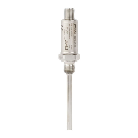
Miniature resistance thermometer, model TR33
Miniatur-Widerstandsthermometer, Typ TR33
Sonde à résistance miniature, type TR33
Termorresistencia miniatura, modelo TR33
70018194
Miniature resistance thermometer, model TR33
Operating instructions
Betriebsanleitung
Mode d'emploi
Manual de instrucciones
EN
DE
FR
ES
Publicité
Chapitres
Table des Matières

Manuels Connexes pour WIKA TR33


Sommaire des Matières pour WIKA TR33
- Page 1 Operating instructions Betriebsanleitung Mode d’emploi Manual de instrucciones Miniature resistance thermometer, model TR33 Miniatur-Widerstandsthermometer, Typ TR33 Sonde à résistance miniature, type TR33 Termorresistencia miniatura, modelo TR33 70018194 Miniature resistance thermometer, model TR33...
- Page 2 Mode d'emploi type TR33 Page 63 - 92 Manual de instrucciones modelo TR33 Página 93 - 122 © 01/2014 WIKA Alexander Wiegand SE & Co. KG All rights reserved. / Alle Rechte vorbehalten. WIKA ® is a registered trademark in various countries.
-
Page 3: Table Des Matières
5. Transport, packaging and storage 6. Commissioning, operation 7. Configuration 8. Configuration software WIKAsoft-TT 9. Connecting PU-548 programming unit 10. Maintenance and cleaning 11. Faults 12. Dismounting, return and disposal Appendix : CSA control drawing Declarations of conformity can be found online at www.wika.com. WIKA operating instructions model TR33... -
Page 4: General Information
Subject to technical modifications. ■ Further information: ■ - Internet address: www.wika.de / www.wika.com - Relevant data sheet: TE 60.33 - Application consultant: Tel.: +49 9372 132-0 Fax: +49 9372 132-406 info@wika.com WIKA operating instructions model TR33... - Page 5 Abbreviations 2-wire The lead resistance is recorded as an error in the measurement. 3-wire With a cable length of 30 m or longer, measuring errors can occur. 4-wire The lead resistance can be neglected. WIKA operating instructions model TR33...
-
Page 6: Safety
2.1 Intended use The model TR33 resistance thermometer is used as a general- purpose thermometer for the measurement of temperatures from -50 … +150 °C or -58 ... +302 °F (without neck tube) and -50 … +250 °C or -58 ... -
Page 7: Personnel Qualification
The skilled electrical personnel must comply with current legal accident prevention regulations. Special operating conditions require further appropriate knowledge, e.g. of aggressive media. WIKA operating instructions model TR33... -
Page 8: Special Hazards
Electrical instruments may only be installed and ■ connected by skilled electrical personnel. Operation using a defective power supply unit (e.g. short ■ circuit from the mains voltage to the output voltage) can result in life-threatening voltages at the instrument! WIKA operating instructions model TR33... -
Page 9: Labelling, Safety Marks
Thermometer with transmitter and 4 ... 20 mA output signal ■ Thermometer with direct sensor output with Pt100 and Pt1000 ■ Serial number, TAG number Before mounting and commissioning the instrument, ensure you read the operating instructions! WIKA operating instructions model TR33... -
Page 10: Specifications
DC 10 ... 30 V Max. permissible residual 10 % generated by U < 3 % ripple of the output ripple current Power supply input Protected against reverse polarity Power supply effect ±0.025 % / V (depending on the power supply) WIKA operating instructions model TR33... - Page 11 3-wire ■ 4-wire ■ Tolerance value of the meas- Class A ■ Class B at 2-wire uring element per IEC 60751 ■ Electrical connection M12 x 1 circular connector (4-pin) For detailed specifications for Pt sensors, see Technical information IN 00.17 at www.wika.com. WIKA operating instructions model TR33...
-
Page 12: Ambient Conditions
5) The stated ingress protection only applies when plugged in using mating connectors that have the appropriate ingress protection. 6) Not tested at UL 7) Dependent on the instrument version 8) Reduced operating pressure when using a compression fitting: Stainless steel: max. 100 bar PTFE: max. 8 bar WIKA operating instructions model TR33... -
Page 13: Design And Function
■ weather. The instrument shall be installed “sun/UV radiation protected”. ■ For further specifications see WIKA data sheet TE 60.33 and the order documentation. 4. Design and function 4.1 Description The model TR33 resistance thermometer consists of a thermowell with a fixed process connection and is screwed directly into the process. - Page 14 1) For process temperature > 150 °C (302 °F) a neck length Height process connection N (M ) of 70 mm is required, otherwise N (M ) selectable Ød Sensor diameter (55, 65 or 70 mm). Thread Height process connection X G 1/2 G 3/8 G 1/4 WIKA operating instructions model TR33...
-
Page 15: Scope Of Delivery
) of 70 mm is required, otherwise N (M ) selectable Ød Sensor diameter (55, 65 or 70 mm). Thread Height process connection X 1/4 NPT 1/2 NPT 4.3 Scope of delivery Cross-check scope of delivery with delivery note. WIKA operating instructions model TR33... -
Page 16: Transport, Packaging And Storage
WARNING! Before storing the instrument (following operation), remove any residual media. This is of particular importance if the medium is hazardous to health, e.g. caustic, toxic, carcinogenic, radioactive, etc. WIKA operating instructions model TR33... -
Page 17: Commissioning, Operation
When there is a non-metallic contact with the vessel, or with its structural components or piping, the instrument must be provided with equipotential bonding. WARNING! Neither repairs nor structural modifications are permitted, and any would void the guarantee. WIKA operating instructions model TR33... -
Page 18: Installation Examples
Stainless steel compression ring 1 ¼ ... 1 ½ PTFE ferrule 1 ¼ ... 1 ½ 6.1.2 Tightening torque for the M12 mating connector or the M12 adapter Select a tightening torque of 0.6 Nm. WIKA operating instructions model TR33... -
Page 19: Electrical Connection
The electrical connection is made via a M12 x 1 (4-pin) circular connector. Output signal Pt100 and Pt1000 (standard) ■ Alternative pin assignments possible. 4 ... 20 mA For further information see order documentation. Accessories: M12 x 1 Pt adapter to DIN EN 175301-803 angular connector M12 x 1 connector Angular connector WIKA operating instructions model TR33... - Page 20 Alternative pin assignments possible. For further information see order documentation. Accessories: M12 x 1 transmitter adapter to DIN EN 175301-803 angular connector M12 x 1 connector Angular connector 4 ... 20 mA Pin assignment angular connector Signal Description 10 ... 30 V not connected not connected WIKA operating instructions model TR33...
- Page 21 NEC (National Electrical Code). Load diagram The permissible load depends on the loop supply voltage. For communication with the instrument with programming unit PU-548, a max. load of 350 Ω is admissible. 1083 Voltage U in V WIKA operating instructions model TR33...
- Page 22 Therefore, in the event of a “true” sensor break or short-circuit, this is also signalled permanently. In the event of a “false” sensor break or short-circuit, the transmitter has the possibility of reverting to measuring mode. WIKA operating instructions model TR33...
- Page 23 3.8 mA 4 mA 20 mA 20.5 mA Error Error 3.8 ... 4 ... 20 mA 20 ... 20.5 mA signalling signalling 4 mA Measuring mode Error signalling Error signalling 3.9 mA 20.4 mA Error limits and permissible measuring range WIKA operating instructions model TR33...
-
Page 24: Configuration
With neck tube -30 ... +250 °C (-22 ... +482 °F) Class B: ■ Without neck tube -50 ... +150 °C (-58 ... +302 °F) With neck tube -50 ... +250 °C (-58 ... +482 °F) WIKA operating instructions model TR33... -
Page 25: Configuration Software Wikasoft-Tt
The selection of the COM port is made automatically. After the connection of a transmitter (using the PU-548), on pressing the “Start” button, the configuration interface is loaded. The configuration interface can only be loaded when an instrument is connected. WIKA operating instructions model TR33... -
Page 26: Configuration Procedure
5. [optional] Activate write protection All subsequent instruments ■ 1. “Loading the instrument data” 2. [optional] Cancel write protection 3. [optional] Change the required parameters, e. g. TAG number 4. “Save to the instrument” 5. [optional] Activate write protection WIKA operating instructions model TR33... -
Page 27: Connecting Pu-548 Programming Unit
9. Connecting PU-548 programming unit 9. Connecting PU-548 programming unit Connection PU-548 ↔ adapter cable with M12 connector TR33 (predecessor, programming unit model PU-448, also compatible) WIKA operating instructions model TR33... -
Page 28: Maintenance And Cleaning
Sensor drift caused by Replace the sensor with a values overtemperature suitable version Sensor drift caused by Analyse the medium chemical attack Erroneous measured Entry of moisture into Use the appropriate IP values (too low) cable protection WIKA operating instructions model TR33... - Page 29 In this case, contact the manufacturer. If a return is needed, follow the instructions given in chapter 12.2 “Return”. WIKA operating instructions model TR33...
-
Page 30: Dismounting, Return And Disposal
12.2 Return WARNING! Strictly observe the following when shipping the instrument: All instruments delivered to WIKA must be free from any kind of hazardous substances (acids, bases, solutions, etc.). When returning the instrument, use the original packaging or a suitable transport package. To avoid damage: 1. Wrap the instrument in an antistatic plastic film. - Page 31 Dispose of instrument components and packaging materials in an environmentally compatible way and in accordance with the country- specific waste disposal regulations. Do not dispose of with household waste. Ensure a proper disposal in accordance with national regulations. WIKA operating instructions model TR33...
-
Page 32: Appendix : Csa Control Drawing
Appendix : CSA control drawing WIKA operating instructions model TR33... - Page 33 3. Technische Daten 4. Aufbau und Funktion 5. Transport, Verpackung und Lagerung 6. Inbetriebnahme, Betrieb 7. Konfiguration 8. Konfigurationssoftware WIKAsoft-TT 9. Programmiereinheit PU-548 anschließen 10. Wartung und Reinigung 11. Störungen 12. Demontage, Rücksendung und Entsorgung Anlage : CSA control drawing Konformitätserklärungen finden Sie online unter www.wika.de. WIKA Betriebsanleitung Typ TR33...
-
Page 34: Allgemeines
Es gelten die allgemeinen Geschäftsbedingungen in den Verkaufsun- ■ terlagen. Technische Änderungen vorbehalten. ■ Weitere Informationen: ■ - Internet-Adresse: www.wika.de / www.wika.com - zugehöriges Datenblatt: TE 60.33 - Anwendungsberater: Tel.: +49 9372 132-0 Fax: +49 9372 132-406 info@wika.de WIKA Betriebsanleitung Typ TR33... -
Page 35: Symbolerklärung
Oberflächen oder Flüssigkeiten zu Verbren- nungen führen kann, wenn sie nicht gemieden wird. Abkürzungen 2-Leiter Der Leitungswiderstand geht als Fehler in die Messung ein. 3-Leiter Ab einer Kabellänge von 30 m können Messabweichungen auftreten. 4-Leiter Der Leitungswiderstand kann vernachlässigt werden. WIKA Betriebsanleitung Typ TR33... -
Page 36: Sicherheit
Kapiteln dieser Betriebsanleitung. 2.1 Bestimmungsgemäße Verwendung Das Widerstandsthermometer Typ TR33 wird als universelles Thermo- meter zum Messen von Temperaturen von -50 … +150 °C bzw. -58 ... + 302 °F (ohne Halsrohr) und -50 … +250 °C bzw. -58 ... +482 °F (mit Halsrohr) in flüssigen und gasförmigen Medien verwendet. - Page 37 Arbeitsumfeld, in dem es tätig ist, ausgebildet und kennt die relevanten Normen und Bestimmungen. Das Elektrofachpersonal muss die Bestimmungen der geltenden gesetzlichen Vorschriften zur Unfall- verhütung erfüllen. Spezielle Einsatzbedingungen verlangen weiteres entsprechendes Wissen, z. B. über aggressive Medien. WIKA Betriebsanleitung Typ TR33...
-
Page 38: Besondere Gefahren
Lebensgefahr. Einbau und Montage des elektrischen Gerätes dürfen nur ■ durch das Elektrofachpersonal erfolgen. Bei Betrieb mit einem defekten Netzgerät (z. B. ■ Kurzschluss von Netzspannung zur Ausgangsspan- nung) können am Gerät lebensgefährliche Spannungen auftreten! WIKA Betriebsanleitung Typ TR33... -
Page 39: Beschilderung, Sicherheitskennzeichnungen
Angaben zur Ausführung (Messelement, Ausgangssignal, Messbereich...) Thermometer mit Messumformer und Ausgangssignal 4 … 20 mA ■ Thermometer mit direktem Sensorausgang mit Pt100 und Pt1000 ■ Seriennummer, TAG-Nummer Vor Montage und Inbetriebnahme des Gerätes unbedingt die Betriebsanleitung lesen! WIKA Betriebsanleitung Typ TR33... -
Page 40: Technische Daten
Ω und U in V Bürdeneinfluss ±0,05 % / 100 Ω Hilfsenergie U DC 10 ... 30 V 10 % von U erzeugt < 3 % Welligkeit des Aus- Max. zulässige Restwelligkeit gangsstromes Hilfsenergieeingang Geschützt gegen Verpolung WIKA Betriebsanleitung Typ TR33... - Page 41 Pt1000 (Messstrom: 0,1 ... 0,3 mA) ■ Schaltungsart 2-Leiter 3-Leiter 4-Leiter ■ ■ ■ Klasse A Grenzabweichung des Mess- ■ elements nach IEC 60751 Klasse B bei 2-Leiter ■ Elektrischer Anschluss M12 x 1-Rundstecker (4-polig) Detaillierte Angaben zu Pt-Sensoren siehe Technische Information IN 00.17 unter www.wika.de. WIKA Betriebsanleitung Typ TR33...
- Page 42 5) Die angegebenen Schutzarten gelten nur im gesteckten Zustand mit Leitungssteckern entsprechender Schutzart. 6) Nicht getestet bei UL 7) Abhängig von der Geräteausführung 8) Reduzierter Betriebsdruck bei Verwendung einer Klemmverschraubung: CrNi-Stahl: max. 100 bar PTFE: max. 8 bar WIKA Betriebsanleitung Typ TR33...
-
Page 43: Aufbau Und Funktion
Gerät in witterungsgeschützten Standorten einbauen. ■ Gerät gegen Sonnen-/UV-Strahlung geschützt einbauen. ■ Weitere technische Daten siehe WIKA-Datenblatt TE 60.33 und Bestell- unterlagen. 4. Aufbau und Funktion 4.1 Beschreibung Das Widerstandsthermometer Typ TR33 besteht aus einem Schutzrohr mit festem Prozessanschluss und wird direkt in den Prozess einge- schraubt. - Page 44 1) Bei Prozesstemperatur > 150 °C (302 °F) ist eine Halslänge Höhe Prozessanschluss N (M ) von 70 mm erforderlich, ansonsten N (M ) wählbar Ød Sensordurchmesser (55, 65 oder 70 mm). Gewinde Höhe Prozessanschluss X G 1/2 G 3/8 G 1/4 WIKA Betriebsanleitung Typ TR33...
-
Page 45: Lieferumfang
1) Bei Prozesstemperatur > 150 °C (302 °F) ist eine Halslänge Höhe Prozessanschluss N (M ) von 70 mm erforderlich, ansonsten N (M ) wählbar Ød Sensordurchmesser (55, 65 oder 70 mm). Gewinde Höhe Prozessanschluss X 1/4 NPT 1/2 NPT 4.3 Lieferumfang Lieferumfang mit dem Lieferschein abgleichen. WIKA Betriebsanleitung Typ TR33... -
Page 46: Transport, Verpackung Und Lagerung
3. Bei längerer Einlagerung (mehr als 30 Tage) einen Beutel mit Trock- nungsmittel der Verpackung beilegen. WARNUNG! Vor der Einlagerung des Gerätes (nach Betrieb) alle anhaf- tenden Messstoffreste entfernen. Dies ist besonders wichtig, wenn der Messstoff gesundheitsgefährdend ist, wie z. B. ätzend, giftig, krebserregend, radioaktiv, usw. WIKA Betriebsanleitung Typ TR33... -
Page 47: Inbetriebnahme, Betrieb
Bei einem nichtmetallischen Kontakt mit dem Behälter oder dessen Konstruktionsteilen bzw. Rohrleitungen muss das Gerät mit einem Poten- tialausgleich versehen werden. WARNUNG! Reparaturen sowie bauliche Veränderungen sind nicht zuläs- sig und führen zur Erlöschung der Garantie. WIKA Betriebsanleitung Typ TR33... - Page 48 ANSI B 1.20 entnehmen. 6.1.1 Anzugsdrehmomente für Klemmverschraubungen Dichtung Umdrehungen Max. Druck in bar Klemmring CrNi-Stahl 1 ¼ ... 1 ½ Schneidring CrNi-Stahl 1 ¼ ... 1 ½ Klemmring PTFE 1 ¼ ... 1 ½ 6.1.2 Anzugsdrehmoment für den M12-Gegenstecker oder den M12-Adapter Anzugsdrehmoment von 0,6 Nm wählen. WIKA Betriebsanleitung Typ TR33...
- Page 49 6. Inbetriebnahme, Betrieb 6.2 Elektrischer Anschluss Der elektrische Anschluss erfolgt über den Rundstecker M12 x 1 (4-polig). Ausgangssignal Pt100 und Pt1000 (Standard) ■ Alternative Anschlussbelegungen möglich. 4 ... 20 mA Weitere Informationen siehe Bestellunterlagen. Zubehör: Pt-Adapter M12 x 1 zu Winkelstecker DIN EN 175301-803 M12 x 1-Stecker Winkelstecker WIKA Betriebsanleitung Typ TR33...
- Page 50 ■ Signal Beschreibung 10 ... 30 V nicht angeschlossen nicht angeschlossen Alternative Anschlussbelegungen möglich. Weitere Informationen siehe Bestellunterlagen. Zubehör: Transmitter-Adapter M12 x 1 zu Winkelstecker DIN EN 175301-803 M12 x 1-Stecker Winkelstecker 4 ... 20 mA Anschlussbelegung Winkelstecker Signal Beschreibung 10 ... 30 V nicht angeschlossen nicht angeschlossen WIKA Betriebsanleitung Typ TR33...
- Page 51 Units“ gemäß CEC (Canadian Electrical Code) oder NEC (National Electrical Code) erfolgen. Bürdendiagramm Die zulässige Bürde hängt von der Spannung der Schleifenversorgung ab. Bei Kommunikation mit dem Gerät, mit Programmiereinheit PU-548, ist eine Bürde von maximal 350 Ω zulässig. 1083 Spannung U in V WIKA Betriebsanleitung Typ TR33...
- Page 52 Messwert auf der Stromschleife ausgegeben. Somit wird im Falle eines „wahren“ Fühlerbruches bzw. Kurzschlusses dieser auch dauerhaft signalisiert. Im Falle eines „falschen“ Fühler- bruches bzw. Kurzschlusses hat der Transmitter die Möglichkeit, wieder in den Messbetrieb zu gelangen. WIKA Betriebsanleitung Typ TR33...
- Page 53 Fehlergrenzen zwischen Fehlersignalisierung und Messmodus hin- und herspringt. 3,8 mA 4 mA 20 mA 20,5 mA Fehlersig- Fehlersig- 3,8 ... 4 ... 20 mA 20 ... 20,5 mA nalisierung nalisierung 4 mA Messmodus Fehlersignalisierung Fehlersignalisierung 3,9 mA 20,4 mA Fehlergrenzen und zulässiger Messbereich WIKA Betriebsanleitung Typ TR33...
-
Page 54: Konfiguration
Ohne Halsrohr -30 ... +150 °C (-22 ... +302 °F) Mit Halsrohr -30 ... +250 °C (-22 ... +482 °F) Klasse B: ■ Ohne Halsrohr -50 ... +150 °C (-58 ... +302 °F) Mit Halsrohr -50 ... +250 °C (-58 ... +482 °F) WIKA Betriebsanleitung Typ TR33... -
Page 55: Konfigurationssoftware Wikasoft-Tt
Länderflagge geändert werden. Die Auswahl des COM-Ports erfolgt automatisch. Nach dem Anschluss eines Transmitters (mit PU-548) kann durch Aktivieren des Start-Buttons die Konfigurationsoberfläche geladen werden. Die Konfigurationsoberfläche kann nur mit einem angeschlossenen Gerät geladen werden. WIKA Betriebsanleitung Typ TR33... - Page 56 4. “In das Gerät speichern” 5. [optional] Schreibschutz aktivieren Alle folgenden Geräte ■ 1. “Gerätedaten laden” 2. [optional] Schreibschutz aufheben 3. [optional] Ändern der gewünschten Parameter, z. B. TAG-Nummer 4. “In das Gerät speichern” 5. [optional] Schreibschutz aktivieren WIKA Betriebsanleitung Typ TR33...
-
Page 57: Programmiereinheit Pu-548 Anschließen
9. Programmiereinheit PU-548 anschließen 9. Programmiereinheit PU-548 anschließen Anschluss PU-548 ↔ Adapterkabel mit Anschluss M12 TR33 (Vorgängermodell, Programmiereinheit Typ PU-448, ebenfalls kompatibel) WIKA Betriebsanleitung Typ TR33... -
Page 58: Wartung Und Reinigung
Kein Signal/ Zu hohe mechanische Ersatz des Fühlers durch eine Leitungsbruch Belastung oder Übertem- geeignete Ausführung peratur Fehlerhafte Sensordrift durch Über- Ersatz des Fühlers durch eine temperatur geeignete Ausführung Messwerte Sensordrift durch chemi- Medium analysieren schen Angriff WIKA Betriebsanleitung Typ TR33... - Page 59 Gerät unverzüglich außer Betrieb zu setzen, sicherzustellen, dass kein Signal mehr anliegt und gegen versehentliche Inbetriebnahme zu schüt- zen. In diesem Falle Kontakt mit dem Hersteller aufnehmen. Bei notwendiger Rücksendung die Hinweise siehe Kapitel 12.2 „Rücksendung“ beachten. WIKA Betriebsanleitung Typ TR33...
-
Page 60: Demontage, Rücksendung Und Entsorgung
Messstoffe. Widerstandsthermometer nur im drucklosen Zustand demontieren! 12.2 Rücksendung WARNUNG! Beim Versand des Gerätes unbedingt beachten: Alle an WIKA gelieferten Geräte müssen frei von Gefahrstof- fen (Säuren, Laugen, Lösungen, etc.) sein. Zur Rücksendung des Gerätes die Originalverpackung oder eine geeig- nete Transportverpackung verwenden. Um Schäden zu vermeiden: 1. - Page 61 „Service“ auf unserer lokalen Internetseite. 12.3 Entsorgung Durch falsche Entsorgung können Gefahren für die Umwelt entstehen. Gerätekomponenten und Verpackungsmaterialien entsprechend den landesspezifischen Abfallbehandlungs- und Entsorgungsvorschriften umweltgerecht entsorgen. Nicht mit dem Hausmüll entsorgen. Für eine geordnete Entsorgung gemäß nationaler Vorgaben sorgen. WIKA Betriebsanleitung Typ TR33...
-
Page 62: Anlage : Csa Control Drawing
Anlage : CSA control drawing WIKA Betriebsanleitung Typ TR33... - Page 63 5. Transport, emballage et stockage 6. Mise en service, utilisation 7. Configuration 8. Logiciel de configuration WIKAsoft-TT 9. Raccordement de l'unité de programmation PU-548 10. Entretien et nettoyage 11. Dysfonctionnements 12. Démontage, retour et mise au rebut Annexe : CSA control drawing Déclarations de conformité disponibles sur www.wika.fr. WIKA mode d'emploi type TR33...
-
Page 64: Généralités
■ Pour obtenir d'autres informations : ■ - Consulter notre site Internet : www.wika.fr - Fiche technique correspondante : TE 60.33 - Conseiller applications : Tel.: +33 1 343084-84 Fax : +33 1 343084-94 info@wika.fr WIKA mode d'emploi type TR33... -
Page 65: Abréviations
La résistance de ligne d'élément de mesure génère une erreur de mesure. 3 fils Avec une longueur de câble de 30 m ou plus, des erreurs de mesure peuvent se produire. 4 fils La résistance de ligne peut être négligée. WIKA mode d'emploi type TR33... -
Page 66: Sécurité
2.1 Utilisation conforme à l'usage prévu La sonde à résistance de type TR33 est à usage général et permet de mesurer des températures allant de -50 ... +150 °C ou de -50 ... +302 °F (sans extension) et de -50 ... +250 °C ou de -50 ... +482 °F (avec extension) dans un process liquide et gazeux. -
Page 67: Qualification Du Personnel
L'électricien qualifié doit satisfaire aux dispositions des prescriptions juridiques en vigueur relatives à la protection contre les accidents. Les conditions d'utilisation spéciales exigent également une connaissance adéquate par exemple des liquides agressifs. WIKA mode d'emploi type TR33... -
Page 68: Dangers Particuliers
être effectué que par un électricien qualifié. En cas d'utilisation avec un instrument d'alimentation ■ défectueux (par exemple court-circuit entre la tension du secteur et la tension de sortie), des tensions présentant un danger de mort peuvent apparaître sur l'instrument ! WIKA mode d'emploi type TR33... -
Page 69: Etiquetage, Marquages De Sécurité
Sonde avec transmetteur et signal de sortie 4 ... 20 mA ■ Sonde avec sortie capteur directe avec Pt100 et Pt1000 ■ Numéro de série, numéro d‘étiquette Lire impérativement le mode d'emploi avant le montage et la mise en service de l'instrument ! WIKA mode d'emploi type TR33... -
Page 70: Spécifications
V Effet de charge ±0,05 % / 100 Ω Alimentation U 10 ... 30 VDC Ondulation résiduelle max. 10 % générée par U < 3 % d'ondulation du admissible courant de sortie Entrée alimentation Protégée contre l'inversion de polarité électrique WIKA mode d'emploi type TR33... - Page 71 Classe B à 2 fils ■ CEI 60751 Raccordement électrique Connecteur circulaire M12 x 1 (4 plots) Pour obtenir des spécifications détaillées sur les capteurs Pt, voir l'information technique IN 00.17 sur www.wika.fr. WIKA mode d'emploi type TR33...
-
Page 72: Conditions Ambiantes
6) Non testé selon le standard UL 7) Dépendant de la version de l’instrument 8) Pression de service réduite lors de l’utilisation d’un raccord coulissant : Acier inox : max. 100 bar PTFE : max. 8 bar WIKA mode d'emploi type TR33... -
Page 73: Brevets, Droits De Propriété
4. Conception et fonction 4.1 Description La sonde à résistance TR33 est constituée d'un doigt de gant avec un raccord process fixe et est vissée directement dans le process. Elle est conçue de manière à résister aux chocs et vibrations, et tous les composants électriques sont protégés contre l'humidité... - Page 74 N (M ) de 70 mm est nécessaire, Ød Diamètre du capteur sinon N (M ) est sélectionnable (55, 65 ou 70 mm). Filetage Hauteur du raccord process X G 1/2 G 3/8 G 1/4 WIKA mode d'emploi type TR33...
-
Page 75: Détail De La Livraison
Diamètre du capteur sinon N (M ) est sélectionnable (55, 65 ou 70 mm). Filetage Hauteur du raccord process X 1/4 NPT 1/2 NPT 4.3 Détail de la livraison Comparer le détail de la livraison avec le bordereau de livraison. WIKA mode d'emploi type TR33... -
Page 76: Transport, Emballage Et Stockage
Enlever tous les restes de fluides adhérents avant l'entreposage de l'instrument (après le fonctionnement). Ceci est particulièrement important lorsque le fluide représente un danger pour la santé, comme p. ex. des substances corrosives, toxiques, cancérogènes, radioactives etc. WIKA mode d'emploi type TR33... -
Page 77: Mise En Service, Utilisation
Lorsqu'il y a un contact non-métallique avec la cuve, avec ses éléments structuraux ou la tuyauterie, l'instrument doit être muni d'une liaison équipotentielle. AVERTISSEMENT ! D'éventuelles réparations ou des modifications structurelles ne sont pas autorisées et entraînent l'annulation de la garantie. WIKA mode d'emploi type TR33... -
Page 78: Exemples D'installation
1 ¼ ... 1 ½ Joint de compression en acier inox 1 ¼ ... 1 ½ Ferrule PTFE 1 ¼ ... 1 ½ 6.1.2 Couple de serrage pour le contre-connecteur M12 ou l‘adaptateur M12 Sélectionner un couple de serrage de 0,6 Nm. WIKA mode d'emploi type TR33... -
Page 79: Raccordement Électrique
M12 x 1 (4 plots). Signaux de sortie Pt100 et Pt1000 (standard) ■ Autres configurations du raccordement possibles. Pour plus d‘informations, voir la documentation de commande. 4 ... 20 mA Accessoires : Adaptateur Pt M12 x 1 raccordé à connecteur coudé DIN EN 175301-803 Connecteur M12 x 1 Connecteur coudé WIKA mode d'emploi type TR33... - Page 80 Autres configurations du raccordement possibles. Pour plus d‘informations, voir la documentation de commande. Accessoires : Adaptateur transmetteur M12 x 1 pour connecteur coudé DIN EN 175301-803 Connecteur M12 x 1 Connecteur coudé 4 ... 20 mA Configuration du raccordement c onnecteur coudé Broche Signal Description 10 ... 30 V non raccordé non raccordé WIKA mode d'emploi type TR33...
- Page 81 Diagramme de charge La charge admissible dépend de la tension d'alimentation de la boucle. Pour la communication avec l'instrument avec l'unité de programmation PU-548, une charge maximale de 350 Ω est autorisée. 1083 Tension U en V WIKA mode d'emploi type TR33...
-
Page 82: Comportement Du Signal De Sortie Électrique 4
Par conséquent, dans le cas d'une “vraie” rupture de capteur ou d'un “vrai” court-circuit, ceci est également signalé de façon permanente. Dans le cas d'une “fausse” rupture de capteur ou d'un “faux” court- circuit, l'émetteur a la possibilité de revenir au mode de mesure. WIKA mode d'emploi type TR33... - Page 83 20,5 mA Signalisation Signalisation 3,8 ... 4 ... 20 mA 20 ... 20,5 mA de défaut de défaut 4 mA Mode de mesure Signalisation de défaut Signalisation de défaut 3,9 mA 20,4 mA Limites d'erreur et étendue de mesure admissible WIKA mode d'emploi type TR33...
-
Page 84: Configuration
Sans extension -30 ... +150 °C (-22 ... +302 °F) Avec extension -30 ... +250 °C (-22 ... +482 °F) Classe B : ■ Sans extension -50 ... +150 °C (-58 ... +302 °F) Avec extension -50 ... +250 °C (-58 ... +482 °F) WIKA mode d'emploi type TR33... -
Page 85: Logiciel De Configuration Wikasoft-Tt
Le port COM est sélectionné automatiquement. Après la connexion d’un transmetteur (à l’aide de la PU-548), l’interface de configuration est chargée en appuyant sur le bouton “Démarrer”. L’interface de configuration ne peut être chargée que lorsqu’un instrument est connecté. WIKA mode d'emploi type TR33... -
Page 86: Procédure De Configuration
4. “Enregistrer sur l‘instrument” 5. [option] Activer la protection en écriture Tous les appareils suivants ■ 1. “Chargement des données instrument” 2. [option] Annuler la protection en écriture 3. [option] Modifier les paramètres requis, par ex. numéro d‘étiquette WIKA mode d'emploi type TR33... -
Page 87: Raccordement De L'unité De Programmation Pu
4. “Enregistrer sur l‘instrument” 5. [option] Activer la protection en écriture 9. Raccordement de l'unité de programmation PU-548 Connexion PU-548 ↔ câble adaptateur avec connecteur M12 TR33 (modèle prédécesseur, unité de programmation type PU-448, également compatible) WIKA mode d'emploi type TR33... -
Page 88: Entretien Et Nettoyage
élevée ou température une exécution adaptée excessive Dérive du capteur causée Remplacer le capteur avec Valeurs mesurées erronées par une température une exécution adaptée excessive Dérive du capteur causée Analyse du fluide par une attaque chimique WIKA mode d'emploi type TR33... - Page 89 Dans ce cas, contacter le fabricant. S‘il est nécessaire de retourner l‘instrument au fabricant, respecter les indications mentionnées au chapitre 12.2 “Retour”. WIKA mode d'emploi type TR33...
-
Page 90: Démontage, Retour Et Mise Au Rebut
été mis hors pression. 12.2 Retour AVERTISSEMENT ! En cas d'envoi de l'instrument, il faut respecter impérativement ceci : Tous les instruments envoyés à WIKA doivent être exempts de toute substance dangereuse (acides, solutions alcalines, solutions, etc.). Pour retourner l'instrument, utiliser l'emballage original ou un emballage adapté pour le transport. Pour éviter des dommages : 1. - Page 91 Ne pas éliminer avec les ordures ménagères. Garantir une élimination correcte selon les prescriptions nationales. WIKA mode d'emploi type TR33...
-
Page 92: Annexe : Csa Control Drawing
Annexe : CSA control drawing WIKA mode d'emploi type TR33... - Page 93 3. Datos técnicos 4. Diseño y función 5. Transporte, embalaje y almacenamiento 6. Puesta en servicio, funcionamiento 7. Configuración 8. Software de configuración WIKAsoft-TT 9. Conectar la unidad de programación PU-548 117 10. Mantenimiento y limpieza 11. Errores 12. Desmontaje, devolución y eliminación de residuos Anexo: CSA control drawing Declaraciones de conformidad puede encontrar en www.wika.es. WIKA manual de instrucciones modelo TR33...
-
Page 94: Información General
Modificaciones técnicas reservadas. ■ Para obtener más informaciones consultar: ■ - Página web: www.wika.es - Hoja técnica correspondiente: TE 60.33 - Servicio técnico: Tel.: +34 933 938-630 Fax: +34 933 938-666 info@wika.es WIKA manual de instrucciones modelo TR33... - Page 95 2 hilos La resistencia del conductor entra en la medición como error. 3 hilos A partir de una longitud de cable de 30 m pueden producirse errores de medición. 4 hilos La resistencia del conductor puede desestimarse. WIKA manual de instrucciones modelo TR33...
-
Page 96: Seguridad
Cumplir las especificaciones técnicas de este manual de instrucciones. Un manejo no apropiado o una utilización del instrumento no conforme a las especificaciones técnicas requiere la inmediata puesta fuera de servicio y la comprobación por parte de un técnico autorizado por WIKA. WIKA manual de instrucciones modelo TR33... -
Page 97: Cualificación Del Personal
Los electricistas profesionales deben cumplir las normativas sobre la prevención de accidentes en vigor. Algunas condiciones de uso específicas requieren conocimientos adicionales, p. ej. acerca de medios agresivos. WIKA manual de instrucciones modelo TR33... -
Page 98: Riesgos Específicos
¡La operación con una fuente de alimentación defectuosa ■ (p. ej. cortocircuito de la tensión de red a la tensión de salida), puede provocar tensiones letales en la cercanía del instrumento! WIKA manual de instrucciones modelo TR33... - Page 99 Termómetro con salida de sensor directa, con Pt100 y Pt1000 ■ Número de serie, número TAG ¡Es absolutamente necesario leer el manual de instrucciones antes del montaje y la puesta en servicio del instrumento! WIKA manual de instrucciones modelo TR33...
-
Page 100: Datos Técnicos
Influencia de la carga ±0,05 % / 100 Ω Alimentación auxiliar U DC 10 ... 30 V Ondulación residual máx. 10 % de U generado < 3 % ondulación de la admisible corriente de salida Entrada de la energía Protección contra polaridad inversa auxiliar WIKA manual de instrucciones modelo TR33... - Page 101 Clase B para 2 hilos ■ IEC 60751 Conexión eléctrica Conector circular M12 x 1 (4-pin) Para consultar más detalles acerca de las sondas Pt, véase la información técnica IN 00.17 en www.wika.es WIKA manual de instrucciones modelo TR33...
-
Page 102: Condiciones Ambientales
6) No ensayado según la norma UL 7) Depende de la versión 8) Presión de trabajo reducida cuando se utiliza un racor de apriete: Acero inoxidable: máx. 100 bar PTFE: máx. 8 bar WIKA manual de instrucciones modelo TR33... -
Page 103: Diseño Y Función
■ El instrumento debe instalarse protegido de la luz solar/radiación ■ ultravioleta. Para más datos técnicos consulte la hoja técnica de WIKA TE 60.33 y la documentación de pedido. 4. Diseño y función 4.1 Descripción Las termorresistencias TR33 se componen de una vaina con conexión fija y se enroscan directamente al proceso. - Page 104 N (M ) de 70 mm, de otro Ød Diámetro del sensor modo se puede seleccionar N (M ) (55, 65 ó 70 mm). Rosca Altura de la conexión a proceso X G 1/2 G 3/8 G 1/4 WIKA manual de instrucciones modelo TR33...
-
Page 105: Volumen De Suministro
Diámetro del sensor modo se puede seleccionar N (M ) (55, 65 ó 70 mm). Rosca Altura de la conexión a proceso X 1/4 NPT 1/2 NPT 4.3 Volumen de suministro Comparar mediante el albarán si se han entregado todas las piezas. WIKA manual de instrucciones modelo TR33... -
Page 106: Transporte, Embalaje Y Almacenamiento
Antes de almacenar el instrumento (después del funcionamiento), eliminar todos los restos de medios adheridos. Esto es especialmente importante cuando el medio es nocivo para la salud, como p. ej. cáustico, tóxico, cancerígeno, radioactivo, etc. WIKA manual de instrucciones modelo TR33... -
Page 107: Puesta En Servicio, Funcionamiento
Si hay un contacto no metálico con el contenedor o sus partes constructivas o la tubería, debe dotarse el instrumento con una conexión equipotencial. ¡ADVERTENCIA! No se permite ningún tipo de reparación ni modificación constructiva, ya que estas modificaciones provocan la anulación de la garantía. WIKA manual de instrucciones modelo TR33... -
Page 108: Pares De Apriete Para Racores De Presión
1 ¼ ... 1 ½ Anillo de corte de acero inoxidable 1 ¼ ... 1 ½ Anillo de apriete de PTFE 1 ¼ ... 1 ½ 6.1.2 Par de apriete para el conector hembra M12 o el adaptador M12 Seleccionar un par de apriete de 0,6 Nm. WIKA manual de instrucciones modelo TR33... -
Page 109: Conexión Eléctrica
La conexión eléctrica se realiza mediante un conector circular M12 x 1 (4-pin). Señal de salida Pt100 y Pt1000 (estándar) ■ Posibilidad de detalles de conexionados alternativos. Para más informaciones véase la documentación de pedido. 4 ... 20 mA Accesorio: Adaptador Pt M12 x 1 a conector angular DIN EN 175301-803 Conector M12 x 1 Conector angular WIKA manual de instrucciones modelo TR33... - Page 110 Posibilidad de detalles de conexionados alternativos. Para más informaciones véase la documentación de pedido. Accesorio: Adaptador de transmisor M12 x 1 a conector angular DIN EN 175301-803 Conector M12 x 1 Conector angular 4 ... 20 mA Detalles del conexionado conector angular Pin Señal Descripción 10 ... 30 V no conectado no conectado WIKA manual de instrucciones modelo TR33...
- Page 111 La carga admisible depende de la tensión del bucle de alimentación. Para la comunicación con el instrumento con unidad de programación PU-548 es admisible una carga máx. de 350 Ω. 1083 Tensión U en V WIKA manual de instrucciones modelo TR33...
-
Page 112: Comportamiento De La Señal De Salida Eléctrica 4
De este modo, si hay realmente un sensor roto o cortocircuito, este será señalizado permanentemente. En caso de una rotura de sensor “erronea”o si no está roto el sensor o si no hay ningún cortocircuito, el transmisor puede reanudar la medición. WIKA manual de instrucciones modelo TR33... - Page 113 Señalización 3,8 ... 4 ... 20 mA 20 ... 20,5 mA de errores de errores 4 mA Modo de medición Señalización de errores Señalización de errores 3,9 mA 20,4 mA Límites de error y rango de medida admisible WIKA manual de instrucciones modelo TR33...
-
Page 114: Configuración
Con tubo de cuello -30 ... +250 °C (-22 ... +482 °F) Clase B: ■ Sin tubo de cuello -50 ... +150 °C (-58 ... +302 °F) Con tubo de cuello -50 ... +250 °C (-58 ... +482 °F) WIKA manual de instrucciones modelo TR33... -
Page 115: Software De Configuración Wikasoft-Tt
La selección del puerto COM se efectúa automáticamente. Después de haber conectado un transmisor (con PU-548) se puede cargar la superficie de configuración activando el botón Inicio. La superficie de configuración sólo puede cargarse con un dispositivo conectado. WIKA manual de instrucciones modelo TR33... -
Page 116: Proceso De La Configuración
3. Modificación de los parámetros deseados 4. “Guardar en el instrumento” 5. [opcional] Activar la protección contra escritura Todos los instrumentos siguientes ■ 1. “Cargar datos del dispositivo” 2. [opcional] Eliminar la protección contra escritura WIKA manual de instrucciones modelo TR33... -
Page 117: Conectar La Unidad De Programación Pu
3. [opcional] Modificación de los parámetros deseados, p. ej. número TAG 4. “Guardar en el instrumento” 5. [opcional] Activar la protección contra escritura 9. Conectar la unidad de programación PU-548 Conexión PU-548 ↔ cable adaptador para conexión M12 TR33 (modelo anterior, unidad de programación modelo PU-448, igualmente compatible) WIKA manual de instrucciones modelo TR33... -
Page 118: Mantenimiento Y Limpieza
Sustituir el sensor o la cable o temperaturas extremas unidad extraíble por una versión adecuada Desviación por Sustituir el sensor o la Valores de medición erróneos sobretemperatura unidad extraíble por una versión adecuada Desviación por ataque Analizar el medio químico WIKA manual de instrucciones modelo TR33... - Page 119 En este caso ponerse en contacto con el fabricante. Si desea devolver el instrumento, observe las indicaciones del capítulo 12.2 “Devolución”. WIKA manual de instrucciones modelo TR33...
-
Page 120: Desmontaje, Devolución Y Eliminación De Residuos
¡Desmontar las termorresistencias sólo si no están sometidas a presión! 12.2 Devolución ¡ADVERTENCIA! Es imprescindible observar lo siguiente para el envío del instrumento: Todos los instrumentos enviados a WIKA deben estar libres de sustancias peligrosas (ácidos, lejías, soluciones, etc.). Utilizar el embalaje original o un embalaje adecuado para la devolución del instrumento. Para evitar daños: 1. - Page 121 Eliminar los componentes de los instrumentos y los materiales de embalaje conforme a los reglamentos relativos al tratamiento de residuos y eliminación vigentes en el país de utilización. No eliminar en las basuras domésticas. Garantizar una eliminación correcta según las prescripciones nacionales. WIKA manual de instrucciones modelo TR33...
-
Page 122: Anexo: Csa Control Drawing
Anexo: CSA control drawing WIKA manual de instrucciones modelo TR33... - Page 123 WIKA operating instructions model TR33...
- Page 124 WIKA subsidiaries worldwide can be found online at www.wika.com. WIKA-Niederlassungen weltweit finden Sie online unter www.wika.de. La liste des filiales WIKA dans le monde se trouve sur www.wika.fr. Sucursales WIKA en todo el mundo puede encontrar en www.wika.es. WIKA Alexander Wiegand SE & Co. KG Alexander-Wiegand-Strasse 30 63911 Klingenberg •...