
Manuels Connexes pour Pioneer AVIC-505


Sommaire des Matières pour Pioneer AVIC-505
- Page 1 Mobile Navigation Unit Unité de navigation automobile AVIC-505 Installation Manual Manuel d’installation...
- Page 2 IMPORTANT INFORMATION ABOUT YOUR NEW MOBILE NAVIGATION SYSTEM AND THIS MANUAL…… • The Pioneer Mobile Navigation System is intended solely as an aid to you in the operation of your vehicle. It is not a substitute for your attentiveness, judgement and care while driving.
-
Page 3: Table Des Matières
Contents IMPORTANT SAFEGUARDS ....3 Installation ..........11 PLEASE READ ALL OF THESE CAUTION ............11 INSTRUCTIONS REGARDING To guard against electromagnetic YOUR MOBILE NAVIGATION interference ..........12 SYSTEM AND RETAIN THEM Before installing and fixing ......12 FOR FUTURE REFERENCE....3 Before using the adhesive tape ...... -
Page 4: Important Safeguards
IMPORTANT SAFEGUARDS PLEASE READ ALL OF THESE INSTRUCTIONS REGARDING YOUR MOBILE NAVIGATION SYSTEM AND RETAIN THEM FOR FUTURE REFERENCE. 1. Read this manual fully and carefully before installing your mobile navigation sys- tem. 2. Keep this manual handy for future reference. 3. - Page 5 6. As with any accessory in your vehicle’s interior, the navigation system should not divert your attention from the safe operation of your vehicle. If you experience difficulty in operating the system or reading the display, please make adjustments while safely parked. 7.
-
Page 6: Connecting The System
Connecting the System CAUTION • Pioneer does not recommend that you install or service your navigation unit yourself. Installing or servicing of the product may expose you to risk of elec- tric shock or other hazards. Refer all installation and servicing of your navi- gation unit to authorised Pioneer service personnel. -
Page 7: Before Installing The Unit
Before installing the unit • This unit is designed for vehicles with a 12-volt battery and negative grounding. Before installing the system (especially in a recreational vehicle, lorry, or bus), check the bat- tery voltage. • Disconnect the negative (–) terminal of the battery to avoid the risk of a short circuit. -
Page 8: Connecting The System
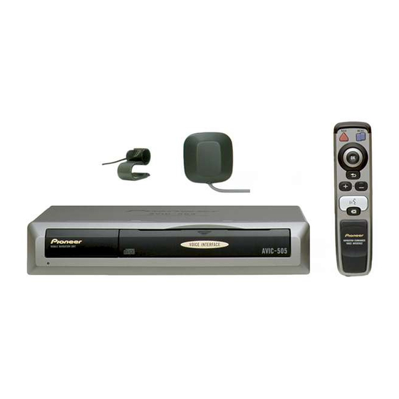
Connecting the System Connecting the system Mobile Navigation Unit AVIC-505 Power cord See Pages 8-10. L O R D IS P L A Color Display AVD-505 RGB cable (supplied) Microphone GPS antenna... -
Page 9: Connecting The Power Cord (1)
Connecting the power cord (1) Mobile Navigation Unit AVIC-505 Power cord GROUND Black To vehicle (metal) body. To keep electromagnetic noise from the vehicle body out of the mobile navigation system, attach this lead near the main unit. Note: When replacing the fuse, be... -
Page 10: Connecting The Power Cord (2)
CAR SPEED SIGNAL INPUT depends on the vehicle model. For details, The mobile navigation system is connected here to detect consult the relevant documents from Pioneer. the distance the vehicle travels. Always connect the When making connections for a model not listed... - Page 11 See Page 8. GUIDE ON Yellow/Black When combining this mobile navigation unit with a Pioneer vehicle stereo, if the vehicle stereo has yellow/black leads (MUTE), connect them to those leads. This way when the guidance audio is output and when you operate the system by voice, the vehicle stereo is automatically muted to reduce the vehicle stereo volume.
-
Page 12: Installation
Installation CAUTION • Pioneer does not recommend that you install or service your navigation unit yourself. Installing or servicing the product may expose you to risk of elec- tric shock or other hazards. Refer all installation and servicing of your navi- gation unit to authorised Pioneer service personnel. -
Page 13: To Guard Against Electromagnetic Interference
CAUTION • It is extremely dangerous to allow the GPS antenna lead or microphone lead to become wound around the steering column or gearstick. Be sure to install the unit in such a way that it will not obstruct driving. •... -
Page 14: Installing The Main Unit
• Install the main unit on a surface with- in 10º tolerance. A surface tilted more than this would increase the errors in location display. 10˚ • If you use the mobile navigation system out of areas where PIONEER is permitted, your position is not shown properly. -
Page 15: Parts Supplied
• Do not install the main unit vertically. Installing it this way can cause it to function improperly. Parts supplied Main unit Mounting angle Screw Tapping screw (2 pcs.) (5 × 8 mm) (6 × 16 mm) (4 pcs.) (4 pcs.) -
Page 16: Installing The Main Unit Inside The Boot
Installation Installing the main unit inside the boot, on the floor under a seat, etc., using tapping screws 1. Fit the mounting brackets to the sides of the main unit. Use the following holes on the mounting brackets. Mounting bracket Screws (5 ×... -
Page 17: Installing The Gps Antenna
Installing the GPS antenna CAUTION • Do not cut the GPS antenna lead to shorten it or use an extension to make it longer. Altering the antenna cable could result in a short circuit. Installation notes • The antenna should be installed on a level surface where radio waves will be blocked as little as possible. -
Page 18: Parts Supplied
Installation Parts supplied GPS antenna Metal sheet Clamp (5 pcs.) Waterproof pad When installing the antenna inside the vehicle (on the dashboard or rear shelf) Affix the metal sheet on as level a surface as possible where the GPS antenna faces outside the window. -
Page 19: Vehicle (On The Dashboard Or Rear Shelf)
When installing the antenna outside the vehicle (on the body) Put the GPS antenna in a position as level as possible, such as on the roof or boot lid. (The GPS antenna is fastened with a magnet.) GPS antenna When routing the lead in from the top of the door Clamps Make a U-shaped loop in the lead... -
Page 20: Installing The Commander
Installation Installing the commander Parts supplied Commander Alkaline battery Velcro tape (large) Velcro tape (small) (UM-4, LR03 1.5 V) (Soft side) (Rough side) (2 pcs.) (2 pcs.) Loading the batteries Supplied alkaline batteries (UM-4, LR03 1.5 V) Battery notes • Be sure that the batteries are loaded with the positive (+) and negative (–) terminals in their correct positions. -
Page 21: Installing The Commander With Velcro Tape
Installing the commander with velcro tape Affix the small pieces of Velcro tape provided (rough side) to the rear surface of the com- mander, and the large piece of Velcro tape (soft side) to the installation surface. Velcro tapes (small) (Rough side) Rear of commander Affix the Velcro tapes where it will... -
Page 22: Installing The Microphone
Installation Installing the microphone Installation notes • Install the microphone in a position and orientation that will enable it to pick up the voice of the person operating the system. Parts supplied Microphone Microphone clip Double-sided tape Clamp (5 pcs.) -
Page 23: When Installing The Microphone On The Sun Visor
When installing the microphone on the sun visor 1. Install the microphone on the microphone clip. Microphone Microphone clip 2. Install the microphone clip on the sun visor. With the sun visor up, install the microphone clip. (Lowering the sun visor reduces the recognition rate for voice operations.) Microphone clip Clamps... -
Page 24: When Installing The Microphone On The Steering Column
Installation When installing the microphone on the steering column 1. Install the microphone on the microphone clip. Fit the microphone lead into the groove. Microphone Microphone clip 2. Install the microphone clip on the steering column. Double-sided tape Clamps Use clamps to secure the Install the microphone clip on lead where necessary inside the rear side of the steering... -
Page 25: After Installing The Unit
After installing the unit 1. Reconnecting the battery. First, double-check that all connections are correct and that the unit is installed correctly. Reassemble all vehicle components that you previously removed. Then reconnect the neg- ative (–) cable to the negative (–) terminal of the battery. 2. - Page 26 INFORMACIÓN IMPORTANTE ACERCA DE SU NUEVO SISTEMA DE NAVEGACIÓN MÓVIL Y ESTE MANUAL • El sistema de navegación móvil Pioneer sólo tiene la finalidad de servirle como ayuda para manejar su vehículo. De ninguna forma debe considerarse como un acaparador de su atención, buen juicio y cuidado durante la conducción.
- Page 27 Índice PRECAUCIÓNES IMPORTANTES ....3 Instalación ..........11 LEA TODAS ESTAS INSTRUCCIONES PRECAUCIÓN ..........11 RELACIONADAS CON SU SISTEMA Para impedir que entre ruido DE NAVEGACIÓN MÓVIL Y electromagnético en el sistema de GUÁRDELAS PARA EMPLEARLAS navegación móvil ........12 COMO REFERENCIA EN EL Antes de instalar y fijar la unidad ....
-
Page 28: Precauciónes Importantes
PRECAUCIÓNES IMPORTANTES LEA TODAS ESTAS INSTRUCCIONES RELACIONADAS CON SU SISTEMA DE NAVEGACIÓN MÓVIL Y GUÁRDELAS PARA EMPLEARLAS COMO REFERENCIA EN EL FUTURO. 1. Lea completa y cuidadosamente este manual antes de instalar su sistema de nave- gación móvil. 2. Guarde a mano este manual para utilizarlo como referencia en el futuro. 3. - Page 29 6. Al igual que con cualquier otro accesorio del interior, el sistema de navegación nunca deberá distraerle y poner en peligro el manejo seguro de su vehículo. Si encuentra dificultades al utilizar el sistema o al leer la visualización, haga los ajustes necesarios estando el vehículo estacionado en un lugar seguro.
-
Page 30: Conexión Del Sistema
Conexión del sistema PRECAUCIÓN • Pioneer no recomienda que sea usted mismo quien instale o revise su unidad de navegación. La instalación o revisión del producto puede exponerle a descargas eléctricas u otros peligros. Solicite que todos los trabajos de insta- lación y revisión de su unidad de navegación los realice el personal de servi-... -
Page 31: Antes De Instalar La Unidad
Antes de instalar la unidad • Esta unidad ha sido diseñada para funcionar en vehículos con una batería de 12 voltios y puesta a masa negativa. Antes de instalar el sistema (especialmente en un vehículo recreativo, camión o autobús), compruebe la tensión de la batería. •... -
Page 32: Conexión Del Sistema
Conexión del sistema Conexión del sistema Unidad de navegación móvil AVIC-505 Cable de alimentación Consulte las páginas 8-10 L O R D IS P L A Pantalla en color AVD-505 Cable RGB (suministrado con este sistema) Micrófono Antena GPS... -
Page 33: Conexión Del Cable De Alimentación (1)
Conexión del cable de alimentación (1) Unidad de navegación móvil AVIC-505 Cable de alimentación MASA A la carrocería (metal) del vehículo. Para impedir que Negro entre en el sistema de navegación móvil el ruido elec- tromagnético procedente de la carrocería, haga la pues- ta a masa cerca de la unidad principal. -
Page 34: Conexión Del Cable De Alimentación (2)
Para conocer detalles, consulte los documentos tar la distancia que ha recorrido el automóvil. Conecte relevantes de Pioneer. Cuando haga las conex- siempre el circuito de detección de velocidad del automóvil iones para un modelo que no se encuentre lis-... - Page 35 Amarillo/Negro Cuando se combine esta unidad de navegación móvil con un equipo estéreo Pioneer para automóvil, si el equipo estéreo tiene cables ama- rillos/negros (SILENCIAMIENTO), haga la conexión a estos cables. De esta forma, cuando salga el audio guía y cuando utilice el sistema medi- ante voz, el equipo estéreo para automóvil se silenciará...
-
Page 36: Instalación
Instalación PRECAUCIÓN • Pioneer no recomienda que sea usted mismo quien instale o revise su unidad de navegación. La instalación o revisión del producto puede exponerle a descargas eléctricas u otros peligros. Solicite que todos los trabajos de insta- lación y revisión de su unidad de navegación los realice el personal de servi- cio Pioneer autorizado. -
Page 37: Para Impedir Que Entre Ruido Electromagnético En El Sistema De Navegación Móvil
PRECAUCIÓN • Es peligrosísimo dejar que el cable de la antena GPS y el cable del micrófono se enrollen en la base del volante o en la palanca de cambios. Asegúrese de instalar la unidad de forma que ésta no sea un obstáculo para la conducción. •... -
Page 38: Instalación De La Unidad Principal
10°. Una superficie más inclinada podría aumentar el error de la visualización de la ubicación. 10˚ • Si utiliza el sistema de navegación móvil fuera de las áreas permitidas por PIONEER, su posición no se mostrará correctamente. -
Page 39: Partes Suministradas
• No instale la unidad principal vertical- mente. Instalarla de esta forma puede ser la causa de que la unidad funcione mal. Partes suministradas Unidad principal Pieza angular de Tornillo Tornillo autor- montaje (5 × 8 mm) roscante (2 piezas) (4 piezas) (6 ×... -
Page 40: Cuando Instale La Unidad Principal En El
Instalación Cuando instale la unidad principal en el maletero, en el suelo debajo de un asiento, etc., utilizando tornillos autorroscantes 1. Ponga las piezas angulares de montaje en los lados de la unidad principal. Utilice los agujeros sigu- ientes de las piezas angu- lares de montaje. -
Page 41: Instalación De La Antena Gps
Instalación de la antena GPS PRECAUCIÓN • No corte el cable de antena de GPS para reducir su longitud ni utilice una extensión para alargarlo. La alteración del cable de la antena puede causar un cortocircuito. Notas acerca de la instalación •... -
Page 42: Partes Suministradas
Instalación Partes suministradas Antena GPS Hoja de metal Abrazadera (5 piezas) Almohadilla para el techo Cuando instale la antena en el interior del vehículo (en el salpicadero o en la bandeja trasera) Fije la hoja de metal en una superficie tan plana como sea posible y donde la antena apunte hacia al exterior de la ventana. -
Page 43: Del Vehículo
Cuando instale la antena en el exterior del vehículo (en la carrocería) Ponga la antena GPS en un lugar tan nivelado como sea posible como, por ejemplo, el techo o la cubierta del maletero. (La antena GPS se fija con su imán.) Antena GPS Cuando pase el cable al interior por la parte superior de la puerta... -
Page 44: Instalación Del Mando A Distancia
Instalación Instalación del mando a distancia Partes suministradas Mando a distancia Pila alcalina Cinta Velcro Cinta Velcro (UM-4, LR03, 1,5 V) (grande) (pequeña) (2 piezas) (Lado blando) (Lado basto) (2 piezas) Instalación de las pilas Pilas alcalinas suministradas (UM-4, LR03, 1,5 V) Notas acerca de la pilas •... -
Page 45: Notas Sobre El Manejo Del Mando A
Instalación del mando a distancia con cinta Velcro Fije las piezas pequeñas de cinta Velcro suministradas (lado basto) en la superficie trasera del mando a distancia, y la pieza grande de cinta Velcro (lado blando) en la superficie de instalación. Cintas Velcro (pequeñas) (Lado basto) Parte trasera del mando a... -
Page 46: Instalación Del Micrófono
Instalación Instalación del micrófono Notas acerca de la instalación • Instale el micrófono en una posición u orientación que permita captar bien las voces de la persona que utilice el sistema mediante voz. Partes suministradas Micrófono Presilla de micrófono Cinta con adhesivo Abrazadera en dos lados (5 piezas) -
Page 47: Cuando Instale El Micrófono En El
Cuando instale el micrófono en el parasol 1. Instale el micrófono en la presilla de micrófono. Micrófono Presilla de micrófono 2. Instale la presilla de micrófono en el parasol. Con el parasol hacia arriba, instale la presilla del micrófono. (Al bajar el parasol se reduce la capacidad de reconocimiento para las operaciones mediante voz.) Presilla de micrófono Abrazaderas... -
Page 48: Cuando Instale El Micrófono En La Base Del Volante
Instalación Cuando instale el micrófono en la base del volante 1. Instale el micrófono en la presilla de micrófono. Fije el cable del micrófono en la ranura. Micrófono Presilla de micrófono 2. Instale la presilla de micrófono en la base del volante. Cinta con adhesivo Abrazaderas en dos lados... -
Page 49: Después De Instalar La Unidad
Después de instalar la unidad 1. Vuelva a conectar la batería. Primero, cerciórese de que todas las conexiones estén bien hechas y de que la unidad esté instalada correctamente. Vuelva a instalar todos los componentes del vehículo que extrajo previamente. Y luego vuelva a conectar el cable negativo (–) al borne negativo (–) de la batería. - Page 50 Aufmerksamkeit des Fahrers nicht vom Verkehrsgeschehen ablenkt: Das Gerät darf den Fahrer niemals von der Einhaltung wichtiger Sichheitsrichtlinien und der allgemeinen Verkehrsregeln abhalten. • Verwenden Sie das Navigationssystem nur an Orten, die von PIONEER zugelassen sind. • Diese Anleitung erklärt den Einbau des mobilen Navigationsystems in Ihren Wagen.
- Page 51 Inhalt WICHTIGE SICHERHEITSHINWEISE..3 Einbau ............11 BITTE LESEN SIE DIESE ANLEITUNG VORSICHTSMASSNAHME ......11 ZUM EINBAU DES MOBILEN Zur Vermeidung elektromagnetischen NAVIGATIONSSYSTEMS Rauschens des mobilen AUFMERKSAM DURCH UND Navigationsystems ........12 BEWAHREN SIE DIE ANLEITUNG FÜR Vor Einbau und Befestigung ......12 SPÄTERES NACHSCHLAGEN AUF.
-
Page 52: Wichtige Sicherheitshinweise
WICHTIGE SICHERHEITSHINWEISE BITTE LESEN SIE DIESE ANLEITUNG ZUM EINBAU DES MOBILEN NAVIGATIONSSYSTEMS AUFMERKSAM DURCH UND BEWAHREN SIE DIE ANLEITUNG FÜR SPÄTERES NACHSCHLAGEN AUF. 1. Bitte lesen Sie diese Anleitung vor dem Einbau des mobilen Navigationsystems aufmerksam durch. 2. Bewahren Sie die Anleitung für späteres Nachschlagen auf. 3. - Page 53 6. Zubehör im Innenraum des Fahrzeugs sollte die Aufmerksamkeit des Fahrers niemals vom Verkehrsgeschehen ablenken, und das gleiche gilt auch für das Navigationsystem. Falls Schwierigkeiten hinsichtlich der Bedienung des Geräts auftreten, oder das angezeigte Bild schlecht erkennbar ist, sollten weitere Einstellungen erst nach dem sicheren Parken des Fahrzeugs vorgenommen wer- den.
-
Page 54: Anschluß Des Geräts
Anschluß des Geräts VORSICHTSMASSNAHME • Pioneer rät nachdrücklich davon ab, das Navigationgerät eigenhändig einzubauen oder zu warten, da hierbei die Möglichkeit elektrischer Schläge und anderer Gefahren besteht. Einbau und Wartung des Navigationsgeräts sind deshalb dem autorisierten Kundendienst-Fachpersonal zu überlassen. • Unsachgemäßer Einbau kann zum Erlöschen der Garantie des Fahrzeugherstellers führen. -
Page 55: Vor Dem Einbau Des Geräts
Vor dem Einbau des Geräts • Das Navigationgerät ist für Fahrzeuge mit 12-Volt-Batterien und negativer Masse bes- timmt. Vor dem Einbau des Geräts zuerst die Batteriespannung überprüfen (gilt beson- ders für Freizeitfahrzeuge, Laster und Busse). • Zur Vermeidung der Kurzschlußgefahr das an den Negativpol (–) der Batterie angeschlossene Batteriekabel trennen. -
Page 56: Anschluß Des Geräts
Anschluß des Geräts Anschluß des Geräts Mobiles Navigationgerät AVIC-505 Betriebsstromkabel Siehe Seite 8 bis 10. L O R D IS P L A Farbdisplay AVD-505 RGB-Kabel (mitgeliefert) Mikrofon GPS-Antenne... -
Page 57: Anschluß Des Betriebsstromkabels (1)
Anschluß des Betriebsstromkabels (1) Mobiles Navigationgerät AVIC-505 Betriebsstromkabel Masse An Fahrzeugkarosserie (Metall) anschließen. In der Schwarz Nähe des Hauptgeräts verlegen, um zu vermeiden, daß elektromagnetisches Rauschen von der Fahrzeugkarosserie auf das mobile Navigationsystem übertragen wird. Hinweis: Beim Austauschen der Sicherung immer sicherstellen, daß... -
Page 58: Anschluß Des Betriebsstromkabels (2)
Erkennungsschaltung (Speed Pulse) hängt vom Durch diesen Anschluß erkennt das mobile Fahrzeug ab. Einzelheiten entnehmen Sie aus Navigationsystem die Länge der Fahrtstrecke. Die den entsprechenden Pioneer-Unterlagen. Wenn Geschwindigkeit-Erkennungsschaltung (Speed Pulse) des Verbindungen für in diesen Unterlagen nicht Wagens oder den als Sonderzubehör erhältlichen... - Page 59 Betriebsstromkabel Schwarz, Orange, Rot, Gelb Siehe Seite 8. WEGWEISER-EMPFANG Falls das mobile Navigationsgerät mit einer Pioneer- Gelb/Schwarz Autostereoanlage kombiniert werden soll und die Stereoanlage über Gelb/Schwarz-Kabel zur Stummschaltung (MUTE) verfügt, an diese Kabel anschließen. Hierdurch wird die Lautstärke der Stereoanlage...
-
Page 60: Einbau
Einbau VORSICHTSMASSNAHME • Pioneer rät nachdrücklich davon ab, das Navigationsgerät eigenhändig einzubauen oder zu warten, da hierbei die Möglichkeit elektrischer Schläge und anderer Gefahren besteht. Einbau und Wartung des Navigationsgeräts sind deshalb dem autorisierten Kundendienst-Fachpersonal zu überlassen. • Für den Einbau des Geräts sind die folgenden Plätze unbedingt zu vermei- den: * Plätze, an denen das Gerät bei einem plötzlichen Bremsmanöver Fahrer... -
Page 61: Zur Vermeidung Elektromagnetischen Rauschens Des Mobilen Navigationsystems
VORSICHTSMASSNAHME • Es ist äußerst gefährlich die GPS-Antennenleitung oder das Mikrofonkabel um die Lenksäule oder den Gangschalthebel zu wickeln. Beim Einbau un bedingt darauf achten, daß das Gerät den Fahrer nicht behindert. • Vergewissern, daß sich die Kabel nicht in der Tür oder im Sitzverstell- mechanismus verfangen können und einen Kurzschluß... -
Page 62: Einbau Der Navigationseinheit
• Die Navigationseinheit auf einer ebe- nen Fläche einbauen, deren Neigungsgrad 10° nicht überschreiten sollte. Eine schrägere Fläche kann zu einer erhöhten Fehlerrate der Fahrzeugpositionsanzeige führen. 10˚ • Bei Verwendung des mobilen Navigationsystems außerhalb des Zulassungsbereichs von PIONEER, wird die Fahrzeugposition nicht korrekt angezeigt. -
Page 63: Mitgelieferte Teile
• Die Navigationseinheit nicht vertikal aufgestellt einbauen. Der Einbau in dieser Stellung kann zu Funktionsstörungen des Gerätes führen. Mitgelieferte Teile Navigationseinheit Winkelblech Schraube Schneidschraube (2 Stck.) (5 × 8 mm) (6 × 16 mm) (4 Stck.) (4 Stck.) -
Page 64: Einbau Der Navigationseinheit Im
Einbau Einbau der Navigationseinheit im Kofferraum, auf dem Boden unter dem Sitz usw. mitSchneidschrauben 1. Die Winkelbleche an die Seiten der Navigationseinheit anschrauben. Die folgenden Löcher im Winkelblech verwenden. Winkelblech Schrauben (5 × 8 mm) 2. Mit Schneidschrauben am Boden festschrauben. Schneidschrauben (6 ×... -
Page 65: Einbau Der Gps-Antenne
Einbau der GPS-Antenne VORSICHTSMASSNAHME • Das Kabel der GPS-Antenne nicht abschneiden, um es zu kürzen, oder mit einem Verlängerungskabel verlängern, da beides zu einem Kurzschluß führen kann. Hinweise zur Befestigung • Die Antenne ist auf einer ebenen Fläche zu befestigen, die für Radiowellen gut zugänglich sein sollte. -
Page 66: Mitgelieferte Teile
Einbau Mitgelieferte Teile GPS-Antenne Metallblech Kabelklemme (5 Stck.) Wasserfestes Polster Einbau der Antenne im Fahrzeuginnenraum (auf dem Armaturenbrett oder der Heckablage) Das Metallblech auf einer möglichst ebenen Fläche befestigen, an der die GPS-Antenne nach außen gerichtet ist. Die GPS-Antenne auf dem Metallblech plazieren. (Die Befestigung erfolgt durch Magnethaftung.) GPS-Antenne Metallblech... -
Page 67: Fahrzeuginnenraum
Einbau der Antenne außen am Fahrzeug (an der Karosserie) Die GPS-Antenne auf einer möglichst ebenen Fläche anbringen, wie z.B. auf dem Dach oder dem Kofferraumdeckel. (Die Befestigung erfolgt durch Magnethaftung.) GPS-Antenne Verlegen der Leitung vom Dach in den Fahrzeuginnenraum Kabelklemmen Die Antennenleitung hier in einer Die Antennenleitung U-förmigen Schleife verlegen, um... -
Page 68: Einbau Des Bedienungsteils
Einbau Einbau des Bedienungsteils Mitgelieferte Teile Bedienungsteil Alkalibatterien Klettband Klettband (UM-4, LR03, 1,5 V) (groß) (klein) (2 Stck.) (weiche Seite) (rauhe Seite) (2 Stck.) Einlegen der Batterien Mitgelieferte Alkalibatterien (UM-4, LR03, 1,5 V) Hinweise zu den Batterien • Darauf achten, die Batterien mit korrekt ausgerichtetem Plus- (+) und Minuspol (–) einzulegen. -
Page 69: Befestigung Des Bedienungsteils Mit
Befestigung des Bedienungsteils mit Klettband Die mitgelieferten kleinen Klettbandstücke (rauhe Seite) an der Rückseite des Bedienungsteils und das große Klettenbandstück (weiche Seite) auf der Befestigungsfläche anbringen. Klettband (klein) (rauhe Seite) Rückseite des Bedienungsteils Klettband (groß) (weiche Seite) Die Klettbandstücke so anbringen, daß... -
Page 70: Einbau Des Mikrofons
Einbau Einbau des Mikrofons Hinweise zum Einbau • Das Mikrofon an einem geeigneten Platz anbringen und so ausrichten, daß es die Stimme der Person, die das System sprachbedient, gut aufnimmt. Mitgelieferte Teile Mikrofon Mikrofonklemmhalter Doppelseitiger Kabelklemme Klebestreifen (5 Stck.) - Page 71 Befestigung des Mikrofons an der Sonnenblende 1. Das Mikrofon im Mikrofonklemmhalter befestigen. Mikrofon Mikrofonklemmhalter 2. Den Mikrofonklemmhalter an der Sonnenblende anklemmen. Die Sonnenblende hochklappen und den Mikrofonklemmhalter anklemmen. (Ein Herunterklappen der Sonnenblende verringert die Empfangsempfindlichkeit des Mikrofons bei der sprachgesteuerten Bedienung.) Mikrofonklemmhalter Kabelklemmen Das Mikrofonkabel mit...
- Page 72 Einbau Befestigung des Mikrofons an der Lenksäule 1. Das Mikrofon im Mikrofonklemmhalter befestigen. Das Mikrofonkabel in die Kerbe einpassen. Mikrofon Mikrofonklemmhalter 2. Das Mikrofon an der Lenksäule befestigen. Doppelseitiger Klebestreifen Kabelklemmen Das Mikrofonkabel mit Den Mikrofonklemmhalter Kabelklemmen im an der Rückseite der Fahrzeuginnenraum verlegen.
-
Page 73: Nach Dem Einbau Des Geräts
Nach dem Einbau des Geräts 1. Wiederanschließen der Batterie. Vergewissern, daß alle Anschlüsse in Ordnung sind und das Gerät korrekt eingebaut ist. Hiernach alle zuvor ausgebauten Fahrzeugteile wieder befestigen. Anschließend das nega- tive (–) Batteriekabel wieder an den Negativpol (–) der Fahrzeugbatterie anschließen. 2. - Page 74 à toutes les réglementations routières en vigueur. • Utilisez votre système de navigation PIONEER uniquement dans les régions où il est autrisé. • Ce manuel vous explique comment installer cette unité de navigation automobile dans votre voiture.
- Page 75 Table des matières IMPORTANTES MESURES DE Installation ..........11 SECURIT ..........3 ATTENTION ..........11 Pour protéger le système de navigation VEUILLEZ LIRE TOUTES LES contre les parasites électromagnétiques ..12 EXPLICATIONS RELATIVES Avant un branchement définitif......12 À VOTRE SYSTÈME DE Avant d’employer le ruban adhésif ....
-
Page 76: Importantes Mesures De Securit
3. Tenez compte de tous les avertissements formulés dans ce manuel et respectez soigneusement les consignes. 4. Ce Système de Navigation Automobile Pioneer est destiné uniquement à vous aider dans la conduite de votre véhicule. En aucun cas, il n’autorise un relâche- ment de votre attention, de votre jugement et de votre vigilance pendant la con- duite. - Page 77 6. Comme tout autre accessoire de l’habitacle, le système de navigation ne peut pas détourner votre attention et nuire à la sécurité de la conduite. Si vous éprouvez des difficultés à utiliser le système ou à lire l’écran, effectuez les réglages néces- saires après vous être garé...
-
Page 78: Branchement Du Système
Branchement du système ATTENTION • Pioneer déconseille d’installer ou d’entretenir vous-même votre unité de na- vigation car ces travaux comportent des risques d’électrocution et d’autres dangers. Confiez l’installation et l’entretien à un personnel de service Pioneer qualifié. • Immobilisez tous les fils avec des colliers ou des serre-câbles. Ne laissez aucun fil à... -
Page 79: Avant De Raccorder L'appareil
Avant de raccorder l’appareil • Cette unité est conçue pour des véhicules à batterie de 12 volts et mise à la masse néga- tive. Avant d’installer le système (surtout dans un véhicule tout-terrain, camion ou bus), vérifiez la tension de la batterie. •... -
Page 80: Branchement Du Système
Branchement du système Branchement du système Unité de navigation automobile AVIC-505 Cordon d’alimentation Cf. pages 8-10. L O R D IS P L A Ecran couleur AVD-505 Câble RVB (fourni avec ce système) Microphone Antenne GPS... -
Page 81: Branchement Du Cordon D'alimentation (1)
Branchement du cordon d’alimentation (1) Unité de navigation automobile AVIC-505 Cordon d’alimentation MASSE A la carrosserie (partie métallique) du véhicule. Pour Noir éviter que le système de navigation ne soit perturbé par des parasites électromagnétiques, raccordez le fil près de l’unité principale. -
Page 82: Branchement Du Cordon D'alimentation (2)
Le système de navigation est raccordé ici afin de véhicule. Pour des détails, consultez les do- détecter la distance parcourue par la voiture. Raccordez cuments appropriés de Pioneer. Pour toujours le circuit de détection de vitesse de la voiture effectuer les connexions sur un modèle ne ou le générateur d’impulsions de vitesse ND-PG1,... - Page 83 Jaune/Noir Au cas où l’unité de navigation automobile est combinée à une auto- stéréo Pioneer, si celle-ci possède des fils jaune/noir (Mise en sour- dine), effectuez le branchement sur ces fils. De cette façon, quand le guidage sonore est en service et lors d’une commande vocale, le son de l’auto-stéréo est automatiquement atténué...
-
Page 84: Installation
Installation ATTENTION • Pioneer déconseille d’installer ou d’entretenir vous-même votre unité de na- vigation car ces travaux comportent des risques d’électrocution et d’autres dangers. Confiez l’installation et l’entretien à un personnel de service Pioneer qualifié. • N’installez jamais l’unité dans un endroit où: * il pourrait blesser le conducteur ou les passagers en cas d’arrêt brusque;... -
Page 85: Pour Protéger Le Système De Navigation Contre Les Parasites Électromagnétiques
ATTENTION • Une situation très dangereuse pourrait se présenter si le câble d’antenne GPS ou le fil du microphone devait s’enrouler autour de la colonne de direc- tion ou du levier des vitesses. Veillez à installer l’appareil de telle sorte que rien ne fasse obstacle à... -
Page 86: Installation De L'unité Principale
10°; faute de quoi l’erreur d’affichage de la position du véhicule augmenterait. 10˚ • Si vous utilisez le système de navigation automobile hors des régions où PIONEER est autorisé, votre position ne sera pas indiquée correctement. -
Page 87: Pièces Fournies
• N’installez pas l’unité principale verti- calement car elle ne fonctionnerait pas correctement. Pièces fournies Unité principale Applique de montage Vis taraudeuse (2 pièces) (5 × 8 mm) (6 × 16 mm) (4 pièces) (4 pièces) -
Page 88: Installation Dans Le Coffre, Sur Le Tapis
Installation Installation dans le coffre, sur le tapis, sous un siège, etc. avec les vis taraudeuses 1. Fixez les appliques de montage sur les deux côtés de l’unité principale. Utilisez les trous indiqués sur les appliques de montage. Applique de montage Vis (5 ×... -
Page 89: Installation De L'antenne Gps
Installation de l’antenne GPS ATTENTION • Ne coupez pas le câble de l’antenne GPS et n’utilisez pas un prolongateur pour l’allonger car une telle modification pourrait provoquer un court-cir- cuit. Remarques sur l’installation • L’antenne doit être installée sur une surface à... -
Page 90: Pièces Fournies
Installation Pièces fournies Antenne GPS Plaque métallique Serre-fils (5 pièces) Coussin étanche Installation de l’antenne dans le véhicule (sur planche de bord ou lunette arrière) Fixez la plaque métallique sur une surface aussi plate que possible où l’antenne GPS sera dirigée vers une vitre. -
Page 91: Installation De L'antenne À L'extérieur Du
Installation de l’antenne à l’extérieur du véhicule (sur la carrosserie) Posez l’antenne GPS sur une surface aussi plate que possible, telle que le toit ou le capot du coffre. (L’antenne GPS est immobilisée par son propre aimant.) Antenne GPS Cheminement du câble sur le haut de la portière Effectuez une boucle en U avec le Serre-fils... -
Page 92: Installation De La Télécommande
Installation Installation de la télécommande Pièces fournies Télécommande Pile alcaline Bande velcro Bande velcro (UM-4, LR03, 1,5 V) (grande) (petite) (2 pièces) (Côté souple) (Côté rugueux) (2 pièces) Insertion des piles Piles alcalines fournies (UM-4, LR03, 1,5 V) Remarques sur les piles •... -
Page 93: Remarques Sur Le Maniement De La
Fixation de la télécommande avec la bande velcro Fixez les petits morceaux des bandes velcro fournies (côté rugueux) sur l’arrière de la télé- commande et le grand morceau de bande velcro (côté souple) sur la surface d’installation. Bandes velcro (petites) (Côté... -
Page 94: Installation Du Microphone
Installation Installation du microphone Remarques sur l’installation • Installez et orientez le microphone à un endroit où il pourra bien capter la voix de la per- sonne qui commande le système par la voix. Pièces fournies Microphone Attache du microphone Bande adhésive Serre-fils double face... -
Page 95: Installation Du Microphone Sur Le
Installation du microphone sur le pare-soleil 1. Fixez le microphone sur l’attache fournie. Microphone Attache 2. Fixez l’attache du microphone sur le pare-soleil. Le pare-soleil étant relevé, fixez l’attache du microphone. (Le taux de reconnaissance vocale diminue quand le pare-soleil est abaissé.) Attache de microphone Serre-fils A utiliser pour fixer le fil... -
Page 96: Installation Du Microphone Sur La Colonne De Direction
Installation Installation du microphone sur la colonne de direction 1. Fixez le microphone sur l’attache fournie. Cheminer le fil du microphone dans la rainure. Microphone Attache 2. Fixez l’attache du microphone sur la colonne de direction. Bande adhésive double face Serre-fils A utiliser pour fixer le fil Installez l’attache de... -
Page 97: Après Installation De L'unité
Après installation de l’unité 1. Branchement de la batterie. Vérifiez une nouvelle fois que toutes les connexions ont été bien faites et que l’unité est correctement installée. Remontez tous les composants du véhicule qui ont été déposés, puis rebranchez le câble négatif (–) sur la borne négative (–) de la batterie. 2. - Page 98 INFORMAZIONI IMPORTANTI USO DEL SISTEMA DI NAVIGAZIONE MOBILE E DI QUESTO MANUALE • Il sistema di navigazione mobile Pioneer è inteso solo come un aiuto nella guida del veicolo. Non devono mancare attenzione, giudizio e cautela del conducente durante la guida.
- Page 99 Indice MISURE DI SICUREZZA IMPORTANTI ..3 Installazione ..........11 LEGGERE TUTTE QUESTE ISTRUZIONI PRECAUZIONE ..........11 RIGUARDANTI IL SISTEMA DI Per proteggere il sistema di navigazione NAVIGAZIONE MOBILE E mobile da disturbi elettromagnetici ..12 CONSERVARLE PER RIFERIMENTI Prima di installare e fissare ......12 FUTURI.
-
Page 100: Misure Di Sicurezza Importanti
MISURE DI SICUREZZA IMPORTANTI LEGGERE TUTTE QUESTE ISTRUZIONI RIGUARDANTI IL SISTEMA DI NAVIGAZIONE MOBILE E CONSERVARLE PER RIFERIMENTI FUTURI. 1. Leggere completamente e con attenzione questo manuale prima di installare il si- stema di navigazione mobile. 2. Conservare questo manuale a portata di mano per riferimenti futuri. 3. - Page 101 6. Come per altri accessori all’interno del veicolo, il sistema di navigazione non deve distrarre il conducente da una guida sicura del veicolo. Se si hanno difficoltà nel controllo del sistema o nella lettura dello schermo, eseguire le regolazioni dopo aver parcheggiato in un luogo sicuro. 7.
-
Page 102: Collegamento Del Sistema
Collegamento del sistema PRECAUZIONE • Pioneer non raccomanda di installare o riparare personalmente l’unità di navigazione. L’installazione o la manutenzione del prodotto può esporre al rischio di scosse elettriche o altri pericoli. Per tutti gli interventi di instal- lazione e manutenzione rivolgersi a personale tecnico autorizzato Pioneer. -
Page 103: Prima Di Installare L'unità
Prima di installare l’unità • Questa unità è realizzata per veicoli con batterie da 12 volt e massa negativa. Prima di installare il sistema (particolarmente in veicoli fuoristrada, camion o autobus), control- lare la tensione della batteria. • Scollegare il terminale negativo (–) della batteria per evitare il rischio di cortocircuiti. -
Page 104: Collegamento Del Sistema
Collegamento del sistema Collegamento del sistema Unità di navigazione mobile AVIC-505 Cavo di alimentazione Vedere le pagine 8-10. L O R D IS P L A Schermo a colori AVD-505 Cavo RGB (in dotazione a questo sistema) Microfono Antenna GPS... -
Page 105: Collegamento Del Cavo Di Alimentazione (1)
Collegamento del cavo di alimentazione (1) Unità di navigazione mobile AVIC-505 Cavo di alimentazione MASSA Al corpo (metallo) del veicolo. Per proteggere il sistema Nero di navigazione mobile da disturbi elettromagnetici, installare vicino all’unità principale. Nota: Quando si sostituisce il... -
Page 106: Collegamento Del Cavo Di Alimentazione (2)
Il sistema di navigazione mobile è collegato qui per rile- dettagli consultare la documentazione in vare la distanza percorsa dall’auto. Collegare sempre il materia fornita da Pioneer. Quando si esegue circuito sensore di velocità dell’auto o il generatore di il collegamento ad un modello non elencato impulsi velocità... - Page 107 Giallo/nero Quando si combina questo sistema di navigazione mobile con un un autostereo Pioneer, se l’autostereo è dotato di cavi giallo/neri (MUTE), collegare a tali cavi. In questo modo quando viene emesso l’audio di guida e quando si controlla il sistema tramite voce, l’au- tostereo viene silenziato automaticamente per ridurre il volume stereo dell’auto.
-
Page 108: Installazione
Installazione PRECAUZIONE • Pioneer non raccomanda di installare o riparare personalmente l’unità di navigazione. L’installazione o la manutenzione del prodotto può esporre al rischio di scosse elettriche o altri pericoli. Per tutti gli interventi di instal- lazione e manutenzione rivolgersi a personale tecnico autorizzato Pioneer. -
Page 109: Per Proteggere Il Sistema Di Navigazione Mobile Da Disturbi Elettromagnetici
PRECAUZIONE • È estremamente pericoloso lasciare che il cavo dell’antenna GPS o il cavo del microfono si impiglino nella colonna dello sterzo o nella leva del cambio. Assicurarsi di installare l’unità in modo tale da non ostacolare la guida. • Assicurarsi che i fili non possano rimanere schiacciati da una portiera o dal meccanismo di scorrimento dei sedili, causando cortocircuiti. -
Page 110: Installazione Dell'unità Principale
Installazione Installazione dell’unità principale Note sull’installazione • Non installare l’unità principale in luoghi dove possa essere esposta a temperature ele- vate o umidità, come: * vicino alle bocce del riscaldamento. * in luoghi dove batte direttamente il sole, come sul cruscotto o sul piano portaoggetti posteriore. -
Page 111: Pezzi In Dotazione
• Non installare l’unità principale verti- calmente. L’installazione in tale modo causa funzionamenti erronei. Pezzi in dotazione Unità principale Angolo di montaggio Vite Vite filettante (2 pz.) (5 × 8 mm) (6 × 16 mm) (4 pz.) (4 pz.) -
Page 112: Installazione Dell'unità Principale Nel
Installazione Installazione dell’unità principale nel bagagliaio, sul pavimento sotto un sedile, ecc. usando viti filettanti 1. Fissare gli angoli di montaggio ai lati dell’unità principale. Usare i seguenti fori sui lati dell’unità principale. Angolo di montaggio Viti (5 × 8 mm) 2. -
Page 113: Installazione Dell'antenna Gps
Installazione dell’antenna GPS PRECAUZIONE • Non tagliare il cavo dell’antenna GPS per accorciarlo e non usare una pro- lunga per allungarlo. Un’alterazione del cavo antenna può risultare in corto- circuiti. Note sull’installazione • L’antenna deve essere installata su una superficie piana dove le onde radio siano bloccate il meno possibile. -
Page 114: Pezzi In Dotazione
Installazione Pezzi in dotazione Antenna GPS Lastra metallica Morsetto (5 pz.) Pannello impermeabile Quando si installa l’antenna all’interno del veicolo (sul cruscotto o sul piano portaoggetti posteriore) Applicare la lastra metallica ad una superficie più piana possibile dove l’antenna GPS sia rivolta verso il finestrino. -
Page 115: Quando Si Installa L'antenna All'esterno
Quando si installa l’antenna all’esterno del veicolo (sulla carrozzeria) Collocare l’antenna GPS in un luogo il più piano possibile, come sul tetto o sul coperchio del bagagliaio. (L’antenna GPS viene trattenuta dal suo magnete.) Antenna GPS Quando si fa passare il cavo da sopra la portiera Creare una U nel cavo all’esterno Morsetti... -
Page 116: Installazione Del Telecomando
Installazione Installazione del telecomando Pezzi in dotazione Telecomando Pila alcalina Nastro velcro Nastro velcro (UM-4, LR03 1,5 V) (grande) (piccolo) (2 pz.) (lato morbido) (lato ruvido) (2 pz.) Inserimento delle pile Pile alcaline in dotazione (UM-4, LR03 1,5 V) Note sulle pile •... -
Page 117: Installazione Del Telecomando Con Nastro Velcro
Installazione del telecomando con nastro velcro Applicare i pezzi piccoli di nastro velcro in dotazione (lato ruvido) al retro del telecoman- do e il pezzo più grande di nastro velcro (lato morbido) alla superficie di installazione. Nastro velcro (piccolo) (lato ruvido) Retro del telecomando Nastro velcro (grande) Applicare il nastro velcro dove... -
Page 118: Installazione Del Microfono
Installazione Installazione del microfono Note sull’installazione • Installare il microfono in una posizione e con un orientamento che permettano una buona captazione della voce della persona che controlla il sistema di navigazione tramite la voce. Pezzi in dotazione Microfono Gancio microfono Nastro biadesivo Morsetto (5 pz.) -
Page 119: Quando Si Installa Il Microfono Sul
Quando si installa il microfono sul parasole 1. Installare il microfono sul gancio microfono. Microfono Gancio microfono 2. Installare il gancio microfono sul parasole. Installare il gancio microfono tenendo il parasole alzato. (Abbassando il parasole si riduce il tasso di riconoscimento delle operazioni tramite voce.) Gancio microfono Morsetti Usare i morsetti per fis-... -
Page 120: Quando Si Installa Il Microfono Sulla Colonna Dello Sterzo
Installazione Quando si installa il microfono sulla colonna dello sterzo 1. Installare il microfono sul gancio microfono. Far passare il cavo del microfono nella scanalatura. Microfono Gancio microfono 2. Installare il gancio microfono sulla colonna dello sterzo. Nastro biadesivo Morsetti Usare i morsetti per fis- Installare il gancio micro- sare il cavo nei punti... -
Page 121: Dopo L'installazione Dell'unità
Dopo l’installazione dell’unità 1. Ricollegare la batteria. Innanzitutto controllare due volte che tutti i collegamenti siano corretti e che l’unità sia installata correttamente. Rimontare tutte le componenti del veicolo precedentemente rimosse. Quindi ricollegare il cavo negativo (–) al terminale negativo (–) della batteria. 2. - Page 122 INFORMATIE BETREFFENDE UW NIEUWE AUTONAVIGATIESYSTEEM EN HET GEBRUIK VAN DEZE HANDLEIDING • Het Pioneer autonavigatiesysteem is uitsluitend bedoeld als hulp bij het vinden van de weg naar uw bestemming e.d. U mag het autonavigatiesysteem niet beschouwen als een vervanging voor uw eigen beoordelingsvermogen en alertheid tijdens het rijden.
- Page 123 Inhoudsopgave BELANGRIJKE VEILIGHEIDSMAAT- Inbouwen............ 11 REGELEN ..........3 BELANGRIJK ..........11 Voorkomen van elektromagnetische storing LEES DEZE INFORMATIE in het autonavigatiesysteem ....12 BETREFFENDE UW Alvorens het apparaat definitief te AUTONAVIGATIESYSTEEM bevestigen..........12 ZORGVULDIG DOOR EN BEWAAR Alvorens de kleefstroken vast te plakken ..12 DE INFORMATIE VOOR Inbouwen van het hoofdapparaat ....
-
Page 124: Belangrijke Veiligheidsmaatregelen
BELANGRIJKE VEILIGHEIDSMAATREGELEN LEES DEZE INFORMATIE BETREFFENDE UW AUTONAVIGATIESYSTEEM ZORGVULDIG DOOR EN BEWAAR DE INFORMATIE VOOR EVENTUELE NASLAG. 1. Lees de handleiding zorgvuldig door voordat u het autonavigatiesysteem gaat inbouwen. 2. Bewaar de handleiding voor eventuele naslag in de toekomst. 3. Neem alle waarschuwingsinformatie in acht en volg de instructies nauwkeurig op. 4. - Page 125 6. Evenals bij het gebruik van andere accessoires in uw auto dient u erop te letten dat het autonagivatiesysteem niet uw aandacht van de weg afleidt. Indien u moei- lijkheden heeft bij de bediening van het apparaat of als de informatie op het beeldscherm niet duidelijk is, parkeer de auto dan op een veilige plaats langs de weg voordat u het probleem probeert op te lossen.
-
Page 126: Aansluitingen
Aansluitingen BELANGRIJK • Pioneer raadt u af het apparaat zelf in te bouwen of eventueel onderhoud te verrichten. Bij verkeerd inbouwen of onderhoud bestaat de kans op een elek- trische schok of een andere gevaarlijke situatie. Laat inbouwen en onder- houd van het apparaat over aan bevoegd Pioneer servicepersoneel. -
Page 127: Alvorens U Het Apparaat Inbouwt
Alvorens u het apparaat inbouwt • Dit apparaat is ontworpen voor gebruik in auto's met een 12-volt, negatief-geaarde accu. Controleer de accuspanning voordat u het apparaat inbouwt (dit geldt in het bijzonder wanneer u het apparaat inbouwt in een campingbus, vrachtauto of bus). •... -
Page 128: Aansluiten Van De Systeemcomponenten
Aansluitingen Aansluiten van de systeemcomponenten Autonavigatie-apparaat AVIC-505 Stroomsnoer Zie blz. 8-10. L O R D IS P L A Kleurendisplay AVD-505 RGB kabel (wordt bij dit apparaat geleverd) Microfoon GPS antenne... -
Page 129: Aansluiten Van Het Stroomsnoer (2)
Aansluiten van het stroomsnoer (1) Autonavigatie-apparaat AVIC-505 Stroomsnoer MASSA (aarde) Naar een metalen gedeelte van de carrosserie. Zoek een Zwart massapunt in de buurt van het hoofdapparaat om elektromagnetische storingen veroorzaakt door de car- rosserie te vermijden. Opmerking: Bij het vervangen... - Page 130 U dient de draad te verbinden met de hierop betrekking hebbende documentatie het snelheidsdetectiecircuit van de auto of met de ND-PG1 van Pioneer. Wanneer u het systeem inbouwt in een auto die niet in de documen- snelheidspulsgenerator (los verkrijgbaar). Indien deze...
- Page 131 Zie blz. 8. VOORRANG GESPROKEN INSTRUCTIES Geel/zwart Wanneer u het autonavigatiesysteem in combinatie met een Pioneer car-stereo installatie gebruikt en de car-stereo van geel/zwarte draden (MUTE) is voorzien, sluit u die draden hierop aan. Wanneer het auto- navigatiesysteem dan gesproken instructies geeft of als u het systeem via spraak bedient, zal het geluid van de car-stereo automatisch gedempt worden.
-
Page 132: Inbouwen
Inbouwen BELANGRIJK • Pioneer raadt u af het apparaat zelf in te bouwen of eventueel onderhoud te verrichten. Bij verkeerd inbouwen of onderhoud bestaat de kans op een elek- trische schok of een andere gevaarlijke situatie. Laat inbouwen en onder- houd van het apparaat over aan bevoegd Pioneer servicepersoneel. -
Page 133: Voorkomen Van Elektromagnetische Storing In Het Autonavigatiesysteem
BELANGRIJK • Wanneer de GPS antennedraad of de microfoondraad zich rond de stuur- kolom of de versnellingspook wikkelt, ontstaat een bijzonder gevaarlijke sit- uatie. Let er bij het inbouwen van het systeem op dat u op geen enkele wijze gehinderd wordt bij de normale besturing van de auto. •... -
Page 134: Inbouwen Van Het Hoofdapparaat
10˚ • Als u het PIONEER autonavigatiesysteem op plaatsen gebruikt waar dit niet is toe- gestaan, zal uw voertuigpositie niet juist op het scherm worden aangegeven. -
Page 135: Hoofdapparaat En Bijgeleverd
• Monteer het apparaat niet verticaal. Het apparaat zal dan niet juist functioneren. Hoofdapparaat en bijgeleverd montagemateriaal Hoofdapparaat Montagebeugel Schroef Tapschroef (2 stuks) (5 × 8 mm) (6 × 16 mm) (4 stuks) (4 stuks) -
Page 136: Inbouwen Van Het Apparaat In De Koffer
Inbouwen Inbouwen van het apparaat in de kofferruimte, op de vloer onder de stoel, enz. met behulp van de tapschroeven 1. Bevestigen van de montagebeugels aan de zijkanten van het apparaat. Gebruik de aangegeven gaten van de montage- beugels. Montagebeugel Schroeven (5 ×... -
Page 137: Bevestigen Van De Gps Antenne
Bevestigen van de GPS antenne BELANGRIJK • Maak de GPS antennedraad niet korter en ook niet langer. Wijzigen van de antennedraad kan resulteren in kortsluiting. Opmerkingen betreffende het bevestigen • De antenne dient op een zo horizontaal mogelijk oppervlak te worden beves- tigd op een plaats waar de ontvangst van de radiogolven zo min mogelijk wordt gehinderd. -
Page 138: Gps Antenne En Bijgeleverd
Inbouwen GPS antenne en bijgeleverd montagemateriaal GPS antenne Metalen plaatje Klem (5 stuks) Waterbestendig isolatieblokje Bevestigen van de antenne binnenin de auto (op het dashboard of de hoedenplank) Bevestig het metalen plaatje op een zo horizonvaal mogelijke ondergrond op een plaats waar de GPS antenne de golven van buitenaf kan ontvangen. -
Page 139: Bevestigen Van De Antenne Aan De
Bevestigen van de antenne aan de buitenzijde van de auto (op de carrosserie) Bevestig de GPS antenne op een zo horizonvaal mogelijke ondergrond zoals op het dak of kofferdeksel. (De GPS antenne heeft een magneet aan de onderzijde.) GPS antenne De antennedraad via de bovenzijde van het portier naar binnen leiden Maak een U-vorige lus in de draad... -
Page 140: Bevestigen Van De Afstandsbediening
Inbouwen Bevestigen van de afstandsbediening Afstandsbediening en bijgeleverde accessoires Afstandsbediening Alkalibatterij Klittenband Klittenband (UM-4, LR03 1,5 V) (groot) (klein) (2 stuks) (fijn klittenband) (grof klittenband) (2 stuks) Aanbrengen van de batterijen Bij dit product zijn batterijen geleverd. Wanneer deze leeg zijn, moet u ze niet weggooien maar inleveren als KCA. -
Page 141: Bevestigen Van De Afstandsbediening
Bevestigen van de afstandsbediening met het klittenband Plak de twee kleine stukjes klittenband (grof) op de achterkant van de afstandsbediening en plak het grote stuk klittenband (fijn) op een geschikte plaats in de auto. Klittenband (klein) (grof klittenband) Achterkant van afstandsbediening Klittenband (groot) Bevestig de stukjes klittenband... -
Page 142: Bevestigen Van De Microfoon
Inbouwen Bevestigen van de microfoon Opmerkingen betreffende de plaats voor de microfoon • Monteer de microfoon op een plaats en in de richting waarin deze het stemgeluid van de persoon die het systeem via spraak bedient goed kan opvangen. Microfoon en bijgeleverde accessoires Microfoon Microfoonclip Dubbelzijdig plakband... - Page 143 Bevestigen van de microfoon op de zonneklep 1. Monteer de microfoon in de microfoonclip. Microfoon Microfoonclip 2. Monteer de microfoonclip op de zonneklep. Bevestig de microfoonclip op de omhooggeklapte zonneklep. (Bij het omlaagklappen van de zonneklep zal het stemherkenningsvermogen van de microfoon afnemen.) Microfoonclip Klemmen Gebruik de klemmen om...
-
Page 144: Bevestigen Van De Microfoon Op De Stuurkolom
Inbouwen Bevestigen van de microfoon op de stuurkolom 1. Monteer de microfoon in de microfoonclip. Laat de microfoondraad via de groef lopen. Microfoon Microfoonclip 2. Bevestig de microfoonclip op de stuurkolom. Dubbelzijdig plakband Klemmen Gebruik de klemmen om Bevestig de microfoonclip de draad op de vereiste op de bovenkant van de plaatsen tegen het... -
Page 145: Nadat Het Apparaat Is Ingebouwd
Nadat het apparaat is ingebouwd 1. Sluit de accu aan. Controleer nogmaals of alle aansluitingen op de juiste wijze zijn gemaakt en het apparaat correct is ingebouwd. Monteer de auto-onderdelen die u bij het inbouwen van het apparaat heeft verwijderd. Sluit tot slot de massakabel (–) weer op de massapool (–) van de accu aan. - Page 148 300 Allstate Parkway Markham, Ontario L3R 0P2, Canada Copyright © 1998 by Pioneer Electronic TEL: (905) 479-4411 Corporation. All rights reserved. PIONEER ELECTRONICS DE MEXICO, S.A. de C.V. Publication de Pioneer Electronic Corporation. San Lorenzo Num 1009 3er piso Desp. 302 © 1998 Pioneer Electronic Corporation.