Télécharger Imprimer la page

Publicité

Les langues disponibles

Les langues disponibles

Liens rapides

CH-Import & Distribution exklusiv durch:
Jumbo-Markt AG
Industriestrasse 34, 8305 Dietlikon
TURMVENTILATOR 360º
TOUR DE VENTILATION 360º
VENTILATORE A TORRE 360º
360º MULTIFUNCTION TOWER FAN
GEBRAUCHSANWEISUNG I MANUEL D'UTILISATION I
MANUALE D'ISTRUZIONI I ORIGINAL INSTRUCTIONS
D
02
01

Publicité

loading

Sommaire des Matières pour Ayce TURMVENTILATOR 360º

  • Page 1 TURMVENTILATOR 360º TOUR DE VENTILATION 360º VENTILATORE A TORRE 360º 360º MULTIFUNCTION TOWER FAN CH-Import & Distribution exklusiv durch: GEBRAUCHSANWEISUNG I MANUEL D'UTILISATION I Jumbo-Markt AG MANUALE D'ISTRUZIONI I ORIGINAL INSTRUCTIONS Industriestrasse 34, 8305 Dietlikon...
  • Page 2 ERLÄUTERUNG DER SYMBOLE WARNHINWEIS Entspricht den Europäischen Normen. Lesen Sie diese Informationen vor der Installation oder Verwendung des Produkts durch.Bewahren Sie das Handbuch mit dem Produkt zum späteren Nachschlagen gut auf. ACHTUNG Schutzklasse II: Dieses Gerät ist schutzisoliert. Ein Anschluss an die Erdung ist daher nicht notwendig.
  • Page 3 • Wenn das Stromkabel beschädigt ist, muss es vom Hersteller, • Lassen Sie dieses Gerät niemals in der Nähe von Vorhängen, einem von ihm beauftragten Dienstleister oder einer ähnlich Gardinen, Pflanzen usw. stehen. qualifizierten Person ersetzt werden, um Gefahren zu vermeiden. • Achten Sie darauf, es nicht in Bereichen einzusetzen, in denen • Benutzen Sie niemals ein beschädigtes Kabel oder einen heisses Öl auf die Kunststoffteile spritzen kann. Der Kontakt mit beschädigten Stecker. Öl führt immer zu Schäden und Verschlechterung. • Nur qualifizierte Service-Vertreter dürfen Reparatur- und • Dieses Gerät kann von Kindern im Alter ab 8 Jahren sowie von Wartungsarbeiten durchführen.
  • Page 4 BEZEICHNUNG DER EINZELTEILE Montageanweisungen für Standfuss: ABBILDUNG 1 ABBILDUNG 2 1. Stecken Sie den vorderen und den hinteren Teil des Standfusses ineinander, wie in ABBILDUNG 1 dargestellt. 2. Stecken Sie das Hauptgehäuse mit dem Aufnahmestab in den zusammengesteckten Standfuss, siehe ABBILDUNG 2. 3.
  • Page 5 BEDIENUNGSANLEITUNG TIMER Hinweis: Beim ersten Anschluss ertönen zwei Bestätigungstöne, Wenn Sie den Ventilator einschalten, ist der Timer ausgeschaltet, was bedeutet, dass der Ventilator korrekt angeschlossen wurde. die Timer-LED leuchtet nicht. Drücken Sie die TIMER-Taste, um Wenn das Gerät sich im Bereitschaftsmodus (Standby) befindet, die Zeitschaltuhr einzuschalten. Dabei wechselt das Gerät pro steht nur die EIN/AUS-Taste zur Verfügung. (Beim Anschliessen Betätigung der Taste in der Reihenfolge 1 Std. - 2 Std. - 4 Std. - 8 Std.
  • Page 6 HINWEISE ZUR ANZEIGE: Hohe Geschwindigkeit Hohe Mittlere Geschwindigkeit Niedrige Geschwindigkeit 1. Doppelte 7-Segmentanzeige 15 x 14 mm, 0,36 Zoll, gemeinsame Kathode. Halt 2. Zehn LEDs wie unten dargestellt, ausser der Digitalanzeige. T=90S Hohe Geschwindigkeit RC Empfänger Mittlere Mittlere Geschwindigkeit Niedrige Geschwindigkeit Temperatur Halt T=90S...
  • Page 7 HINWEIS Oberflächenreinigung 1. Die Anode und Kathode der Batterien müssen den 1. Lassen Sie weder Wasser noch Dampf auf das Gerät gelangen. Kennzeichnungen "+" und "-" an der Fernbedienung 2. Verwenden Sie keine ätzenden Reinigungs- oder Lösungsmittel. entsprechen. 3. Sicherheitshinweis: vor der reinigung den netzstecker aus der 2.
  • Page 8 1.70 mètres/sec Zusatzhinweis Servicestelle: Während der Garantiezeit können mängelaufweisende Geräte in jeder Jumbo Filiale zurückgebracht werden. Nach Ablauf der Garantiefrist werden die ayce Produkte in Messstandard für Service- Siehe “Prüfstandard(s) oder -kriterien” jeder Jumbo Filiale angenommen, damit das Produkt entsprechend geprüft werden Wert kann.
  • Page 9 GARANTIESCHEIN TECHNISCHE ZEICHNUNG Vorname Nachname Strasse/Hausnummer Telefon Postleitzahl Mobil Artikelnummer Barcode (EAN) GARANTIEURKUNDE Kaufbeleg Nr./Datum (Bitte ebenfalls eine Kopie des Nein Kaufbelegs beifügen) Das Gerät wurde in der folgenden Jumbo-Filiale gekauft: Aufgetretene Mängel (bitte auflisten) (Bitte beschreiben Sie das Problem oder die Betriebsstörung Ihres Gerätes so genau wie möglich.
  • Page 10 ERSATZTEILLISTE NOTIZEN BESCHREIBUNG BESCHREIBUNG Grundfläche Lampenschirm Kabeldurchführung PVC-Displayschutz Stromkabel Vordere Verkleidung Stromkabel-Zugentlastung Frontblende Schraube Ventilatorrad Verbindungsstange Befestigungsplatte für Ventilatorrad Abriebschutzmanschette Schraube Abriebschutzdichtung Ölimprägniertes Lager Rumpf Griffkappe Stahlkugel Griff Silikon-Pad Schraube Schraube Schmuckblatt Ummantelung Oberer Luftkanal Wellenbaugruppe Schraube Synchronmotorbaugruppe Obere rückseitige Blende Kopfabdeckung Schraube Welle mit elastischem Ring...
  • Page 11 DESCRIPTION DES SYMBOLES AVERTISSEMENT Conforme aux réglementations européennes applicables. Lisez attentivement ces informations avant l'installation ou l'utilisation de ce produit. Conservez ce manuel avec le produit pour référence ultérieure. ATTENTION Symbole de classe II : Ce symbole indique que votre appareil dispose d’une double isolation.
  • Page 12 • Assurez-vous d’éviter de l’utiliser dans des lieux (une cuisine, • N’utilisez jamais le cordon ni la prise électrique s'ils sont par exemple) où de l’huile chaude pourrait éclabousser les endommagés. pièces en plastique. Le contact avec l’huile provoque toujours des • Seuls les représentants de service qualifiés peuvent effectuer les dommages et détériorations. réparations et l'entretien. • Cet appareil peut être utilisé par des enfants âgés de 8 ans et plus et par des personnes à capacités physiques, sensorielles Enlever l’emballage ou intellectuelles réduites ou sans expérience et connaissances, • Déballez les composants et vérifiez qu’aucun dommage n'est s'ils sont sous surveillance ou s'ils ont été...
  • Page 13 
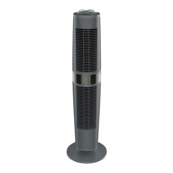
IDENTIFICATION DES COMPOSANTS Instructions pour l'installation de la base : Fig. 1 Fig. 2 1. Assemblez le socle arrière et le socle avant conformément à Fig. 1. 2. Placez le corps principal dans la base assemblée le long de la tige de positionnement, conformément à...
  • Page 14 MODE D’EMPLOI 8H - pas de minuterie - 1H, et ainsi de suite. Les LED s'allument en conséquence. En l'absence de minuterie, l'affichage correspondant Remarque: lors de la première mise sous tension, les bips sonores indique les conditions initiales. Le ventilateur effectuera le compte à signifient que le ventilateur est correctement branché. rebours jusqu'à ce qu'il s'éteigne. Lorsque l'appareil est en veille, seul le mode « MARCHE/ARRÊT » est disponible (bip sonore lors de la mise en marche, bip sonore MODE quand vous appuyez sur les boutons, alerte sonore quand vous Le mode de ventilation initial est «...
  • Page 15 3. Mode nuit INSTRUCTIONS POUR L'ÉCRAN : (a) Haute vitesse : 30 minutes à vitesse normale → 30 minutes de ventilation 1. Écran numérique double 8, 15*14 mm, cathode commune 0,36''. naturelle à vitesse moyenne → Ventilation naturelle à basse vitesse. 2. Dix LED comme indiqué ci-dessous, hors écran numérique. (b). Vitesse moyenne : 30 minutes de ventilation naturelle à vitesse moyenne RC Récepteur →Ventilation naturelle à basse vitesse. Température (c) Basse vitesse : ventilation naturelle à basse vitesse.
  • Page 16 REMARQUE 1. L’anode et la cathode des piles doivent correspondre aux signes Nettoyage de la surface de « + » et de « - » sur la télécommande. 1. Ne laissez pas l'eau et la vapeur s'égoutter sur l'appareil. 2. Si l'unité ne sera pas utilisée pour une durée prolongée, retirez 2.
  • Page 17 Norme de mesure pour dans tous les magasins Jumbo. A l’expiration de la période de garantie, les produits Voir « Norme(s) ou critère(s) pour les tests » lavaleur de service ayce seront repris dans tous les magasins Jumbo pour contrôle. CH-Import & Distribution exklusiv durch: Jumbo-Markt AG Industriestrasse 34, 8305 Dietlikon...
  • Page 18 SCHÉMA TECHNIQUE CARTE DE GARANTIE Prénom Nom de famille Rue/N° Téléphone Code postal Ville Tél. portable : Code-barres (EAN) N° de modèle Garantie (cochez la case) Numéro/date du reçu de vente (Fournissez également une copie du reçu de vente) Acheté dans un magasin Jumbo Quel problème est survenu (veuillez expliquer) (Décrivez le problème ou le dysfonctionnement de votre appareil aussi précisément que possible.
  • Page 19 LISTE DES PIÈCES DE RECHANGE REMARQUE Dénomination Dénomination Base Réflecteur Embout d'où sort le cordon d'alimentation Écran de protection de l'affichage électrique Cordon d'alimentation Bandeau décoratif avant Serre-câble de fixation pour cordon Boîtier avant supérieur d'alimentation Hélice du ventilateur Tige de raccordement Plaque de fixation pour hélice de ventilateur Manchon d'usure Joint d'usure Palier huileux Bague d'usure Capuchon de poignée Boule en acier...
  • Page 20 DESCRIZIONE DEI SIMBOLI AVVERTENZA Conforme alle direttive europee applicabili a questo prodotto. Leggi queste informazioni con cura prima di installare o usare il prodotto. Conserva questo manuale insieme al prodotto per consultazioni future. Simbolo di classe II: questo apparecchio è progettato con un doppio ATTENZIONE materiale isolante.
  • Page 21 Rimuovere l’imballaggio: • Questo dispositivo può essere usato dai bambini dagli 8 anni in • Disimballare i componenti e controllare attentamente che non su e da persone con capacità fisiche, sensoriali o mentali ridotte abbiano subito alcun danno durante il trasporto. In caso di danni o mancanza di esperienza e conoscenza se ricevono supervisione evidenti o di componenti mancanti contattare immediatamente il o istruzioni sull’uso del dispositivo in modo sicuro e capiscono rivenditore.
  • Page 22 IDENTIFICAZIONE DELLE COMPONENTI Istruzioni per il montaggio della base: FIGURA 1 FIGURA 2 1. Assemblare la parte posteriore e anteriore della base nel modo illustrato in FIGURA 1. 2. Inserire il corpo principale nella base assemblata lungo l’asta di posizionamento nel modo illustrato in FIGURA 2. 3.
  • Page 23 temporizzazione nella sequenza 1H- 2H- 4H- 8H- no timer- 1H…. ISTRUZIONI PER L’USO Le spie LED si accendono di conseguenza. Non è attiva la funzione Nota: Al primo inserimento della spina viene emesso un bip che sta timer ed il relativo display si presenta nelle condizioni iniziali. Si ad indicare che il ventilatore è collegato correttamente. attiva il conto alla rovescia fino allo spegnimento del ventilatore.
  • Page 24 3. Modalità Sleep ISTRUZIONI RELATIVE AL DISPLAY: (a) Velocità alta: 30 min. a velocità alta, ventilazione normale→30 min a velocità 1. Display digitale 8 doppio 15*14mm , 0.36inch Common Cathode. media, ventilazione naturale→velocità bassa, ventilazione natural 2. Dieci spie LED come sotto indicate, ad eccezione del display digitale. (b) Velocità media: 30 min a velocità media, ventilazione naturale→velocità Ricevitore RC bassa, ventilazione natural. Temperatura (c) Velocità bassa: velocità bassa, ventilazione naturale. Modalità Sleep Velocità...
  • Page 25 NOTA: 2. Non utilizzare detergenti corrosivi o solventi per pulire l’apparecchio. 1. Anodo e catodo delle batteriedevono essere corrispondenti ai 3. Scollegare l’alimentazione e staccare la spina dalla presa segni “+” e “-” sul telecomando. di corrente prima di pulire l’apparecchio per evitare scosse 2. Durante lunghi tempi di mancato utilizzo, rimuovere le batterie. elettriche.
  • Page 26 Simbolo Valore Unità Jumbo dispone di un eccellente servizio di riparazione, per tutti i prodotti ayce. Qualora si riscontrino difetti relativi ai materiali o alla fabbricazione entro CINQUE ANNI dalla data di acquisto del prodotto, l'utente potrà avvalersi della garanzia, secondo Portata massima d’aria...
  • Page 27 SCHEDA DI GARANZIA SCHEMA TECNICO Nome Cognome Via/Num. Telefono Codice postale Città Telefono cellulare Codice articolo Codice a barre (EAN) Garanzia (contrassegnare con una croce) Numero/data dello scontrino (Allegare una copia dello scontrino Sì di vendita) Acquistato presso un punto vendita Jumbo Problema riscontrato (specificare) (Descrivere il problema nel modo più...
  • Page 28 LISTA DELLE COMPONENTI NOTA DESCRIZIONE DESCRIZIONE Base Protezione lampada Uscita cavo PVC protezione display Cavo di alimentazione Pannello di finitura frontale Staffa di fissaggio del cavo di Rivestimento anteriore alimentazione Vite Girante Biella Piastra di fissaggio girante Manicotto Vite Guarnizione Cuscinetto impregnato in olio Anello di rasamento Copertura con impugnatura Sfera d'acciaio Impugnatura Tappetino di silicone Vite...
  • Page 29 DESCRIPTION OF THE SYMBOLS CAUTION Fire, electric shock, physical injury and material damage hazards. To use the appliance, always follow the instructions for assembly, use and maintenance as well as usage cautions: In accordance with European directives applicable to this product. • Carefully read and retain these instructions. • Before connecting the appliance, make sure that the mains voltage available matches that stipulated on the units’ rating Class II symbol: this appliance is designed with double insulation.
  • Page 30 IDENTIFICATION OF PARTS • This appliance must be placed on a flat and smooth area and the power cord must not pass close to heating appliances. • Always connect this appliance to a 220-240V mains power outlet. • For domestic indoor use only. • Never dip the appliance into water or any other liquid. • Unplug or disconnect the appliance from the mains power supply when not in use or before cleaning it. • Store the appliance in a clean, dry location if you do not plan to use it for a long period. • If the supply cord is damaged, it must be replaced by the manufacturer, its service agent or similarly qualified persons in order to avoid a hazard.
  • Page 31 OPERATING INSTRUCTION Base installation instruction: Note: When plug in first time, the ”BiBi” sound alerts means the fan is correctly connected. When the unit in standby status, only the “ON/OFF” is available.( sound BiBi when plug in, Press buttons with sound Bi, power off with sound. ON/OFF PICTURE1 PICTURE2 Only the “ ” button is available When the unit at standby status. The 1. Lock rear base and front base together according to PICTURE 1. fan under working after pressed this button.
  • Page 32 MODE 4. ECO The initial wind mode is “Normal”, press button to set wind mode and shift as the rule of “Normal”-“Natural” -“Sleeping”-”ECO”- Under this mode, the machine works in Low speed when ambience Normal… The LED lights show accordingly. (No display for NORMAL temperature < 25 ℃ ; in Hi speed when > 29V; in Med speed when 25°C~29°C. Memory function without power off., which can memory the working status mode.) before turn off (not for power off), expect timer & mode function.
  • Page 33 REMOTE CONTROL CLEAN & MAINTAINANCE HOW TO INSTALL BATTERIES If there is too much dust or dirt on the front grid cover and wind wheel of the fan, the performance of air-out would be affected, so we suggest clean the fan once per month at least. 1.
  • Page 34 Additional note service center: Defect products can be returned to every jumbo store during the warranty period. After the warranty period, the ayce products are accepted in any jumbo store, so Measurement standard for the product may be tested in accordance.
  • Page 35 TECHNICAL DRAWING WARRANTY CARD First name Last name Street/NO. Telephone Postal Code City Mobil Item-number Barcode (EAN) Warranty (please mark with a cross) Sales receipt number/Date (please also attach a copy of the sales receipt) Purchased at Jumbo store Which error occurred (please specify) (Please describe the problem or malfunction of your device as accurately as possible.
  • Page 36 SPARE PARTS LIST NOTES DESCRIPTION NO. DESCRIPTION Base Lampshade Buckle line Display PVC Power cord Front trim panel Power cord fixing clamp Anterior shell Screw Wind wheel Connecting rod Wind wheel fixing plate Wear sleeve Screw Wear gasket Oily bearing Wear ring Handle cap Steel ball Handle Silicone pad Screw...

Ce manuel est également adapté pour:

Df-at0900f