Publicité
Les langues disponibles
Les langues disponibles
Liens rapides
Betriebsanleitung
Operating instructions
Notice technique
Istruzioni per l'uso
Instrukcja eksploatacji
Öl-Wassermelder
Version: 12.2019.0
ID: 900.000.0235
Copyright 2019 AFRISO-EURO-INDEX GmbH. Alle Rechte vorbehalten.
Leckage-
erkennungs-
system
Z-65-40-214
Typ: OM 1
Typ: OM 5
Typ: OM 5+1
Lindenstraße 20
74363 Güglingen
Telefon +49 7135 102-0
Service +49 7135 102-211
Telefax +49 7135 102-147
info@afriso.com
www.afriso.com
Publicité

Manuels Connexes pour afriso OM 1

Sommaire des Matières pour afriso OM 1
- Page 1 Operating instructions Notice technique Istruzioni per l’uso Instrukcja eksploatacji Öl-Wassermelder Typ: OM 1 Typ: OM 5 Typ: OM 5+1 Copyright 2019 AFRISO-EURO-INDEX GmbH. Alle Rechte vorbehalten. Lindenstraße 20 74363 Güglingen Leckage- Telefon +49 7135 102-0 erkennungs- Service +49 7135 102-211 system...
- Page 2 Betriebsanleitung Öl-Wassermelder Typ: OM 1 Typ: OM 5 Typ: OM 5+1 Copyright 2019 AFRISO-EURO-INDEX GmbH. Alle Rechte vorbehalten. Leckage- erkennungs- system Z-65-40-214 Version: 12.2019.0 ID: 900.000.0235...
- Page 3 Über diese Betriebsanleitung Über diese Betriebsanleitung Diese Betriebsanleitung beschreibt die Öl-Wassermelder OM 5, OM 5+1 und OM 1 (im Folgenden auch „Produkt“). Diese Betriebsanleitung ist Teil des Produkts. • Sie dürfen das Produkt erst benutzen, wenn Sie die Betriebsanleitung vollständig gelesen und verstanden haben.
- Page 4 Nichtbeachtung einen schweren oder tödlichen Unfall oder Sachschäden zur Folge haben kann. HINWEIS HINWEIS macht auf eine möglicherweise gefährliche Situation aufmerksam, die bei Nichtbeachtung Sachschäden zur Folge haben kann. OM 5 / OM 5+1 / OM 1...
- Page 5 Hinweise, um Unfälle mit Todesfolge, Verlet- zungen und Sachschäden zu vermeiden. Dieses Symbol warnt vor gefährlicher elektrischer Span- nung. Wenn dieses Symbol in einem Warnhinweis gezeigt wird, besteht die Gefahr eines elektrischen Schlags. OM 5 / OM 5+1 / OM 1...
- Page 6 Leckanzeigesystem der Klasse III nach DIN EN 13160-1 und DIN EN 13160-4 als Flüssigkeitssensorsystem in Leckage- oder Überwachungs- räumen, als Sicherheitseinrichtung nach Arbeitsblatt DWA-A 791 oder Leckageerkennungssystem nach Arbeitsblatt DWA-A 779. Eine andere Verwendung ist nicht bestimmungsgemäß und verursacht Gefahren. OM 5 / OM 5+1 / OM 1...
- Page 7 Einsatz des Produkts entstehen können. Den Fachkräften müssen alle geltenden Bestimmungen, Normen und Sicherheitsvorschriften, die bei Arbeiten an und mit dem Produkt beachtet werden müssen, bekannt sein. OM 5 / OM 5+1 / OM 1...
- Page 8 Veränderungen am Produkt Führen Sie ausschließlich solche Arbeiten an und mit dem Produkt durch, die in dieser Betriebsanleitung beschrieben sind. Nehmen Sie keine Verände- rungen vor, die in dieser Betriebsanleitung nicht beschrieben sind. OM 5 / OM 5+1 / OM 1...
- Page 9 Benutzen Sie für den Transport die Originalverpackung. • Lagern Sie das Produkt nur in trockener, sauberer Umgebung. • Stellen Sie sicher, dass das Produkt bei Transport und Lagerung stoßge- schützt ist. Nichtbeachtung dieser Anweisungen kann zu Sachschäden führen. OM 5 / OM 5+1 / OM 1...
- Page 10 Bereichs befestigt. Ab einer Höhe von etwa 4 mm erkennt die Sonde Flüssigkeitsansammlungen. Die Verbindung zum Signalteil erfolgt über eine dreiadrige Leitung. Die Sonde ist nicht dafür bestimmt dauerhaft in Flüssig- keiten eingetaucht zu sein. OM 5 / OM 5+1 / OM 1...
- Page 11 Die Sonde wird in der Höhe des gewünschten Schaltniveaus hängend befes- tigt. Die Verbindung zum Signalteil erfolgt über eine zweiadrige Leitung. Die Art der Schaltfunktion der Schwimmersonde wird mit einem Codierste- cker auf der Leiterplatte des Signalteils festgelegt (Siehe Seite 26). OM 5 / OM 5+1 / OM 1...
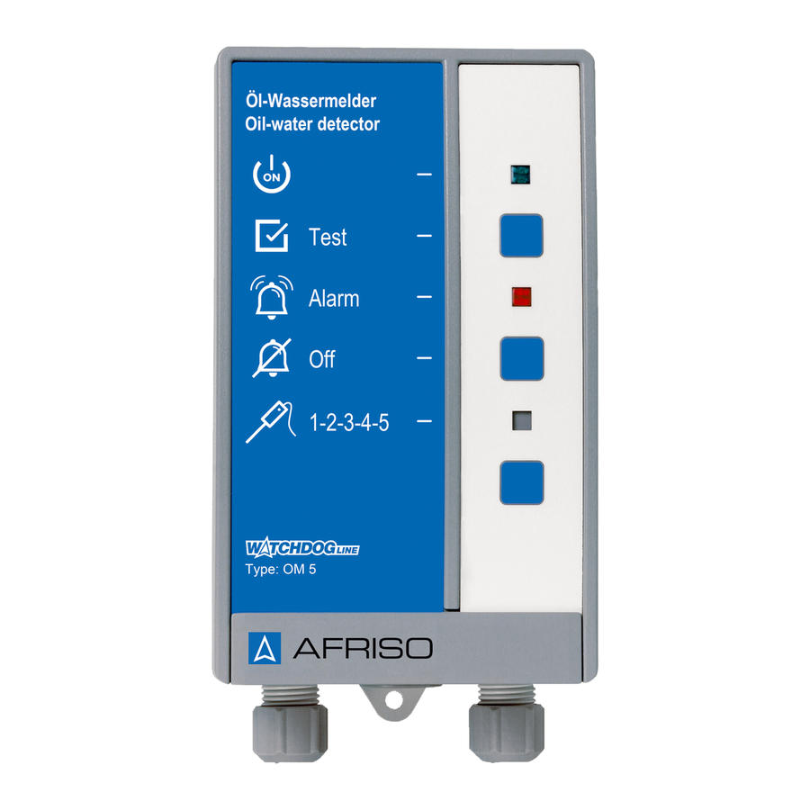
- Page 12 B. Grüne LED C. Test-Taste D. Rote LED E. Quittiertaste (nicht bei OM 1) F. Gelbe LED (nicht bei OM 1) G. Nicht belegt H. Typbezeichnung des Pro- dukts Abbildung 3: Signalteil OM 5 / OM 5+1 / OM 1...
- Page 13 Mit dieser Taste wird der akustische Alarm quit- tiert/abgeschaltet (nicht bei OM 1). Anzeige Bei einem Alarm signalisiert die gelbe LED, welche Sonde Alarm ausgelöst hat (nur bei Verwendung mehrerer Sonden - nicht bei OM 1). OM 5 / OM 5+1 / OM 1...
- Page 14 Produktbeschreibung Abmessungen 65 mm 100 mm 60 mm OM 5 / OM 5+1 / OM 1...
- Page 15 Produktbeschreibung Anwendungsbeispiel A. Auffangwanne C. Kellerraum B. Domschacht Abbildung 4: Standardanwendungen OM 5 / OM 5+1 / OM 1...
- Page 16 • Optische und akustische Alarmgeber • Fernmeldegeräte • Gebäudeleittechnik • Sonstige Zulassungsdokumente, Bescheinigungen, Erklärungen Das Produkt entspricht: • EMV-Richtlinie (2014/30/EU) • Niederspannungsrichtlinie (2014/35/EU) • RoHS-Richtlinie (2011/65/EU) Zulassungen: • Allgemeine bauaufsichtliche Zulassung Z-65.40-214. OM 5 / OM 5+1 / OM 1...
- Page 17 24 x 85 mm Gewicht 0,35 kg Werkstoff Sondenkörper Polypropylen Sondengewicht Messing Beständigkeit Wasser, Öl Anschlusskabel: Ölflex 2 x 0,5 mm² Standardlänge Maximale Länge 50 m (geschirmt) Temperatureinsatzbereich Umgebung -5/50 °C Lagerung -10/60 °C OM 5 / OM 5+1 / OM 1...
- Page 18 Max. 250 V, 2 A, ohmsche Last Elektrische Sicherheit Schutzklasse II (EN 60730) Schutzart IP 30 (EN 60529) Elektromagnetische Verträglichkeit (EMV) (2014/30/EU) Störaussendung EN 61000-6-3 Störfestigkeit EN 61000-6-2 Niederspannungsrichtlinie (2014/35/EU) Angewandte Norm EN 60950-1 OM 5 / OM 5+1 / OM 1...
- Page 19 1. Befestigen Sie die Sonde hängend in der Höhe des gewünschten Schalt- niveaus. Verwenden Sie zur Befestigung eine Kabelschelle oder Kabel- verschraubung als Zugentlastung. 2. Befestigen Sie die Sonde mit der beiliegenden G1-Kabelverschraubung. OM 5 / OM 5+1 / OM 1...
- Page 20 Wenn die Hörbarkeit nicht sichergestellt werden kann, muss ein Zusatz- alarmgerät an geeigneter Stelle im Gebäude angebracht werden (z.B. Zusatzalarmgerät ZAG 01, Hupe KH 1 oder Warnlichthupe von AFRISO). Stellen Sie sicher, dass das Signalteil an eine ebene, feste und trockene Wand in Augenhöhe montiert ist.
- Page 21 Variante A 1. Befestigen Sie die Schraube an der Wand. 2. Hängen Sie das Signalteil ein. 3. Befestigen Sie das Signal- teil an der Wand mit einer Schraube an der unteren Lasche. OM 5 / OM 5+1 / OM 1...
- Page 22 2. Befestigen Sie das Signal- teil an der Wand mit den beiliegenden Schrauben. 3. Schließen Sie das Signal- teil wie in Kapitel "Elektri- scher Anschluss" beschrieben an. 4. Schließen Sie das Signal- teil. OM 5 / OM 5+1 / OM 1...
- Page 23 Gummitülle verwendet wer- den. Bei einer losen Kabelleitung muss die mittlere Gummitülle durch eine Kabelverschrau- bung M20 ersetzt werden. - M16 = 4 - 8,8 mm - M20 = 8 - 12,5 mm OM 5 / OM 5+1 / OM 1...
- Page 24 Installieren Sie keine Netzstecker oder Schalter in der Spannungsversor- gung für das Produkt. • Schalten Sie das Produkt nur über die bauseitige Netzsicherung ein und aus. Nichtbeachtung dieser Anweisungen kann zu Sachschäden führen. OM 5 / OM 5+1 / OM 1...
- Page 25 1. Führen Sie beim OM 5 und OM 5+1 das Netzkabel durch die linke Kabelverschraubung in das Signalteil ein. 2. Führen Sie beim OM 1 das Netzkabel durch die rechte Kabelver- schraubung in das Signalteil ein. 3. Klemmen Sie die Phase an die Klemme L1 und den Neutralleiter an die Klemme N.
- Page 26 8. Schwimmersonde F1 Netzsicherung J1 Codierstecker Abbildung 7: Elektrischer Anschluss OM 5+1 1. Spannungsversorgung F1 2. Weiß 3. Braun 4. Grün 5. Beliebige externe Geräte 6. Netzspannung Abbildung 8: Elektrischer Anschluss OM 1 OM 5 / OM 5+1 / OM 1...
- Page 27 Montage 5.5.2 Sonden anschließen Das Produkt OM 1 wird mit einer fest angeschlossenen optoelektroni- schen Sonde geliefert. Das Sondenkabel darf nicht gekürzt oder verlän- gert werden. OM 5 und OM 5+1: Zur Verlängerung der Sondenkabel müssen Kabel mit 3 x 1 mm² verwen- det werden.
- Page 28 Auswirkungen auf elektrische Anlagen haben und zur Zerstörung des Schalt- kontakts führen. • Beschalten Sie induktive Verbraucher mit handelsüblichen RC-Kombinatio- nen z. B. 0,1 µF/100 Ohm. Nichtbeachtung dieser Anweisungen kann zu Sachschäden führen. OM 5 / OM 5+1 / OM 1...
- Page 29 • Die rote LED leuchtet und der akustische Alarm ertönt. • Die gelbe LED zeigt durch 1 bis 5 Blinkimpulse die Nummer der Sonde, die den Alarm ausgelöst hat (nicht beim OM 1). 2. Entfernen Sie den Gegenstand oder nehmen Sie die Sonde aus der Flüs- sigkeit.
- Page 30 Inbetriebnahme Am Signalteil 1. Drücken Sie die Prüftaste am Signalteil • Die rote LED leuchtet und der akustische Alarm ertönt. Drücken Sie die Taste "Quittieren", um den Funktionstest am Signalteil zu beenden. OM 5 / OM 5+1 / OM 1...
- Page 31 Betrieb Betrieb Das Produkt überwacht Bereiche und meldet Flüssigkeitsansammlungen. Wenn eine oder mehrere der optoelektronischen Sonden in Flüssigkeit taucht, meldet das Produkt einen Alarm. Der OM 5+1 überwacht zusätzlich einen Minimal- oder Maximalfüllstand. Wenn die Schwimmersonde für den Minimalfüllstand verwendet wird, gibt das Signalteil Alarm, sobald der Flüssigkeitspegel unter den eingestellten Grenzwert absinkt.
- Page 32 Sender und Empfänger der Lichtschranke gebildet haben. 4. Führen Sie eine Funktionsprüfung durch. Schwimmersonde prüfen: Die Schwimmersonde bedarf nach einem Alarmfall keiner besonderen Prü- fung. Führen Sie eine Funktionsprüfung durch. Siehe “Funktionsprüfung durchführen” auf Seite 28. OM 5 / OM 5+1 / OM 1...
- Page 33 Wartung Wartung Wartungsintervalle Zeitpunkt Tätigkeit 1 x jährlich und Führen Sie eine Sichtprüfung der Sonden durch. Siehe "Nach einem Alarmfall". nach Alarmfall Reinigen Sie verschmutze Teile und tauschen Sie beschädigte Teile aus. Führen Sie eine Funktionsprüfung durch. Siehe “Funktionsprüfung durchführen” auf Seite 28. Wartungstätigkeiten GEFAHR ELEKTRISCHER SCHLAG DURCH SPANNUNGSFÜHRENDE TEILE...
- Page 34 Sonde in Flüs- ren oder gegen Licht sigkeit ist oder Schwim- abschirmen mersonde reagieren Schwimmer der Schwimmersonde müsste Schwimmersonde nicht anders platzieren oder frei beweglich Schwimmer gangbar machen Sonde defekt Sonde tauschen OM 5 / OM 5+1 / OM 1...
- Page 35 Kurzschluss in der Sonde prüfen ernd, auch wenn Sonde Sonde nicht in Flüssigkeit ist Leitungsunterbre- Sondenkabel prüfen chung in der Sonde Drücken der Prüftaste Signalteil defekt Signalteil tauschen bleibt ohne Wirkung Sonstige Störungen Bitte wenden Sie sich an die AFRISO-Service Hotline...
- Page 36 Vor einer Rücksendung Ihres Produkts müssen Sie sich mit uns in Verbin- dung setzen. Gewährleistung Informationen zur Gewährleistung finden Sie in unseren Allgemeinen Geschäftsbedingungen im Internet unter www.afriso.com oder in Ihrem Kauf- vertrag. OM 5 / OM 5+1 / OM 1...
- Page 37 Abbildung Signalteil OM 5 44502 Signalteil OM 5, 24 V 44486 Signalteil OM 5+1 mit 1 optoelektroni- 44517 schen Sonde und 1 Schwimmersonde Signalteil OM 1 mit 1 optoelektronischen 44501 Sonde Ersatzteile und Zubehör Artikelbezeichnung Art.-Nr. Abbildung Optoelektronische Sonde 44503...
- Page 38 Anhang Anhang 14.1 Allgemeine bauaufsichtliche Zulassung (Deutschland) OM 5 / OM 5+1 / OM 1...
- Page 39 Anhang...
- Page 40 Anhang OM 5 / OM 5+1 / OM 1...
- Page 41 Anhang...
- Page 42 Anhang OM 5 / OM 5+1 / OM 1...
- Page 43 Anhang...
- Page 44 Anhang OM 5 / OM 5+1 / OM 1...
- Page 45 Anhang 14.2 Zulassungsunterlagen (Belgien)
- Page 46 Anhang 14.3 EU-Konformitätserklärung OM 5 / OM 5+1 / OM 1...
- Page 47 Operating instructions Oil/water alarm unit Type: OM 1 Type: OM 5 Type: OM 5+1 Copyright 2019 AFRISO-EURO-INDEX GmbH. All rights reserved. Lindenstraße 20 74363 Güglingen Telephone +49 7135 102-0 Leakage de- tection sy- Service +49 7135 102-211 stem Telefax +49 7135 102-147 Z-65-40-214 info@afriso.com...
- Page 48 About these operating instructions About these operating instructions These operating instructions describe the oil/water alarm unit OM 5, OM 5+1 and OM 1 (also referred to as "product" in these operating instructions). These operating instructions are part of the product. •...
- Page 49 This symbol alerts to hazardous electrical voltage. If this symbol is used in a safety message, there is a hazard of electric shock. OM 5 / OM 5+1 / OM 1...
- Page 50 DWA-A 791 or leak detection system as per worksheet DWA-A 779. Any use other than the application explicitly permitted in these operating instructions is not permitted and causes hazards. OM 5 / OM 5+1 / OM 1...
- Page 51 All persons working on and with the product must be fully familiar with all directives, standards and safety regulations that must be observed for per- forming such work. OM 5 / OM 5+1 / OM 1...
- Page 52 Only perform work on and with the product which is explicitly described in these operating instructions. Do not make any modifications to the product which are not described in these operating instructions. OM 5 / OM 5+1 / OM 1...
- Page 53 Store the product in a clean and dry environment. • Verify that the product is protected against shocks and impact during trans- port and storage. Failure to follow these instructions can result in equipment damage. OM 5 / OM 5+1 / OM 1...
- Page 54 The probe detects accumulations of liquids at a height of approximately 4 mm. A three-wire cable is used for connection to the control unit. The probe is not intended to be permanently submerged in liquid. OM 5 / OM 5+1 / OM 1...
- Page 55 A two-wire cable is used for connection to the control unit. The type of switching function of the floating probe is determined by means of a coding plug on the PCB of the control unit (see Page 25). OM 5 / OM 5+1 / OM 1...
- Page 56 C. Test key D. Red LED E. Acknowledge button (not with OM 1) F. Yellow LED (not with OM 1) G. Not assigned H. Type designation of the product Fig. 3: Control unit OM 5 / OM 5+1 / OM 1...
- Page 57 This key allows you to acknowledge and mute the audible alarm (not with OM 1). Indicator The yellow LED identifies the probe which has trig- gered the alarm (only if multiple probes are used - not with OM 1). OM 5 / OM 5+1 / OM 1...
- Page 58 Product description Dimensions 65 mm 100 mm 60 mm OM 5 / OM 5+1 / OM 1...
- Page 59 Product description Application example A. Drip pan C. Basement room B. Manhole Fig. 4: Standard applications OM 5 / OM 5+1 / OM 1...
- Page 60 Approvals, conformities, certifications The product complies with: • EMC Directive (2014/30/EU) • Low Voltage Directive (2014/35/EU) • RoHS Directive (2011/65/EU) Approvals: • Technical Approval of the German Institute for Civil Engineering (DIBt) Z-65.40-214. OM 5 / OM 5+1 / OM 1...
- Page 61 Material probe body Polypropylene Probe weight Brass Resistance Water, oil Connection cable: Ölflex 2 x 0.5 mm² Standard length Maximum length 50 m (shielded) Operating temperature range Ambient -5/50 °C Storage -10/60 °C OM 5 / OM 5+1 / OM 1...
- Page 62 Protection class II (EN 60730) Degree of protection IP 30 (EN 60529) Electromagnetic compatibility (EMC) (2014/30/EU) Emitted interference EN 61000-6-3 Noise immunity EN 61000-6-2 Low Voltage Directive (2014/35/EU) Applied standard EN 60950-1 OM 5 / OM 5+1 / OM 1...
- Page 63 1. Mount the probe in such a way that it is suspended at the height/level of the required switching point. Use a cable clamp or the cable gland to fas- ten the probe and provide strain relief. 2. Fasten the probe with the enclosed cable G1 gland. OM 5 / OM 5+1 / OM 1...
- Page 64 (for example, additional alarm unit ZAG 01, horn KH 1 or combined alarm light and horn from AFRISO). Verify that the control unit is mounted to an even, rigid and dry wall at eye level.
- Page 65 A or B. Use the housing as a drilling template. Mounting type A 1. Mount the screw to the wall. 2. Fit the control unit. 3. Fasten the control unit by screwing the bottom lug to the wall. OM 5 / OM 5+1 / OM 1...
- Page 66 Ø 5 mm into the base. 2. Mount the control unit to the wall with the enclosed screws. 3. Connect the control unit as described in chapter "Electrical connection". 4. Close the control unit. OM 5 / OM 5+1 / OM 1...
- Page 67 In the case of a cable that is not permanently installed, you must replace the centre rubber piece by an M20 cable gland. - M16 = 4 - 8.8 mm - M20 = 8 - 12.5 mm OM 5 / OM 5+1 / OM 1...
- Page 68 Do not install mains plugs or switches in the supply line to the product. • Only power on/power off the product via the on-site mains fuse. Failure to follow these instructions can result in equipment damage. OM 5 / OM 5+1 / OM 1...
- Page 69 1. In the case of OM 5 and OM 5+1, route the mains cable through the cable gland at the left into the control unit. 2. In the case of OM 1, route the mains cable through the cable gland at the right into the control unit.
- Page 70 J1 coding plug Fig. 7: Electrical connection OM 5+1 1. Supply voltage F1 2. White 3. Brown 4. Green 5. Any external equipment 6. Mains voltage Fig. 8: Electrical connection OM 1 OM 5 / OM 5+1 / OM 1...
- Page 71 Mounting 5.5.2 Connecting the probes The product OM 1 is shipped with a permanently connected photoelectric probe. Do not extend or shorten the probe cable. OM 5 and OM 5+1: Use only 3 x 1 mm² cables to extend the probe cables. Use shielded cables for lengths of more than 15 m.
- Page 72 Mounting 3. If the floating probe is not connected: - If the coding plug J1 is plugged in, leave the terminals "IN" and "GND" open. - If the coding plug J1 is not plugged in, jumper the terminals "IN" and "GND".
- Page 73 • The red LED lights up and the audible alarm is activated. • The yellow LED identifies the number of the probe which has triggered the alarm by means of 1 to 5 flash pulses (not OM 1). 2. Remove the probe from the liquid or remove the object.
- Page 74 Commissioning At the control unit 1. Press the Test button at the control unit. • The red LED lights up and the audible alarm is activated. Press the "Acknowledge" key to terminate the function test at the con- trol unit.
- Page 75 The number of flash pulses of the yellow LED identifies the probe (1 to 6) which has trig- gered the alarm. The flash pulses are repeated at intervals of approximately three seconds. OM 5 / OM 5+1 / OM 1...
- Page 76 Operation • Example: Probe 2 triggers an alarm. The yellow LED flashes twice. After approxi- mately three seconds, the yellow LED flashes twice again. This is repeated until you have acknowledged the alarm. Acknowledging an alarm You can mute the audible alarm by pressing the "Acknowledge" key. Press the key again to switch on the audible alarm again.
- Page 77 3. Insert a new mains fuse F1, see Page 16. 4. Refit the transparent cover. 5. Connect the flat cable to the connector. 6. Close the control unit, see 1 above. 7. Apply mains voltage. OM 5 / OM 5+1 / OM 1...
- Page 78 Troubleshooting Troubleshooting The product is safety equipment. Any malfunctions that cannot be removed by means of the measures described in this chapter may only be repaired by the manufacturer. Problem Possible reason Repair Green LED is not on No mains voltage Apply mains voltage Mains fuse defective Replace the mains fuse...
- Page 79 Line interruption in the Check the probe cable probe Pressing the Test but- Control unit defective Replace the control unit ton has no effect Other malfunctions Contact the AFRISO service hotline OM 5 / OM 5+1 / OM 1...
- Page 80 2. Dismount the product (see chapter "Mounting the control unit", reverse sequence of steps). 3. Dispose of the product. Returning the device Get in touch with us before returning your product. Warranty See our terms and conditions at www.afriso.com or your purchase contract for information on warranty.
- Page 81 Mains fuse F1 (M 32 mA) 941571 0032 additional alarm unit ZAG 01 40633 Warning light with rotating reflector 61015 Horn KH 1 61011 Combined alarm light and horn 61020 Horn HPW 2 61012 OM 5 / OM 5+1 / OM 1...
- Page 82 Notice technique Détecteur d'huile/d'eau Type : OM 1 Type : OM 5 Type : OM 5+1 Copyright 2019 AFRISO-EURO-INDEX GmbH. Tous droits réservés. Lindenstraße 20 74363 Güglingen Téléphone +49 7135 102-0 détection de Service clientèle +49 7135 102-211 fuite Téléfax +49 7135 102-147 Z-65-40-214 info@afriso.com...
- Page 83 La présente notice technique La présente notice technique Cette notice technique contient la description du détecteur d'huile/d'eau OM 5, OM 5+1 et OM 1 (dénommé ci-après "produit"). Cette notice tech- nique fait partie du produit. • Utilisez le produit seulement après que vous aurez lu et compris intégra- lement la notice technique.
- Page 84 Ceci est le pictogramme général de mise en garde. Il signale un risque de blessure et de dommage matériel. Respectez toutes les consignes de sécurité afin d'éviter des accidents mortels, des blessures ou des dommages matériels. OM 5 / OM 5+1 / OM 1...
- Page 85 Informations sur la sécurité Ce pictogramme avertit d'une tension électrique dange- reuse. Si ce pictogramme s'affiche dans une consigne de sécurité, il y a un risque de choc électrique. OM 5 / OM 5+1 / OM 1...
- Page 86 ; comme dispositif de sécurité selon feuille de travail DWA-A 791 ou comme détecteur de fuite selon feuille de travail DWA-A 779. Toute autre utilisation n'est pas conforme et cause des risques. OM 5 / OM 5+1 / OM 1...
- Page 87 être causés par l'utilisation du produit. Tous les règlements, normes et consignes de sécurité en vigueur sur le lieu d'installation doivent être connus du personnel qualifié travaillant sur le pro- duit et avec celui-ci. OM 5 / OM 5+1 / OM 1...
- Page 88 Modification du produit En travaillant sur le produit et avec celui-ci, effectuez exclusivement les opé- rations décrites dans cette notice technique. N'effectuez pas de modifica- tions non décrites dans cette notice technique. OM 5 / OM 5+1 / OM 1...
- Page 89 Stockez le produit dans un lieu sec et propre. • Assurez-vous que le produit est à l'abri des chocs pendant le transport et le stockage. La non-observation de ces instructions peut causer des dommages maté- riels. OM 5 / OM 5+1 / OM 1...
- Page 90 OM 5+1 : 1 à 5 sondes optoélectroniques, 1 sonde à flotteur (une sonde fournie par commande) • OM 1 : 1 sonde optoélectronique (raccordement fixe) Le produit surveille la présence éventuelle des liquides accumulés à des points (cinq max.) distants les uns des autres. Une ou plusieurs sondes optoélectroniques plongées dans le liquide, l'unité...
- Page 91 à deux fils. Le type de la fonction de commutation de la sonde à flotteur est déterminé par l'intermédiaire d'un connecteur de codage sur la platine de l'unité de commande (voir Page 27). OM 5 / OM 5+1 / OM 1...
- Page 92 D. LED rouge E. Touche d'acquittement (pas disponible avec OM 1) F. LED jaune (pas disponible avec OM 1) G. Sans fonction H. Désignation de type de produit Figure 3: Unité de commande OM 5 / OM 5+1 / OM 1...
- Page 93 Cette touche permet d'acquitter et de couper l'alarme sonore (pas disponible avec OM 1). Affichage La LED jaune indique la sonde ayant déclenché l'alarme (seul si plusieurs sondes sont utilisées ; pas disponible avec OM 1). OM 5 / OM 5+1 / OM 1...
- Page 94 Description du produit Dimensions 65 mm 100 mm 60 mm OM 5 / OM 5+1 / OM 1...
- Page 95 Description du produit Exemple d'application A. Bac collecteur C. Cave B. Trou d'homme Figure 4: Applications standard OM 5 / OM 5+1 / OM 1...
- Page 96 Agréments, certificats, déclarations Le produit est conforme à : • Directive CEM (2014/30/UE) • Directive basse tension (2014/35/UE) • Directive RoHS (2011/65/UE) Certifications : • Agrément du Deutsches Institut für Bautechnik DiBT Z-65.40-214. OM 5 / OM 5+1 / OM 1...
- Page 97 Poids de la sonde Laiton Résistance Eau, huile Câble de branchement : Ölflex 2 x 0,5 mm² Longueur standard Longueur maximale 50 m (blindé) Plage de température Ambiante -5/50 °C Stockage -10/60 °C OM 5 / OM 5+1 / OM 1...
- Page 98 M 32 mA Pouvoir de coupure relais sortie Max. 250 V, 2 A, charge résistive Sécurité électrique Classe de protection II (EN 60730) Degré de protection IP 30 (EN 60529) Compatibilité électromagnétique (CEM) (2014/30/UE) OM 5 / OM 5+1 / OM 1...
- Page 99 Description du produit Paramètre Valeur Émission EN 61000-6-3 Immunité EN 61000-6-2 Directive basse tension (2014/35/UE) Norme appliquée EN 60950-1 OM 5 / OM 5+1 / OM 1...
- Page 100 1. Suspendez la sonde à la hauteur du niveau de commutation. Servez-vous d'un collier ou du presse-étoupe afin d'effectuer une décharge de traction. 2. Fixez la sonde avec le presse-étoupe G1 fourni. OM 5 / OM 5+1 / OM 1...
- Page 101 à l'extérieur. Figure 5: Unité de commande avec cadre de montage pour installation dans un pan- neau de commande ; à droite : découpe du tableau de commande OM 5 / OM 5+1 / OM 1...
- Page 102 Type de fixation A 1. Introduisez la vis dans le mur. 2. Accrochez l'unité de com- mande. 3. Fixez l'unité de com- mande sur la paroi en vis- sant la vis dans la patte inférieure. OM 5 / OM 5+1 / OM 1...
- Page 103 2. Fixez l'unité de com- mande sur le mur avec les vis fournies. 3. Raccordez l'unité de com- mande comme décrit dans le chapitre "Bran- chement électrique". 4. Fermez l'unité de com- mande. OM 5 / OM 5+1 / OM 1...
- Page 104 M20. - M16 = 4 - 8,8 mm - M20 = 8 - 12,5 mm OM 5 / OM 5+1 / OM 1...
- Page 105 N'installez pas des fiches secteur et des commutateurs dans l'alimentation du produit. • Allumez et éteindrez le produit uniquement par l'intermédiaire du fusible sec- teur. La non-observation de ces instructions peut causer des dommages maté- riels. OM 5 / OM 5+1 / OM 1...
- Page 106 1. En cas d'OM 5 et OM 5+1, faites passer le câble secteur par le presse-étoupe à gauche dans l'unité de commande. 2. En cas d'OM 1, faites passer le câble secteur par le presse-étoupe à droite dans l'unité de commande.
- Page 107 8. Sonde à flotteur Fusible de secteur F1 J1 connecteur de codage Figure 7: Branchement électrique OM 5+1 1. Alimentation F1 2. Blanc 3. Brun 4. Vert 5. Équipements supplémen- taires 6. Tension secteur Figure 8: Branchement électrique OM 1...
- Page 108 Montage 5.5.2 Branchement des sondes Le produit OM 1 est livré avec la sonde optoélectronique branchée en permanence. Ne pas raccourcir ou prolonger le câble. OM 5 et OM 5+1 : Pour rallonger les câbles de la sonde, utilisez des câbles 3 x 1 mm². Si la longueur dépasse 15 m, utilisez un câble blindé.
- Page 109 Montage 3. Si la sonde à flotteur n'est pas branchée : - Si le connecteur de codage J1 est connecté, laissez ouvert les bornes "IN" et "GND". - Si le connecteur de codage J1 n'est pas connecté, utilisez un cavalier sur les bornes "IN"...
- Page 110 • La LED rouge est allumée et l'alarme sonore retentit. • La LED jaune indique par 1 à 5 clignotements le numéro de la sonde ayant déclenché l'alarme (pas disponible en cas d'OM 1). 2. Retirez l'objet ou retirez la sonde du liquide.
- Page 111 Mise en service Sur l'unité de commande 1. Appuyez sur la touche de test de l'unité de commande. • La LED rouge est allumée et l'alarme sonore retentit. Appuyez sur la touche "Acquittement" afin de terminer le test de fonc- tionnement sur l'unité...
- Page 112 - Si la sonde à flotteur est utilisée pour détecter un niveau maximal, le produit donne l'alarme quand la sonde à flotteur est immergée dans le liquide. En cas d'une alarme de niveau, la LED rouge clignote et l'alarme sonore retentit. OM 5 / OM 5+1 / OM 1...
- Page 113 Service Si les alarmes de fuite et de niveau se produisent simultanément, la LED rouge est allumée en permanence et l'alarme sonore retentit. Le nombre d'impulsions de clignotement du LED jaune permet de savoir laquelle des sondes (1 à 6) a déclenché l'alarme. Les clignotements ont lieu toutes les trois secondes.
- Page 114 3. Remplacez le fusible de secteur F1, voir Page 17. 4. Remontez le capot de protection transparent. 5. Branchez le câble plat au connecteur. 6. Fermez l'unité de commande, voir aussi point 1. 7. Allumez la tension secteur. OM 5 / OM 5+1 / OM 1...
- Page 115 Suppression des dérangements Suppression des dérangements Le produit est un dispositif de sécurité. Les dérangements ne figurant pas dans les mesures décrites dans ce cha- pitre doivent être éliminés uniquement par le fabricant. Problème Cause possible Action corrective La LED verte ne La tension secteur est Établir la tension sec- s'allume pas...
- Page 116 Vérifier le câble de du liquide la sonde sonde L'actionnement de la Unité de commande Remplacer l'unité de touche de test reste défectueuse commande sans effet Autre dérangement Veuillez contacter l'AFRISO Service Hot- line OM 5 / OM 5+1 / OM 1...
- Page 117 3. Éliminez le produit. Retour Avant de retourner le produit, il faut que vous preniez contact avec nous. Garantie Les informations sur la garantie figurent dans nos "Conditions générales de vente" sur le site www.afriso.com ou dans votre contrat d'achat.
- Page 118 Unité de commande OM 5, 24 V 44486 Unité de commande OM 5+1 avec 1 sonde 44517 optoélectronique et 1 sonde à flotteur Unité de commande OM 1 avec 1 sonde 44501 optoélectronique Pièces détachées et accessoires Désignation de l'article Référence Figure...
- Page 119 Istruzioni per l’uso Detettore perdite olio-acqua Tipo: OM 1 Tipo: OM 5 Tipo: OM 5+1 Copyright 2019 AFRISO-EURO-INDEX GmbH. Tutti i diritti sono riservati. Lindenstraße 20 74363 Güglingen Telefono +49 7135 102-0 Rilevatore di perdite Servizio di assistenza +49 7135 102-211...
- Page 120 Su queste Istruzioni per l'uso Su queste Istruzioni per l'uso Queste Istruzioni per l'uso descrivono i detettori di perdite olio-acqua OM 5, OM 5+1 e OM 1 (nel proseguio anche il "prodotto"). Le presenti Istruzioni per l’uso costituiscono parte del prodotto. •...
- Page 121 Questo è il simbolo di avvertimento generico. Avverte del pericolo di lesioni fisiche o danni materiali. Rispettate sem- pre le indicazioni corredate del simbolo di avvertimento per evitare incidenti con conseguenze anche fatali, lesioni fisi- che e danni materiali. OM 5 / OM 5+1 / OM 1...
- Page 122 Informazioni sulla sicurezza Questo simbolo segnala tensione elettrica pericolosa. Quando questo simbolo è riportato all'interno un avverti- mento segnala pericolo da scossa elettrica. OM 5 / OM 5+1 / OM 1...
- Page 123 DWA-A 791 come sistema di rilevamento perdite secondo il foglio di lavoro DWA-A 779. Ogni altro utilizzo è da considerarsi non conforme e causa pericoli. OM 5 / OM 5+1 / OM 1...
- Page 124 Il personale specializzato deve essere a conoscenza di tutte le disposizioni, norme e prescrizioni di sicurezza vigenti che si riferiscono ai lavori con e al prodotto. OM 5 / OM 5+1 / OM 1...
- Page 125 Modifiche del prodotto Eseguite esclusivamente i lavori con e al prodotto descritti nelle Istruzioni per l'uso. Non apportate modifiche al prodotto che non sono descritte nelle Istru- zioni per l'uso. OM 5 / OM 5+1 / OM 1...
- Page 126 Immagazzinate il prodotto solo in ambiente asciutto e pulito. • Assicurare che il prodotto sia prodotto contro urti durante il trasporto e il magazzinaggio. La mancata osservanza di queste indicazioni può causare danni materiali. OM 5 / OM 5+1 / OM 1...
- Page 127 La sonda riconosce accumuli di liquido a partire da un'altezza di 4 mm ca. Collegamento all'unità di segnale mediante cavo a tre fili. La sonda non è concepita per restare immersa in liquido per un periodo prolungato. OM 5 / OM 5+1 / OM 1...
- Page 128 Il tipo di funzione di commutazione della sonda galleggiante si può determi- nare con un interruttore a codice sul circuito stampato dell'unità di segnale (si veda Pagina 26). OM 5 / OM 5+1 / OM 1...
- Page 129 D. LED rosso E. Tasto di tacitazione allarme (non in OM 1) F. LED giallo (non in OM 1) G. non assegnato H. Nome di tipo del prodotto Figura 3: Unità di segnale OM 5 / OM 5+1 / OM 1...
- Page 130 (non per OM 1). Visualizzazione In caso di allarme, il LED giallo indica quale sonda ha fatto scattare l'allarme (solo in caso di utilizzo di più di una sonda - non per OM 1). OM 5 / OM 5+1 / OM 1...
- Page 131 Descrizione del prodotto Dimensioni 65 mm 100 mm 60 mm OM 5 / OM 5+1 / OM 1...
- Page 132 Descrizione del prodotto Esempio applicativo A. Vasca di raccolta C. Cantina B. Passo d'uomo Figura 4: Applicazioni standard OM 5 / OM 5+1 / OM 1...
- Page 133 Documenti di omologazione, certificati, dichiarazioni Il prodotto risponde a • la Direttiva Compatibilità Elettromagnetica (2014/30/UE) • la Direttiva Bassa Tensione (2014/35/UE) • la Direttiva RoHS (2011/65/UE) Omologazioni • Autorizzazione generale dell’ispettorato edile tedesco Z-65.40-214 OM 5 / OM 5+1 / OM 1...
- Page 134 Polipropilene Peso sonda Ottone Resistente a acqua, olio Cavo di collegamento Ölflex 2 x 0,5 mm² Lunghezza standard Lunghezza massima 50 m (schermati) Campo di temperatura Ambiente -5/50 °C Stoccaggio -10/60 °C OM 5 / OM 5+1 / OM 1...
- Page 135 Classe di protezione II (EN 60730) Grado di protezione IP 30 (EN 60529) Compatibilità elettromagnetica (CEM) (2014/30/UE) Emissioni EN 61000-6-3 Immunità a interferenze EN 61000-6-2 la Direttiva Bassa Tensione (2014/35/UE) Normativa adottata EN 60950-1 OM 5 / OM 5+1 / OM 1...
- Page 136 1. Installare la sonda a galleggiante in posizione appesa all'altezza di com- mutazione desiderata. Per fissare la sonda usare una boccola o un'avvi- tamento per limitare la trazione. 2. Fissare la sonda con l'avvitamento cavo G1 a corredo. OM 5 / OM 5+1 / OM 1...
- Page 137 Se l'udibilità non è assicurata è necessario installare un dispositivo d'allarme aggiuntivo in una posizione adatta all'interno dell'edificio (ad es., allarme aggiuntivo ZAG 01, clacson KH 1 o avvisatore visivo AFRISO). Assicurare che l'unità di segnale sia montata su una parete piana, stabile e asciutta, all’altezza degli occhi.
- Page 138 A o B) Utilizzare l'alloggiamento come dima di foratura. Variante A 1. Fissate la vite al muro. 2. Appendere l'unità di segnale. 3. Fissare al muro l'unità di segnale con una vite nella linguetta inferiore. OM 5 / OM 5+1 / OM 1...
- Page 139 Ø 5 mm nella parte inferiore. 2. Montare l'unità di segnale a parete con le viti a cor- redo. 3. Allacciare l'unità di segnale come descritto al Capitolo "Allacciamento elettrico". 4. Chiudere l’unità di segnale. OM 5 / OM 5+1 / OM 1...
- Page 140 Con cavo non fisso, il tappo di gomma centrale va sostituito con un avvitamento cavi M20. - M16 = 4 - 8,8 mm - M20 = 8 - 12,5 mm OM 5 / OM 5+1 / OM 1...
- Page 141 Non installare spine di rete o interruttori lungo l'allacciamento fisso del pro- dotto. • Inserire il prodotto solo mediante la protezione di rete a cura del commit- tente. La mancata osservanza di queste indicazioni può causare danni materiali. OM 5 / OM 5+1 / OM 1...
- Page 142 1. Per OM 5 e OM 5+1, introdurre il cavo di allacciamento nell’unità di segnale facendolo passare attraverso il passacavo a sinistra. 2. Per l'OM 1, introdurre il cavo di allacciamento nell'unità di segnale facendolo passare attraverso il passacavo a destra.
- Page 143 Interruttore a codice J1 Figura 7: Allacciamento elettrico OM 5-1 1. Alimentazione elettrica F1 2. Bianco 3. Marrone 4. Verde 5. Dispositivi esterni vari 6. Tensione di rete Figura 8: Allacciamento elettrico OM 1 OM 5 / OM 5+1 / OM 1...
- Page 144 Montaggio 5.5.2 Collegamento sonde Il prodotto OM 1 viene fornito con sonda fotoelettrica connessa stabil- mente. Non è permesso accorciare o allungare il cavo della sonda. OM 5 e OM 5+1: Per prolungare i cavi delle sonde, utilizzare cavi con 3 x 1 mm². A partire da una lunghezza di 15 m è...
- Page 145 • Collegare le utenze induttive con le comuni combinazioni RC, ad es. 0,1 µF/100 Ohm. La mancata osservanza di queste indicazioni può causare danni materiali. OM 5 / OM 5+1 / OM 1...
- Page 146 • Il LED rosso si accende e si sente l’allarme acustico. • Il LED giallo indica mediante il numero degli impulsi luminosi (da 1 a 5) quale sonda ha fatto scattare l'allarme (non per OM 1). 2. Estrarre la sonda dal liquido, rispettivamente rimuovere l'oggetto dalla barriera fotoelettrica.
- Page 147 1. Premere il pulsante di prova sull'unità di segnale. • Il LED rosso si accende e si sente l’allarme acustico. Premere il pulsante "Conferma" per concludere il test di funzionamento dell'unità di segnale. OM 5 / OM 5+1 / OM 1...
- Page 148 Operazione Operazione Il prodotto sorveglia spazi e segnala accumuli di liquido. Quando una o più sonde fotoelettriche vengono a contatto con liquido, l'allarme scatta. OM 5+1 inoltre sorveglia anche il raggiungimento di un livello minimo o mas- simo. Quando viene usata la sonda galleggiante per monitorare il livello minimo, l'unità...
- Page 149 4. Eseguire una prova di funzionamento. Controllare la sonda galleggiante: La sonda galleggiante non richiede controlli particolari dopo un allarme. Ese- guire una prova di funzionamento. Vedere “Prova di funzionamento” a pagina 28. OM 5 / OM 5+1 / OM 1...
- Page 150 Manutenzione Manutenzione Intervalli di manutenzione Data Attività 1 x all’anno Eseguire una prova a vista delle sonde. si veda "Dopo un allarme". Dopo ogni allarme Pulire le parti sporche e sostituire le parti danneg- giate. Eseguire una prova di funzionamento. Vedere “Prova di funzionamento”...
- Page 151 Galleggiante della Posizionare diversa- emerge/viene immersa sonda a galleggiante mente la sonda a gal- non è libero di muoversi leggiante o liberare il galleggiante Sonda difettosa Sostituire la sonda OM 5 / OM 5+1 / OM 1...
- Page 152 è Connessione interrotta Controllare il cavo della immersa in liquido nella sonda sonda Il pulsante di prova non Unità di segnale difet- Sostituire l'unità di funziona (non ha tosa segnale effetto) Altri guasti Rivolgetevi alla hotline di assistenza AFRISO...
- Page 153 Prima di rispedire il prodotto, mettetevi in contatto con noi. Garanzia Le informazioni sulla garanzia sono riportate nelle condizioni di contratto generali in internet sul sito www.afriso.com o nel vostro contratto d'acquisto. OM 5 / OM 5+1 / OM 1...
- Page 154 Unità di segnale OM 5, 24 V 44486 Unità di segnale OM 5+1 con 1 sonda foto- 44517 elettrica e 1 sonda galleggiante Unità di segnale OM 1 con 1 sonda fotoe- 44501 lettrica Ricambi e accessori Nome articolo Art. N°...
- Page 155 Instrukcja eksploatacji Detektor wycieku oleju i wody Typ: OM 1 Typ: OM 5 Typ: OM 5+1 Copyright 2019 AFRISO-EURO-INDEX GmbH. Wszystkie prawa zastrzeżone. Lindenstraße 20 74363 Güglingen telefon +49 7135 102-0 Detecktor serwis +49 7135 102-211 wycieków telefaks +49 7135 102-147 Z-65-40-214 info@afriso.com...
- Page 156 Objaśnienia do niniejszej instrukcji eksploatacji Niniejsza instrukcja eksploatacji opisuje detektory wycieku oleju i wody OM 5, OM 5+1 oraz OM 1 (poniżej zwane także „produktem“). Niniejsza instrukcja eksploatacji jest częścią produktu. • Produkt wolno użytkować dopiero po całkowitym przeczytaniu i pełnym zro- zumieniu instrukcji eksploatacji.
- Page 157 śmiertelny wypa- dek wypadek lub powstanie szkód materialnych. WSKAZÓWKA WSKAZÓWKA zwraca uwagę na ewentualnie niebezpieczną sytuację, która w przypadku nieprzestrzegania może spowodować powstanie szkód material- nych. OM 5 / OM 5+1 / OM 1...
- Page 158 śmiertelnym, obrażeń oraz szkód materialnych. Ten symbol ostrzega przed niebezpiecznym napięciem elek- trycznym. O ile symbol ten pojawia się we wskazówce ostrze- gawczej, zachodzi niebezpieczeństwo porażenia prądem elektrycznym. OM 5 / OM 5+1 / OM 1...
- Page 159 DIN EN 13160-4 jako układ czujników cieczy w miejscach zagrożonych wycie- kiem lub monitorowanych, jako urządzenie zabezpieczające zgodne z arku- szem roboczym DWA-A 791 lub system detekcji wycieków zgodny z arkuszem roboczym DWA-A 779. OM 5 / OM 5+1 / OM 1...
- Page 160 Ze względu na swoje wykształcenie zawodowe, wiedzę i doświadczenia pra- cownicy wykwalifikowani muszą być w stanie przewidzieć i rozpoznać możliwe zagrożenia, które mogą powstawać z tytułu użytkowania produktu. OM 5 / OM 5+1 / OM 1...
- Page 161 Modyfikacje produktu Przy produkcie oraz z jego pomocą należy wykonywać wyłącznie takie czynno- ści, które są opisane w niniejszej instrukcji eksploatacji. Nie wolno wprowadzać zmian, które nie są opisane w niniejszej instrukcji eksploatacji. OM 5 / OM 5+1 / OM 1...
- Page 162 • Produkt należy przechowywać wyłącznie w suchym i czystym otoczeniu. • Należy upewnić się, że podczas transportu i składowania produkt jest chro- niony przed uderzeniami. Nieprzestrzeganie niniejszych zaleceń może doprowadzić do powstania szkód materialnych. OM 5 / OM 5+1 / OM 1...
- Page 163 • OM 5+1: 1 do 5 sond optoelektronicznych, 1 sonda pływakowa (po jednej w zakresie dostawy), • OM 1: 1 sonda optoelektroniczna (podłączona na stałe). Produkt monitoruje występowanie cieczy w maksymalnie pięciu niezależnych miejscach. Po zanurzeniu się jednej lub kilku sond optoelektronicznych w cie- czy sygnalizator rozpoznaje zmieniony sygnał...
- Page 164 Sondę należy zamocować na wysokości pożądanego poziomu przełączania w pozycji wiszącej. Połączenie z sygnalizatorem jest wykonywane przy pomocy przewodu dwużyłowego. Rodzaj funkcji przełączania sondy pływakowej można ustawić przy pomocy wtyczki kodującej na płytce obwodu drukowanego sygnalizatora (patrz strona 27). OM 5 / OM 5+1 / OM 1...
- Page 165 B. zielona dioda LED C. przycisk testu D. czerwona dioda LED E. przycisk odstawienia (nie w OM 1) F. żółta dioda LED (nie w OM G. brak obłożenia H. oznaczenie typu produktu Ilustracja 3: Sygnalizator OM 5 / OM 5+1 / OM 1...
- Page 166 Ten przycisk umożliwia potwierdzenie/wyłączenie alarmu akustycznego (nie w OM 1). Wskaźnik W razie sytuacji alarmowej żółta dioda LED sygnalizuje, która sonda wywołała alarm (tylko przy stosowaniu kilku sond - nie w OM 1). OM 5 / OM 5+1 / OM 1...
- Page 167 Opis produktu Wymiary 65 mm 100 mm 60 mm OM 5 / OM 5+1 / OM 1...
- Page 168 Opis produktu Przykład zastosowanial A. wanna wychwytująca C. pomieszczenie piwniczne B. studzienka rewizyjna Ilustracja 4: Zastosowania standardowe OM 5 / OM 5+1 / OM 1...
- Page 169 (2014/35/UE), • dyrektywą unijną dotyczącą ograniczenia stosowania niektórych niebez- piecznych substancji w sprzęcie elektrycznym i elektronicznym (2011/65/UE) (dyrektywa RoHS). Dopuszczenia: • ogólne dopuszczenie w myśl przepisów nadzoru budowlanego Z-65.40-214. OM 5 / OM 5+1 / OM 1...
- Page 170 -10/60 °C składowanie -10/60 °C 4.6.2 Sonda pływakowa Parametr Wartość Dane ogólne wymiary (Ø x długość) 24 x 85 mm waga 0,35 kg materiał korpusu sondy polipropylen waga sondy mosiądz odporność woda, olej OM 5 / OM 5+1 / OM 1...
- Page 171 OM 5 AC 230 V ±10 %, 50/60 Hz lub AC/DC 24 V napięcie znamionowe OM 5+1 oraz AC 230 V ± 10 %, 50/60 Hz OM 1 moc nominalna 5 VA OM 5 / OM 5+1 / OM 1...
- Page 172 IP 30 (EN 60529) Kompatybilność elektromagnetyczna (EMC) (2014/30/WE) emisja zakłóceń EN 61000-6-3 odporność na zakłócenia EN 61000-6-2 Dyrektywa unijna dotycząca sprzętu elektrycznego przewidzianego do stosowania w określonych granicach napięcia (2014/35/UE) stosowana norma EN 60950-1 OM 5 / OM 5+1 / OM 1...
- Page 173 1. Sondę należy zamocować na wysokości pożądanego poziomu przełącza- nia w pozycji wiszącej. W celu zamocowania należy zastosować obejmę kablową lub śrubunek do przewodu jako uchwyt odciążający zabezpiecza- jący przed zerwaniem. 2. Sondę należy zamocować za pomocą dołączonego śrubunku G1. OM 5 / OM 5+1 / OM 1...
- Page 174 Należy upewnić się, że w przypadku montażu wykonywanego na wolnym powietrzu sygnalizator będzie chroniony przed bezpośrednim wpływem warunków atmosferycznych. Ilustracja 5: Sygnalizator z ramą montażową do zabudowy w tablicach sterowniczych; po prawej: wykrój tablicy sterowniczej OM 5 / OM 5+1 / OM 1...
- Page 175 A lub B). Korpus wykorzystać jako szablon do wykonania otworów. Wariant A 1. Zamocować śrubę w ścia- nie. 2. Zawiesić sygnalizator. 3. Przymocować sygnalizator do ściany śrubą przy wykorzystaniu dolnej wypustki. OM 5 / OM 5+1 / OM 1...
- Page 176 1. Przewiercić dwa otwory montażowe Ø 5 mm w dolnej części. 2. Przymocować sygnalizator do ściany przy pomocy dołączonych śrub. 3. Podłączyć sygnalizator w sposób opisany w roz- dziale "Przyłącze elek- tryczne". 4. Zamknąć sygnalizator. OM 5 / OM 5+1 / OM 1...
- Page 177 W razie przewodu kablowego ułożonego luzem środkową zatyczkę gumową trzeba zastąpić śrubunkiem do prze- wodów typu M20. - M16 = 4 - 8,8 mm - M20 = 8 - 12,5 mm OM 5 / OM 5+1 / OM 1...
- Page 178 • W układzie zasilania produktu nie instalować wtyczek sieciowych lub przełącz- ników. • Produkt należy włączać i wyłączać tylko za pośrednictwem bezpiecznika sie- ciowego nie należącego do zakresu dostawy produktu. Nieprzestrzeganie niniejszych zaleceń może doprowadzić do powstania szkód materialnych. OM 5 / OM 5+1 / OM 1...
- Page 179 1. W systemie OM 5 i OM 5+1 przewód sieciowy wsunąć do sygnalizatora przez lewy śrubunek. 2. W systemie OM 1 przewód sieciowy wsunąć do sygnalizatora przez prawy śrubunek. 3. Żyłę fazową podłączyć do zacisku L1, a żyłę zerową do zacisku N.
- Page 180 7. sonda 2 8. sonda pływakowa bezpiecznik sieciowy F1 wtyczka kodująca J1 Ilustracja 7: Przyłącze elektryczne OM 5+1 1. bezpiecznik sieciowy F1 2. biały 3. brązowy 4. zielony 5. dowolne urządzenia zewnętrzne 6. napięcie sieciowe Ilustracja 8: Przyłącze elektryczne OM 1...
- Page 181 Montaż 5.5.2 Podłączenie sond Produkt OM 1 jesz dostarczany wraz z podłączoną na stałe sondą optoelek- troniczną. Przewodu sondy nie wolno skracać ani przedłużać. OM 5 i OM 5+1: W celu przedłużenia przewodów sondy trzeba stosować przewody o prze- kroju 3 x 1 mm². Od długości 15 m konieczny jest przewód ekranowany.
- Page 182 Montaż 5.5.3 Ustawianie alarmu sondy pływakowej Wtyczka kodująca J1 służy do ustawiania alarmu sondy pływakowej (patrz schemat połączeń strona 26). Ustawianie alarmu poziomu minimalnego: Sonda musi być zamocowana w taki sposób, aby pływak nie był zanu- rzony w cieczy. - Usunąć wtyczkę kodującą J1. Oba styki palcowe są widoczne. Ustawianie alarmu poziomu maksymalnego:...
- Page 183 • Świeci się czerwona dioda LED i rozlega się alarm akustyczny. • Żółta dioda LED wskazuje na podstawie liczby impulsów świetlnych od 1 do 5 numer sondy, która wywołała alarm (nie w OM 1). 2. Usunąć przedmiot lub wyjąć sondę z cieczy.
- Page 184 Eksploatacja Eksploatacja Produkt służy do monitorowania stref i sygnalizuje występowanie cieczy. Po zanurzeniu się jednej lub kilku sond optoelektronicznych w cieczy produkt sygnalizuje alarm. Wersja OM 5+1 monitoruje dodatkowo minimalny lub maksymalny poziom napełnienia. Jeśli sonda pływakowa jest wykorzystywana do sygnalizacji minimalnego poziomu napełnienia, sygnalizator wywołuje alarm natychmiast po spadku poziomu cieczy poniżej ustawionej wartości granicznej.
- Page 185 4. Przeprowadzić kontrolę działania. Kontrola sondy pływakowej: Po wystąpieniu alarmu sondy pływakowa nie wymaga żadnej szczególnej kon- troli. Przeprowadzić kontrolę działania. patrz “Przeprowadzenie kontroli działa- nia” na stronie 29. OM 5 / OM 5+1 / OM 1...
- Page 186 Konserwacja Konserwacja Okresy międzykonserwacyjne Termin Czynność 1 x do roku i Przeprowadzić kontrolę wzrokową sond. po wystąpieniu alarmu Patrz "Po wystąpieniu alarmu". Oczyścić zanieczyszczone części, a uszkodzone części wymienić. Przeprowadzić kontrolę działania. patrz “Przepro- wadzenie kontroli działania” na stronie 29. Czynności konserwacyjne NIEBEZPIECZEŃSTWO PORAŻENIE PRĄDEM ELEKTRYCZNYM PRZEZ ELEMENTY ZNAJDU-...
- Page 187 światłem cieczy albo sonda pły- brak możliwości wol- ustawić sondę pływa- wakowa powinna zare- nego ruchu pływaka kową w innej pozycji lub agować sondy pływakowej udrożnić ruch pływaka sonda uszkodzona wymienić sondę OM 5 / OM 5+1 / OM 1...
- Page 188 świeci się nieprzerwa- uszkodzenie przewodu skontrolować przewód nie, nawet wtedy, gdy sondy sondy sonda nie znajduje się w cieczy naciśnięcie przycisku sygnalizator uszko- wymienić sygnalizator kontrolnego jest bez- dzony skuteczne pozostałe zakłócenia proszę skontaktować się z infolinią serwisową AFRISO...
- Page 189 3. Produkt poddać utylizacji. Zwrot Przed zwrotną wysyłką produktu wymagany jest kontakt z producentem. Gwarancja Informacje dotyczące gwarancji są dostępne w naszych Ogólnych Warunkach Handlowych w internecie pod adresem www.afriso.com lub w umowie kupna. OM 5 / OM 5+1 / OM 1...
- Page 190 OM 5 44502 sygnalizator OM 5, 24 V 44486 sygnalizator OM 5+1 z 1 sondą optoelektro- 44517 niczną i 1 sondą pływakową sygnalizator OM 1 z 1 sondą optoelektro- 44501 niczną Części zamienne i wyposażenie dodatkowe Nazwa artykułu Numer Ilustracja artykułu...
- Page 191 Części zamienne i wyposażenie dodatkowe Nazwa artykułu Numer Ilustracja artykułu obrotowa lampa sygnalizacyjno-ostrzegaw- 61015 syrena alarmowa KH 1 61011 syrena alarmowa ze światłem ostrzegaw- 61020 czym syrena alarmowa HPW 2 61012 OM 5 / OM 5+1 / OM 1...