afriso FloCo-Top-1K Notice Technique
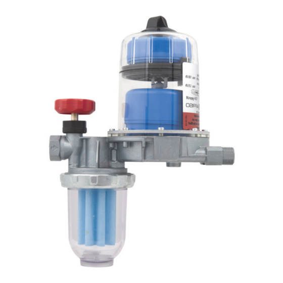
Purgeur d'air automatique avec filtre intégré pour fuel
Table des Matières
Les langues disponibles
Les langues disponibles
Liens rapides
Betriebsanleitung
Automatischer Heizölentlüfter
mit integriertem Filter
Version: 12.2016.0
ID: 900.000.0287
Copyright 2016 AFRISO-EURO-INDEX GmbH. Alle Rechte vorbehalten.
in Verbindung mit einem
PA-Schlauch 4 x 1 mm
FloCo-Top-1K
BRL A Teil 1
Telefon +49 7135-102-0
EN 12514-2
Service +49 7135-102-211
Telefax +49 7135-102-147
DE
Lindenstraße 20
74363 Güglingen
info@afriso.com
www.afriso.com
Table des Matières

Manuels Connexes pour afriso FloCo-Top-1K


Sommaire des Matières pour afriso FloCo-Top-1K
-
Page 54: Purgeur D'air Automatique Avec Filtre Intégré Pour Fuel
Notice technique Purgeur d'air automatique avec filtre intégré pour fuel FloCo-Top-1K Copyright 2016 AFRISO-EURO-INDEX GmbH. Tous droits réservés. Lindenstraße 20 74363 Güglingen BRL A partie 1 Telefon +49 7135-102-0 EN 12514-2 Service +49 7135-102-211 Telefax +49 7135-102-147 info@afriso.com En liaison avec Version: 12.2016.0... - Page 55 La présente notice technique La présente notice technique Cette notice technique contient la description du purgeur d'air automatique avec filtre intégré pour fuel "FloCo-Top-1K" (dénommé ci-après "produit"). Cette notice technique fait partie du produit. • Utilisez le produit seulement après que vous aurez lu et compris intégra- lement la notice technique.
-
Page 56: Consignes De Sécurité Et Classes De Risques
En fonction de la gravité du risque les consignes de sécurité sont réparties dans diffé- rentes classes de risques. AVIS AVIS signale une situation potentiellement dangereuse qui, si elle n'est pas évi- tée, peut entraîner un dommage matériel. FloCo-Top-1K... -
Page 57: Informations Sur La Sécurité
Pendant l'utilisation du produit effectuez toutes les opérations exclusivement dans les conditions spécifiées dans cette notice technique et sur la plaque signalétique, conformément aux données techniques spécifiées et en accord avec tous les règlements, normes et consignes de sécurité en vigueur sur le lieu d'installation. FloCo-Top-1K... - Page 58 Modification du produit En travaillant sur le produit et avec celui-ci, effectuez exclusivement les opé- rations décrites dans cette notice technique. N'effectuez pas de modifica- tions non décrites dans cette notice technique. FloCo-Top-1K...
-
Page 59: Transport Et Stockage
Utilisez l'emballage d'origine pour le transport. • Stockez le produit dans un lieu sec et propre. • Assurez-vous que le produit est à l'abri des chocs pendant le transport et le stockage. La non-observation de ces instructions peut causer des dommages maté- riels. FloCo-Top-1K... - Page 60 La chambre supérieure empêche l'écou- lement du mousse de fuel par l'orifice de purge (par exemple pendant la mise en service / le changement de filtre) et indique un éventuel dysfonc- tionnement de la soupape de purge. FloCo-Top-1K...
-
Page 61: Description Du Produit
A. Q Réservoir Gicleur B. Q Retour C. Q Aller D. Q Dicleur Agréments, certificats, déclarations Le produit est testé par le TÜV (rapport no° S 133 2013 E2). FloCo-Top-1K... -
Page 62: Caractéristiques Techniques
50-70 µm matière plastique Siku (article 69960), autres articles : voir l'étiquette sur l'emballage Plage de température Ambiante Max. +60 °C Fluide Max. +60 °C Matériaux Compartiment purgeur Plastique transparent Bol du filtre Plastique transparent Boîtier Zinc moulé sous pression FloCo-Top-1K... -
Page 63: Montage
50 mbar est considérée pour la pollution résultante. La perte de pression due au frottement dans la conduite est basée sur la densité maximum de fuel EL de 860 kg/m et la viscosité cinématique de 6 /s selon DIN 51603. FloCo-Top-1K... - Page 64 Longueur max. de la conduite d'aspiration en cas de niveau du réservoir inférieur 1. Quand la conduite d'aspi- ration est posée comme conduite d'aspiration à sécurité intrinsèque conformément aux règles techniques tous les cla- pets anti-retour doivent être retirés en amont du produit. FloCo-Top-1K...
- Page 65 > 100 > 100 15 kg/h Ø 6 mm (18 l/h) Ø 8 mm Ø 10 mm > 100 > 100 > 100 20 kg/h Ø 6 mm (24 l/h) Ø 8 mm Ø 10 mm > 100 > 100 FloCo-Top-1K...
- Page 66 (effet siphon). 1 = Valve anti-siphon à piston "KAV" 2 = Valve anti-siphon à membrane "MAV" = Hauteur d’aspiration effective "KAV" =Hauteur d’aspiration effective "MAV" FloCo-Top-1K...
- Page 67 (6 l/h) 7,5 kg/h Ø 4 mm (9 l/h) Ø 6 mm 10 kg/h Ø 4 mm (12 l/h) Ø 6 mm 15 kg/h Ø 6 mm (18 l/h) 20 kg/h Ø 6 mm (24 l/h) Ø 8 mm FloCo-Top-1K...
-
Page 68: Montage Du Produit
N'utilisez pas du ruban téflon ou du chanvre. • Utilisez un raccord tube selon DIN 3852 avec filetage cylindrique (filetage G) et assurez l'étanchéité avec un garniture plate ou une colle adaptée. La non-observation de ces instructions peut causer des dommages maté- riels. FloCo-Top-1K... -
Page 69: Essai De Pression
Lors de l'essai de pression de la conduite d'aspiration, ne raccordez pas la pression au produit, car le clapet anti-retour incorporé à l'appareil ne permet pas d'appliquer la pression à la conduite d'aspiration. 1. Le produit ne doit pas être inclus à l'essai de pression. FloCo-Top-1K... -
Page 70: Perte De Pression
C. Feutre D. Tamis en acier Débit Q [l/h] 5.5.2 En mode aspiration avec filtre encrassé, 50 % 1. Elément filtrant Siku 35 µm 2. Elément filtrant Siku 70 µm 3. Feutre 4. Tamis en acier Débit Q [l/h] FloCo-Top-1K... - Page 71 Montage Liaison du tuyau de purge A. Raccord tuyau avec anneau torique B. Tuyau de purge 1. Démontez le couvercle à l'aide d'un tournevis. FloCo-Top-1K...
- Page 72 à la conduite d'aspiration ou au raccord de retour de l'unité de vidange pour empêcher une obtu- ration possible de la conduite. Le raccord au raccord de retour de l'unité de vidange peut être effectué à l'aide de pièce de raccordement tuyau fourni. FloCo-Top-1K...
-
Page 73: Mode Pression
0,7 bar. Prévoyez un bac de rétention sous les flexibles du brûleur et le purgeur d'air pour fuel afin de permettre de détecter une fuite de fuel et assurer l'arrêt du brûleur. FloCo-Top-1K... -
Page 74: Accumulation D'air Dans Le Bol De Filtre
Le produit est approprié à l'utilisation dans des zones à risque d'inondation et étanche à l'eau jusqu'à une colonne d'eau de 10 m (1 bar pression). AVIS PRODUIT NON OPÉRATIONNEL • Remplacez le produit après une inondation. La non-observation de ces instructions peut causer des dommages maté- riels. FloCo-Top-1K... - Page 75 Si nécessaire Nettoyez les parties plastiques avec mousse de savon. N' utilisez pas de produits contenant de solvants. Annuellement ou si Replacez l'élément filtrant nécessaire Tous les 5 ans Remplacez les flexibles de brûleur Après 20 ans Remplacez le produit FloCo-Top-1K...
- Page 76 Raccords non étanches Assurez-vous de l'étan- dans le tube l'aspiration chéité des raccords Première mise en ser- Utilisez une pompe vice sans pompe d'aspi- d'aspiration ration Conduite d'aspiration Veillez la vitesse d'écou- surdimensionnée lement 0,2 - 0,5 m/s (DIN 4755-2 ) FloCo-Top-1K...
-
Page 77: Suppression Des Dérangements
(minimum 0,6 bar) La pompe du brûleur ne Effectuez un essai crée pas une dépres- d'aspiration de la sion suffisante pompe. La pompe doit générer une dépression de -0,4 bar au moins Autre dérangement Veuillez contacter l'AFRISO Service Hot- line FloCo-Top-1K... -
Page 78: Mise Hors Service Et Élimination
2. Éliminez le produit. Retour Avant de retourner le produit, il faut que vous preniez contact avec nous. Garantie Les informations sur la garantie figurent dans nos "Conditions générales de vente" sur le site www.afriso.com ou dans votre contrat de vente. FloCo-Top-1K... -
Page 79: Dommages Dus À Des Pièces Inadaptées
La non-observation de ces instructions peut causer des dommages maté- riels. Produit Désignation de l'article Référence Figure Purgeur d'air automatique 69960 avec filtre intégré pour fuel "FloCo-Top-1K" Pièces détachées et accessoires Désignation de l'article Référence Figure Bol de filtre court (stan- 20254 dard) Bol de filtre court... -
Page 80: Pièces Détachées Et Accessoires
Tube Ø 8 mm 20508 Tube Ø 10 mm 20510 Tube Ø 12 mm 20512 Valve anti-siphon à piston 20240 "KAV" Valve anti-siphon à 20139 membrane "MAV" Tuyau de purge, 20696 PVC, Ø 4 x 1 mm, 20 m rou- leau FloCo-Top-1K...